EP1007882B1 - Ummantelung für brennerlanze - Google Patents
Ummantelung für brennerlanze Download PDFInfo
- Publication number
- EP1007882B1 EP1007882B1 EP98945147A EP98945147A EP1007882B1 EP 1007882 B1 EP1007882 B1 EP 1007882B1 EP 98945147 A EP98945147 A EP 98945147A EP 98945147 A EP98945147 A EP 98945147A EP 1007882 B1 EP1007882 B1 EP 1007882B1
- Authority
- EP
- European Patent Office
- Prior art keywords
- rings
- segments
- external pipe
- lance according
- burning lance
- Prior art date
- Legal status (The legal status is an assumption and is not a legal conclusion. Google has not performed a legal analysis and makes no representation as to the accuracy of the status listed.)
- Expired - Lifetime
Links
Images

Classifications
-
- F—MECHANICAL ENGINEERING; LIGHTING; HEATING; WEAPONS; BLASTING
- F27—FURNACES; KILNS; OVENS; RETORTS
- F27D—DETAILS OR ACCESSORIES OF FURNACES, KILNS, OVENS OR RETORTS, IN SO FAR AS THEY ARE OF KINDS OCCURRING IN MORE THAN ONE KIND OF FURNACE
- F27D99/00—Subject matter not provided for in other groups of this subclass
- F27D99/0001—Heating elements or systems
- F27D99/0033—Heating elements or systems using burners
-
- F—MECHANICAL ENGINEERING; LIGHTING; HEATING; WEAPONS; BLASTING
- F23—COMBUSTION APPARATUS; COMBUSTION PROCESSES
- F23D—BURNERS
- F23D14/00—Burners for combustion of a gas, e.g. of a gas stored under pressure as a liquid
- F23D14/46—Details
- F23D14/72—Safety devices, e.g. operative in case of failure of gas supply
- F23D14/76—Protecting flame and burner parts
-
- F—MECHANICAL ENGINEERING; LIGHTING; HEATING; WEAPONS; BLASTING
- F23—COMBUSTION APPARATUS; COMBUSTION PROCESSES
- F23D—BURNERS
- F23D2214/00—Cooling
-
- F—MECHANICAL ENGINEERING; LIGHTING; HEATING; WEAPONS; BLASTING
- F23—COMBUSTION APPARATUS; COMBUSTION PROCESSES
- F23D—BURNERS
- F23D2900/00—Special features of, or arrangements for burners using fluid fuels or solid fuels suspended in a carrier gas
- F23D2900/00018—Means for protecting parts of the burner, e.g. ceramic lining outside of the flame tube
Definitions
- the invention relates to a burner lance, in particular for Rotary tube furnaces made of several concentric tubes for guidance of cooling air, combustion air and fuel, nozzles on flame-side end and a refractory jacket of the outer tube, as for example in DE-Z .: E. Steinbiß "multi-jet burner for special requirements for coal dust combustion "in cement-lime gypsum (35th year) No. 5/1982, pp. 250 to 252.
- a burner with concentric tubes for guiding Cooling air, combustion air and fuel, in which the outside Pipe is surrounded by a refractory coating that attached to the outer tube by anchors is off U.S. Patent 4,614,159.
- DE-C-4 405 382 discloses a burner tube with a refractory casing, in which reinforcements are inserted.
- jacket nozzles for rotary kilns
- one at its free End provided with at least one nozzle opening
- It is a tubular hollow body penetrating the furnace jacket known according to German utility model 72 43 054, the hollow body with a tubular, ceramic casing to be provided in the form of a cladding tube, wherein between the tubular hollow body and the cladding tube spacer Setting a coaxial distance are arranged.
- Such burner lances in rotary kilns are used for burning of cement clinker and lime or for firing and sintering Dolomite, magnesite, phosphate or pigments, for annealing Diatomaceous earth and for the thermal treatment of other raw materials used.
- Those used in such rotary kilns Burner lances are subject to high thermal and mechanical stress at the flame end of the Burner lance is largest.
- the burner lances protrude freely bearing over a length of up to currently 12 m in the Rotary kiln inside and are one hot and chemical as well exposed to mechanically aggressive atmosphere.
- Burner lance is in the concentric tubes Combustion air as cooling air or additional cooling air guided while using the outer tube on its outside is provided with a fireproof casing, which is usually from one attached to anchors of the outer tube, fireproof ramming compound. Because of the particularly high Stress on the flame side of the burner lance the fireproof sheathing usually for the flame side Conical thickening at the end.
- the invention is therefore based on the problem that Improve burner lances so that a longer one with them Operating period without interrupting furnace operation is achievable.
- the rings or segments with their radial anchor elements assume a temperature that is between that of the outside Tube and the outer surface of the refractory casing lies. This results in lower differences in elongation between the rings or segments and the refractory Sheathing so that the risk of cracking and Flaking is reduced. Furthermore it is possible to Operation after chipping of parts of the casing to continue because the cooled rings or segments have another provide adequate thermal protection.
- the space between the rings or segments and the outer Pipe is used to guide cooling air to the flame side End of the burner lance, the number of openings in the outer tube and the length range on which the openings are arranged depending on the length of the Burner lance and the raw materials processed in the rotary kiln as well as the furnace temperature are to be determined, on the one hand, the Passage of a sufficient amount of cooling air guarantee, on the other hand, however, the losses caused by the To keep cooling air low and the rings or segments on not cool down too much on the inside.
- the Anchor elements preferably made of honeycomb on the rings or segments arranged, radially in the direction of Cladding widening ribs exist.
- the fireproof Sheathing can be introduced into the honeycomb as ramming paste be applied with such a thickness that a sufficient Coverage of the ribs is achieved.
- the high-temperature-resistant cast alloy can preferably be one corresponding to the refractory casing Have coefficients of thermal expansion.
- segments are used instead of complete rings, can these be screwed to the outer tube and in Interlocking area also interlock like a sleeve.
- Anchor rods can be attached to the rings or segments, if necessary in addition to the anchor elements in the form of cast-on Ribs attached, preferably welded.
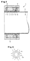
- burner lance one is generally designated by the reference numeral 1 marked burner lance shown, of which only one outer tube 2, but not others, concentric therein arranged pipes and no nozzles on the flame side End shown as these elements are for the invention are immaterial.
- the outer tube 2 is encompassed by rings 4, which on their Have projections 6 inside, which act as spacers serve against the outer surface of the outer tube 2, so that a distance 5 is formed in the form of a free space, into the cooling air through radial bores 8 in the outer tube 2 enter and to the flame end of the burner lance 1 can flow. Due to the arrangement of the spacers 6 there is only point contact between the rings 4 and the outer tube 2, whereby the Heat transfer through conduction between the outer tube 2 and the rings 4 is reduced.
- radial Anchor elements 7 arranged in the form of ribs, which are honeycomb-like are arranged and thus honeycomb openings 10 between them form.
- the ribs 7 widen radially to one widened head 9 so that the honeycomb 10 radially inward Form undercuts for a in Fig. 1 as Rammable casing 3 shown ramming mass Ensure a secure hold.
- the rings 4 preferably consist of a highly heat-resistant cast alloy and have a Coefficient of thermal expansion that the refractory casing comes as close as possible.
- Rings 4 and the radial holes 8 can vary Rings 4 and the radial holes 8 over a more or less large length range of the burner lance 1, starting extend from the flame side end, the number and the Diameter of the radial bores 8 and the width of the free Room 5 should be chosen so that without excessive loss Cooling air ensures the necessary cooling of the rings 4 is.
- rings 4 around these rings can also be divided into segments, which are screwed to the outer tube 2, for example. This division can be advantageous if the The diameter of the outer tube 2 of the burner lance is very large becomes.
Landscapes
- Engineering & Computer Science (AREA)
- Mechanical Engineering (AREA)
- General Engineering & Computer Science (AREA)
- Chemical & Material Sciences (AREA)
- Combustion & Propulsion (AREA)
- Muffle Furnaces And Rotary Kilns (AREA)
- Pre-Mixing And Non-Premixing Gas Burner (AREA)
- Furnace Housings, Linings, Walls, And Ceilings (AREA)
- Blast Furnaces (AREA)
- Furnace Charging Or Discharging (AREA)
Description
- Fig. 1
- einen Querschnitt durch eine erfindungsgemäße Brennerlanze und
- Fig. 2
- einen Längsschnitt durch eine erfindungsgemäße Brennerlanze im Bereich des flammenseitigen Endes.
- Fig. 3
- eine Detailansicht von wabenartigen Rippen zum Halten einer feuerfesten Ummantelung.
Claims (8)
- Brennerlanze, insbesondere für Drehrohröfen, ausmehreren konzentrischen Rohren zur Führung von Kühlluft, Verbrennungsluft und Brennstoff,Düsen am flammenseitigen Ende,einer feuerfesten Ummantelung (3) des äußeren Rohres (2),zwischen der feuerfesten Ummantelung (3) und dem äußeren Rohr (2) angeordneten, das äußere Rohr (2) mit Abstand (5) umgreifenden Ringen (4) oder Segmenten,radialen Ankerelementen (7) an den Ringen (4) oder Segmenten für die feuerfeste Ummantelung (3) undin den Raum (5) zwischen den Ringen (4) oder Segmenten und dem äußeren Rohr (2) mündenden Radialöffnungen (8) im äußeren Rohr (2) zur Kühlluftzufuhr in den Raum (5).
- Brennerlanze nach Anspruch 1, bei der die Ringe (4) oder Segmente auf ihrer dem äußeren Rohr (2) zugekehrten Innenseite regelmäßig verteilte Vorsprünge (6) als Abstandshalter gegenüber der Außenfläche des äußeren Rohrs (2) aufweisen.
- Brennerlanze nach Anspruch 1 oder 2, bei der die Ankerelemente (7) aus wabenförmig auf den Ringen (4) oder Segmenten angeordneten Rippen (7) bestehen.
- Brennerlanze nach Anspruch 3, bei der sich die Rippen (7) radial in Richtung der Ummantelung verbreitern.
- Brennerlanze nach einem der Ansprüche 1 bis 4, bei der benachbarte Ringe (4) im Stoßbereich (13) muffenartig ineinander greifen.
- Brennerlanze nach einem der Ansprüche 1 bis 5, bei der die Ringe (4) oder Segmente aus einer hochtemperaturfesten Gußlegierung bestehen.
- Brennerlanze nach Anspruch 6, bei der die Gußlegierung einen der feuerfesten Ummantelung entsprechenden Temperaturausdehnungskoeffizienten aufweist.
- Brennerlanze nach einem der Ansprüche 1 bis 7, bei der an der Außenoberfläche der Ringe (4) oder Segmente Ankerstäbe (11) befestigt, vorzugsweise angeschweißt sind.
Applications Claiming Priority (3)
| Application Number | Priority Date | Filing Date | Title |
|---|---|---|---|
| DE19737303 | 1997-08-27 | ||
| DE19737303A DE19737303C2 (de) | 1997-08-27 | 1997-08-27 | Brennerlanze, insbesondere für Drehrohröfen |
| PCT/EP1998/004869 WO1999010681A1 (de) | 1997-08-27 | 1998-08-05 | Ummantelung für brennerlanze |
Publications (2)
| Publication Number | Publication Date |
|---|---|
| EP1007882A1 EP1007882A1 (de) | 2000-06-14 |
| EP1007882B1 true EP1007882B1 (de) | 2001-10-24 |
Family
ID=7840312
Family Applications (1)
| Application Number | Title | Priority Date | Filing Date |
|---|---|---|---|
| EP98945147A Expired - Lifetime EP1007882B1 (de) | 1997-08-27 | 1998-08-05 | Ummantelung für brennerlanze |
Country Status (6)
| Country | Link |
|---|---|
| EP (1) | EP1007882B1 (de) |
| AT (1) | ATE207595T1 (de) |
| DE (2) | DE19737303C2 (de) |
| DK (1) | DK1007882T3 (de) |
| ES (1) | ES2166187T3 (de) |
| WO (1) | WO1999010681A1 (de) |
Cited By (1)
| Publication number | Priority date | Publication date | Assignee | Title |
|---|---|---|---|---|
| DE102005053820A1 (de) * | 2005-11-11 | 2007-05-16 | Khd Humboldt Wedag Gmbh | Verfahren und Einrichtung zur Überwachung des Zustandes des Schutzmantels eines Drehofenbrenners |
Families Citing this family (2)
| Publication number | Priority date | Publication date | Assignee | Title |
|---|---|---|---|---|
| DE29911973U1 (de) | 1999-07-09 | 1999-09-30 | Plibrico GmbH, 40210 Düsseldorf | Brennerlanze für eine Zementofenanlage |
| DE202008007506U1 (de) | 2008-06-04 | 2009-10-08 | Refratechnik Holding Gmbh | Feuerfeste Außenverkleidung für eine Brennerlanze |
Family Cites Families (4)
| Publication number | Priority date | Publication date | Assignee | Title |
|---|---|---|---|---|
| DE7243054U (de) * | 1974-05-16 | Krupp F Gmbh | Manteldüse für Drehrohröfen | |
| JPS6086312A (ja) * | 1983-10-19 | 1985-05-15 | Daido Steel Co Ltd | 微粉炭バ−ナ− |
| DK169446B1 (da) * | 1991-04-19 | 1994-10-31 | Smidth & Co As F L | Brænder til roterovn samt fremgangsmåde til dannelse af en brænderflamme med brænderen |
| DE4405382C1 (de) * | 1994-02-19 | 1995-05-24 | Veitsch Radex Ag | Brennerrohr für Brenner in Industrieöfen |
-
1997
- 1997-08-27 DE DE19737303A patent/DE19737303C2/de not_active Expired - Fee Related
-
1998
- 1998-08-05 ES ES98945147T patent/ES2166187T3/es not_active Expired - Lifetime
- 1998-08-05 DK DK98945147T patent/DK1007882T3/da active
- 1998-08-05 DE DE59801890T patent/DE59801890D1/de not_active Expired - Fee Related
- 1998-08-05 WO PCT/EP1998/004869 patent/WO1999010681A1/de not_active Ceased
- 1998-08-05 EP EP98945147A patent/EP1007882B1/de not_active Expired - Lifetime
- 1998-08-05 AT AT98945147T patent/ATE207595T1/de not_active IP Right Cessation
Cited By (1)
| Publication number | Priority date | Publication date | Assignee | Title |
|---|---|---|---|---|
| DE102005053820A1 (de) * | 2005-11-11 | 2007-05-16 | Khd Humboldt Wedag Gmbh | Verfahren und Einrichtung zur Überwachung des Zustandes des Schutzmantels eines Drehofenbrenners |
Also Published As
| Publication number | Publication date |
|---|---|
| EP1007882A1 (de) | 2000-06-14 |
| DE19737303C2 (de) | 1999-09-02 |
| WO1999010681A1 (de) | 1999-03-04 |
| DK1007882T3 (da) | 2002-02-11 |
| DE19737303A1 (de) | 1999-03-04 |
| DE59801890D1 (de) | 2001-11-29 |
| ATE207595T1 (de) | 2001-11-15 |
| ES2166187T3 (es) | 2002-04-01 |
Similar Documents
| Publication | Publication Date | Title |
|---|---|---|
| DE3879273T2 (de) | Ofen mit einem strahlrohrbrenner mit zweistufiger brennstoffzufuhr. | |
| DE69010057T2 (de) | Wärmeofen. | |
| DE102008020204B4 (de) | Brennerhaltevorrichtung mit Kühlsystem für eine Brenneranordnung in einem Flugstromvergaser | |
| EP1466022B1 (de) | Verfahren zur pyrometallurgischen behandlung von metallen, metallschmelzen und/oder schlacken sowie eine injektorvorrichtung | |
| DE1401853A1 (de) | Brenner fuer Tiefoefen od.dgl. | |
| EP3177743B1 (de) | Brenner-lanzen-einheit | |
| WO2009121326A2 (de) | Industrieofen sowie verfahren zum betrieb eines industrieofens | |
| DE2840097A1 (de) | Einrichtung zur rueckgewinnung von waerme aus heissen abgasen | |
| EP1007882B1 (de) | Ummantelung für brennerlanze | |
| EP0534105A2 (de) | Industriebrenner mit rekuperativer Luftvorwärmung, insbesondere zur Beheizung von Ofenräumen von Industrieöfen | |
| DE2215347A1 (de) | Keramischer brenner fuer winderhitzer | |
| DE19905592B4 (de) | Drehrohrofen zur Zementherstellung | |
| DE2258245C3 (de) | Tunnelofen | |
| CH399075A (de) | Brennkammer, insbesondere für magnetogasdynamische Maschinen | |
| DE102006052937A1 (de) | Sammelleitung für Röhrenspaltöfen | |
| DE4430265B4 (de) | Verteilerschurre zum Einbau in einen Ofen | |
| DE7806480U1 (de) | Rotierender waermetauscher | |
| DE1202426B (de) | Rekuperator | |
| DE3321118C2 (de) | Brenner für Schmelzöfen | |
| DE1483052C (de) | Verfahren zur Herstellung von gesinter ten Stoffen m einem Drehrohrofen | |
| DE4409775C2 (de) | Brenner | |
| DE2643412C3 (de) | Drehrohrofen | |
| DE1583444A1 (de) | Elektrischer Ofen,dessen Ofenraum durch ein Rohr begrenzt ist | |
| DE889305C (de) | Strahlrohrofen | |
| DE2924991A1 (de) | Wassergekuehltes ofenwandelement |
Legal Events
| Date | Code | Title | Description |
|---|---|---|---|
| PUAI | Public reference made under article 153(3) epc to a published international application that has entered the european phase |
Free format text: ORIGINAL CODE: 0009012 |
|
| 17P | Request for examination filed |
Effective date: 20000323 |
|
| AK | Designated contracting states |
Kind code of ref document: A1 Designated state(s): AT BE DE DK ES FR GB IT |
|
| GRAG | Despatch of communication of intention to grant |
Free format text: ORIGINAL CODE: EPIDOS AGRA |
|
| GRAG | Despatch of communication of intention to grant |
Free format text: ORIGINAL CODE: EPIDOS AGRA |
|
| GRAH | Despatch of communication of intention to grant a patent |
Free format text: ORIGINAL CODE: EPIDOS IGRA |
|
| 17Q | First examination report despatched |
Effective date: 20010323 |
|
| GRAH | Despatch of communication of intention to grant a patent |
Free format text: ORIGINAL CODE: EPIDOS IGRA |
|
| GRAA | (expected) grant |
Free format text: ORIGINAL CODE: 0009210 |
|
| AK | Designated contracting states |
Kind code of ref document: B1 Designated state(s): AT BE DE DK ES FR GB IT |
|
| REF | Corresponds to: |
Ref document number: 207595 Country of ref document: AT Date of ref document: 20011115 Kind code of ref document: T |
|
| REF | Corresponds to: |
Ref document number: 59801890 Country of ref document: DE Date of ref document: 20011129 |
|
| REG | Reference to a national code |
Ref country code: GB Ref legal event code: IF02 |
|
| GBT | Gb: translation of ep patent filed (gb section 77(6)(a)/1977) |
Effective date: 20020115 |
|
| REG | Reference to a national code |
Ref country code: DK Ref legal event code: T3 |
|
| ET | Fr: translation filed | ||
| REG | Reference to a national code |
Ref country code: ES Ref legal event code: FG2A Ref document number: 2166187 Country of ref document: ES Kind code of ref document: T3 |
|
| PGFP | Annual fee paid to national office [announced via postgrant information from national office to epo] |
Ref country code: DE Payment date: 20020826 Year of fee payment: 5 |
|
| PLBE | No opposition filed within time limit |
Free format text: ORIGINAL CODE: 0009261 |
|
| STAA | Information on the status of an ep patent application or granted ep patent |
Free format text: STATUS: NO OPPOSITION FILED WITHIN TIME LIMIT |
|
| 26N | No opposition filed | ||
| PG25 | Lapsed in a contracting state [announced via postgrant information from national office to epo] |
Ref country code: DE Free format text: LAPSE BECAUSE OF NON-PAYMENT OF DUE FEES Effective date: 20040302 |
|
| PGFP | Annual fee paid to national office [announced via postgrant information from national office to epo] |
Ref country code: ES Payment date: 20040826 Year of fee payment: 7 |
|
| PG25 | Lapsed in a contracting state [announced via postgrant information from national office to epo] |
Ref country code: ES Free format text: LAPSE BECAUSE OF NON-PAYMENT OF DUE FEES Effective date: 20050806 |
|
| REG | Reference to a national code |
Ref country code: ES Ref legal event code: FD2A Effective date: 20050806 |
|
| PGFP | Annual fee paid to national office [announced via postgrant information from national office to epo] |
Ref country code: DK Payment date: 20070828 Year of fee payment: 10 |
|
| PGFP | Annual fee paid to national office [announced via postgrant information from national office to epo] |
Ref country code: AT Payment date: 20070828 Year of fee payment: 10 |
|
| PGFP | Annual fee paid to national office [announced via postgrant information from national office to epo] |
Ref country code: GB Payment date: 20070828 Year of fee payment: 10 |
|
| PGFP | Annual fee paid to national office [announced via postgrant information from national office to epo] |
Ref country code: IT Payment date: 20070828 Year of fee payment: 10 Ref country code: BE Payment date: 20070823 Year of fee payment: 10 |
|
| PGFP | Annual fee paid to national office [announced via postgrant information from national office to epo] |
Ref country code: FR Payment date: 20070821 Year of fee payment: 10 |
|
| REG | Reference to a national code |
Ref country code: DK Ref legal event code: EBP |
|
| GBPC | Gb: european patent ceased through non-payment of renewal fee |
Effective date: 20080805 |
|
| PG25 | Lapsed in a contracting state [announced via postgrant information from national office to epo] |
Ref country code: AT Free format text: LAPSE BECAUSE OF NON-PAYMENT OF DUE FEES Effective date: 20080805 |
|
| REG | Reference to a national code |
Ref country code: FR Ref legal event code: ST Effective date: 20090430 |
|
| PG25 | Lapsed in a contracting state [announced via postgrant information from national office to epo] |
Ref country code: DK Free format text: LAPSE BECAUSE OF NON-PAYMENT OF DUE FEES Effective date: 20080831 Ref country code: BE Free format text: LAPSE BECAUSE OF NON-PAYMENT OF DUE FEES Effective date: 20080831 |
|
| PG25 | Lapsed in a contracting state [announced via postgrant information from national office to epo] |
Ref country code: IT Free format text: LAPSE BECAUSE OF NON-PAYMENT OF DUE FEES Effective date: 20080805 Ref country code: FR Free format text: LAPSE BECAUSE OF NON-PAYMENT OF DUE FEES Effective date: 20080901 |
|
| PG25 | Lapsed in a contracting state [announced via postgrant information from national office to epo] |
Ref country code: GB Free format text: LAPSE BECAUSE OF NON-PAYMENT OF DUE FEES Effective date: 20080805 |