EP1007804B1 - Halteelement zur montage und befestigung von fassadenplatten - Google Patents
Halteelement zur montage und befestigung von fassadenplatten Download PDFInfo
- Publication number
- EP1007804B1 EP1007804B1 EP98938577A EP98938577A EP1007804B1 EP 1007804 B1 EP1007804 B1 EP 1007804B1 EP 98938577 A EP98938577 A EP 98938577A EP 98938577 A EP98938577 A EP 98938577A EP 1007804 B1 EP1007804 B1 EP 1007804B1
- Authority
- EP
- European Patent Office
- Prior art keywords
- shaft
- ball
- connecting element
- ball head
- holding element
- Prior art date
- Legal status (The legal status is an assumption and is not a legal conclusion. Google has not performed a legal analysis and makes no representation as to the accuracy of the status listed.)
- Expired - Lifetime
Links
Images


Classifications
-
- E—FIXED CONSTRUCTIONS
- E06—DOORS, WINDOWS, SHUTTERS, OR ROLLER BLINDS IN GENERAL; LADDERS
- E06B—FIXED OR MOVABLE CLOSURES FOR OPENINGS IN BUILDINGS, VEHICLES, FENCES OR LIKE ENCLOSURES IN GENERAL, e.g. DOORS, WINDOWS, BLINDS, GATES
- E06B3/00—Window sashes, door leaves, or like elements for closing wall or like openings; Layout of fixed or moving closures, e.g. windows in wall or like openings; Features of rigidly-mounted outer frames relating to the mounting of wing frames
- E06B3/54—Fixing of glass panes or like plates
- E06B3/5436—Fixing of glass panes or like plates involving holes or indentations in the pane
- E06B3/5445—Support arms engaging the holes or indentations
-
- E—FIXED CONSTRUCTIONS
- E06—DOORS, WINDOWS, SHUTTERS, OR ROLLER BLINDS IN GENERAL; LADDERS
- E06B—FIXED OR MOVABLE CLOSURES FOR OPENINGS IN BUILDINGS, VEHICLES, FENCES OR LIKE ENCLOSURES IN GENERAL, e.g. DOORS, WINDOWS, BLINDS, GATES
- E06B3/00—Window sashes, door leaves, or like elements for closing wall or like openings; Layout of fixed or moving closures, e.g. windows in wall or like openings; Features of rigidly-mounted outer frames relating to the mounting of wing frames
- E06B3/54—Fixing of glass panes or like plates
- E06B3/5436—Fixing of glass panes or like plates involving holes or indentations in the pane
Definitions
- the invention relates to a holding element for assembling and fastening facade panels, especially glass plates on facades of buildings, with a Connecting element between the facade panel and a support structure, the Connecting element on the outer facing the facade panel Swivel end with a ball head in a counter bearing on the facade panel is mounted and forms a ball joint, and the position of the ball joint in Direction of the longitudinal axis of the connecting element and approximately at right angles to Surface of the facade panel is adjustable.
- Building facades are often clad with facade panels, with the most varied Materials can be used.
- glass plates or plates with photovoltaic elements used. All-glass facades of this type are made from individual glass plates, which abut each other in the edge areas, formed. You need to held by appropriate brackets and connected to the building structure become.
- the building structure forms the static skeleton and the facade panels the aesthetic cladding of the building. So that the aesthetic
- the glass plates should be fully effective when installing alignable in their mutual position and also in the common plane can be aligned with each other.
- facade panels which at the fastening points can be damaged if the plate is subjected to bending loads, this applies in particular to glass plates, corresponding measures are necessary, to reduce these burdens.
- a fastening bolt which is used for fastening of glass plates on a supporting structure.
- the connection between fastening bolts and facade or glass plate is thereby by a ball joint educated.
- the fastening bolt has a ball head at one end on which in a corresponding counter bearing on the facade panel is partially movably clamped.
- the counter bearing on the glass plate is in one Bore inserted in this plate and attached by means of screwed-on flanges attached to the glass plate.
- a threaded pin is formed, over which the fastening bolt is screwed to the support structure.
- This configuration of the fastening bolt reduces the harmful loads on the glass plate in the fastening area due to bending loads. These occur, for example due to wind pressure and suction.
- bending loads These occur, for example due to wind pressure and suction.
- Through the support via the ball head or the ball joint are limited changes in the axis of the glass plate surface possible to the axis of the fastening bolt.
- the right positioning a glass plate within a facade surface and in relation to neighboring Plates are difficult because the adjustment is done with screwed mounting plates must be done with elongated holes.
- the individual attachment points also not individually adjustable, what the orientation partially impossible.
- a device for the assembly and fastening of facade panels, which under Load can be set in all three spatial directions is known from EP 0 712 971.
- This device points in the area of the connection to the supporting structure several components, which are connected to each other via several screw connections are connected.
- This device enables the positioning of the plate holder in all three spatial directions and thus enables the desired orientation of the facade panels in one plane and in relation to each other.
- the multi-part Connection to the supporting structure requires an appropriate installation effort, and the positioning of the plate holder also requires a certain amount of work, to release the various locking devices and after positioning to determine again. It would be desirable to reduce this effort and to enable more rational assembly.
- Connection to the support structure is simplified and the ball head, which on the Facade panel is stored in all three spatial directions in a simple manner pre-positioned and also after installing the facade or glass plate Load can be positioned and at the same time between the outside and the inside thermal insulation is formed on the facade panel.
- the facade or glass plate Load can be positioned and at the same time between the outside and the inside thermal insulation is formed on the facade panel.
- a connecting element which has a spherical head at both ends.
- the outer, first ball head works with a counter bearing on the facade panel and forms a first Ball joint
- the inner, second ball head acts with a counter bearing on the Support structure together and forms a second ball joint.
- the connecting element can be moved tension-free at both ends is and the connection to the support structure requires fewer parts and easier becomes.
- the outer ball head of each holding element can be moved in all three spatial directions, namely within the frame the pre-positioning phase as well as after the facade panel has been installed and fastened. No clamping elements have to be loosened from sliding blocks or the like and then be determined again.
- the arrangement of two ball joints on each holding element prevents the occurrence of undesirable loads and at the same time enables a simplified construction.
- the design of the connecting element between the facade panel and Support structure with two ball joints at both ends has the further advantage that the distance of the outer, first ball joint to the support structure both by changing the length of the shaft as well as by moving the whole Connecting element in the direction of the shaft axis is possible.
- the change the length of the shaft or the distance between the two ball joints is advantageously effected in that the connection between the shaft end and the second, inner ball head through a threaded connection is formed.
- the facility for postponing the whole connecting element in the direction of the longitudinal axis of the shaft can in are advantageously formed in that the second, inner ball joint is arranged in an additional sleeve and this sleeve via a threaded connection form-fitting and adjustable in the jacket part on the support structure is stored.
- the additional positioning means for position shifts arranged approximately parallel to the level of the facade panel.
- these additional positioning means are very simple could be.
- the front End acts on an area of the shaft of the connecting element.
- These set screws are in threaded holes at the front end of the jacket part inserted and there are four screws, two each on lie on a common axis and work together. These set screws are in a manner known per se against unintentional twisting secured.
- the shaft of the connecting element via these additional positioning means can be pivoted about the inner, second ball joint
- a through hole in the casing part the diameter of which is larger is the outside diameter of the shaft.
- this hole is against the front end of the jacket part advantageously expanded in a circumference that releases the desired swivel range of the shaft.
- the counter bearing of the first ball joint on the facade panel is advantageous Way by a housing element and a detachable with the housing element connectable closure part formed. This brings the advantages that the housing element even before installing the facade panel on the facade panel can be pre-assembled. For assembly solutions, for which in the facade panel Holes are provided for the reception of the first, outer counter bearing , these holes can be made by pre-assembling the housing element be protected from damage. Leads especially with glass plates this leads to significant improvements in operations since the connections between the housing element and the facade or glass panels in protected Rooms, e.g. Workshops, executed and their quality, in particular Tightness, can be checked. These connections are therefore no longer necessary when installing the facade, i.e. executed under the disruptive environmental conditions become.
- the connection between the outer, first ball head of the connecting element and the counter bearing on the plate by retracting the first ball head in the housing element and then connecting the closure part with manufactured the housing element.
- the closure part is on the shaft pre-assembled or pre-positioned of the connecting element and it results the advantage that this part is also available in the right place during final assembly is and cannot be lost.
- the housing element is advantageous of the first outer ball joint from at least one inner and one outer part formed. These two parts are by means of releasable connecting means connectable with each other and cover the hole via corresponding shoulders in the facade panel. This arrangement has the advantage that between the outer part, which is exposed to environmental influences, and the inner part Intermediate piece can be used, which consists of insulating material and serves as a thermal break.
- connection to the supporting structure can be fixed and there are no screw connections with elongated holes or clamp connections necessary with sliding blocks.
- parts of the connecting elements namely the Shaft with the two ball heads in the shell parts, which are rigid with the support structure are connected, are pre-assembled.
- first ball joint On the other hand, on the glass plates Parts of the counter bearing for the outer, first ball joint also pre-assembled and be checked. The desired number is on each glass plate provided by counter bearings, normally four with square plates.
- the pre-assembly of the essential elements on the glass plate and on the supporting structure is the assembly of the glass plate and the connection with the support structure very simplified because the counter bearing on the glass plate on the corresponding outer first ball heads of the connecting elements pushed on and then only the closure parts are applied have to.
- the subsequent exact positioning of the plate is via the length adjustment device and the additional positioning means very simple and quickly executable. Then the transitions become known the neighboring plates sealed and connected.
- the invention Structure of the facility simplifies assembly and enables the alignment of the panels during the construction of the facade and also with any later necessary adjustments, i.e. under pressure. It enables also the exchange of individual facade panels within the whole Facade construction.
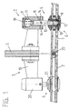
- a section of a facade is shown, which is a supporting structure 5 and on this support structure 5 attached facade panels 2, 3 in the form covered by glass plates.
- facade panels 2, 3 for connecting the glass plates 2, 3 to the supporting structure 5 holding elements 1 according to the invention are provided, each having a fastening flange 19, a jacket part 20, a connecting element 4 and an outer Counter bearing 10 on the glass plates 2, 3 comprises.
- the glass plates 2, 3 are over the connecting elements 4 connected to the support structure 5 and in their mutual Position positioned.
- the abutting edge areas of the glass plates 2, 3 are connected to one another in a known manner via seals 22 and sealed.
- a first, outer ball head 8 is arranged, which Is part of an outer ball joint 6.
- a second, inner ball head 9 is arranged, which Is part of a second, inner ball joint 7.
- a shaft 13 is formed, which around the inner ball joint 7 is pivotable and can be positioned using the positioning means 14 and 15.
- the Positioning means 14 can be displaced in the direction of the axis 16.
- the Shaft 13 via a length adjustment device 18 in the direction of the longitudinal axis 12 displaceable.
- the outer, first ball head 8 in Be positioned in the direction of all three spatial axes.
- first ball joint 6 can move the shaft 13 without transmission are performed by bending forces on the glass plates 2, 3. Are at the same time but also movements of the glass plates 2, 3 around this outer, first ball joint 6 possible, for example as a result of deformations of the plates 2, 3 by Wind pressure or wind suction.
- the right holding element 1 according to FIG. 1 is shown enlarged in FIG. 2. in the The example shown is the mounting flange 19 with the aid of screw connections 23 non-positively and positively connected to the support structure 5.
- the jacket part 20 is fixed to the mounting flange 19 and thus to the support structure 5 connected, the connection between the mounting flange 19 and the jacket part 20 is produced, for example, by a welded connection.
- a through bore 24 is formed in the direction of the longitudinal axis 12, which serves to receive the shaft 13 of the connecting element 4.
- This Bore 24 has a larger diameter than the shaft 13, so that this is movable within the bore 24.
- the shaft 13 has at the outer end a first outer ball head 8 and at the inner end a second, inner ball head 9.
- This Extension 25 has a first bearing surface 26, which has the shape of a lateral surface of a truncated cone.
- the enlarged bore 25 points further an internal thread 29, which with an external thread 30 of a locking ring 27 cooperates.
- the locking ring 27 has a second bearing surface 28 equipped, which also has the shape of a lateral surface of a Has truncated cone.
- the two bearing surfaces 26 and 28 are against each other directed and lie on the outer surface of the ball head 9. So that's the Ball head 9 clamped movably between these two bearing surfaces 26 and 28 and positioned.
- the outer counter bearing 10 for the outer, first Ball head 8 of the ball joint 6 on the facade panels 2, 3 is formed in several parts. It comprises a housing element 21 and a closure part 31, which is detachably connected to the housing element 21.
- the glass plate 3 from two interconnected glass plates, which form an insulating glazing and via known sealing and connecting elements 32 are interconnected.
- the glass plate 3 are for Housing elements 21 passages arranged in the form of a bore 33. Usually are these holes 33 in square glass plates 3 in each four corner areas are provided.
- the housing element 21 can be formed in one piece However, as shown in the example shown, it is expedient several parts. 2 consists of a first, inner part 34 and a second, outer part 35, a connecting element 36 and an intermediate piece 37.
- the two parts 34 and 35 form shoulders, which overlap the bore 33 in the glass plate 3. Between the outer and inner parts 34, 35 of the housing element 21 and the outer and Sealing elements 38, 39 are inserted on the inner surface of the glass plate 3.
- the second, Outer part 35 of housing element 21 is via screw connections 40 connected to the connecting element 36, wherein between the part 35 and the connecting element 36, the intermediate piece 37 is inserted.
- This intermediate piece 37 consists of insulation material with a low thermal conductivity, for example polyamide and acts as a thermal break.
- This intermediate piece 37 also serves as a positioning element for the housing element 21 in the bore 33.
- An external thread is arranged on the connecting element 36, which engages in an internal thread on the inner part 34.
- this threaded connection 41 become the first, inner part 34 and the second, outer part 35 of the housing element 21 clamped together and non-positively with the glass plate 3 connected.
- a bearing surface 42 is formed, which has the shape of a lateral surface Has truncated cone.
- a bearing surface 43 on the closure part 31 is formed, which has the shape of a lateral surface of a truncated cone and against the bearing surface of the housing element 21, or the connecting element 36 is directed.
- These two bearing surfaces 42, 43 lie on the outer surface of the outer, first ball head 8 and this is between them Bearing surfaces 42, 43 movably clamped and positioned.
- the closure part 31 is via the threaded connection 44 with the first, inner part 34 of the housing element 21 releasably connected.
- Threaded bolt 45 is formed with an external thread.
- Threaded bolt 45 there is an active element 47 in the form of a hexagon, via which by means of an auxiliary tool, e.g. a socket wrench, the shaft 13 can be rotated about the axis 12.
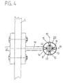
- the shaft 13 On the active axis 16 are on both sides the shaft 13 each have an adjusting screw 14 and an opposite adjusting screw 14 'arranged. On the effective axis 17 arranged at right angles thereto are, as can be seen from Fig. 4, a set screw on both sides of the shaft 13 15 and an adjusting screw 15 'arranged opposite.
- These set screws 14, 14 ', 15 and 15' are used in threaded bores in the casing part 20 and lie with their inner ends on the jacket of the shaft 13. By twisting the set screws in the appropriate direction, the shaft 13 pivot and position around the ball joint 7. If free mobility of the shaft 13 around the ball joint 7 is desired, the set screws 14, 15 are released and the outer, first ball head is then in two spatial directions freely movable.
- the parts 34, 35, 36 and 37 of the housing elements 21 in the bores 33 preassembled.
- the connecting elements 4 are also on the jacket parts 20th pre-assembled and the outer ball head 8 pre-positioned in the desired position.
- the closure part 31, which belongs to the outer counter bearing 10, is attached to the shaft 13 of the connecting element 4 and pre-positioned.
- the closure part 31 has a central through bore 51, which is larger than the diameter of the shaft 31.
- the diameter of this Through hole 51 is, however, smaller than the diameter of the ball head 8 and engages behind this ball head 8.
- FIG. 3 shows another embodiment of the length adjustment device 18 'for the change in the position of the outer, first ball head 8 in the direction of Longitudinal axis 12 shown.
- the shaft 13 of the connecting element 4 is there firmly connected to the second, inner ball head 9.
- the inner counter bearing 11 of the second, inner ball joint 7 with the ball head 9 comprises one Sleeve 52, which is movably connected to the jacket part 20. This is on Outer jacket of the sleeve 52 an external thread 53 arranged, which in a Internal thread 55 of a bore 54 engages in the casing part 20.
- the sleeve 52 is with a central through hole 56 for the shaft 13 of the connecting element 4 equipped.
- An enlarged bore 57 has at the inner end first bearing surface 26 and is against the outer end with an internal thread 58 provided.
- the locking ring 27 is provided with an external thread 59 and screwed into the sleeve 52 by means of the internal thread 58.
- On the inside the locking ring 27 is the second bearing surface 28 for the inner counter bearing 11.
- the first bearing surface 26 and the second bearing surface 28 on the outer surface of the ball head 9 and this is movably clamped between these two bearing surfaces 26, 28.
- the first outer is shifted Ball head 8 along the longitudinal axis 12 in the direction of arrows 48 Rotating the sleeve 52 in the desired direction, which causes this in the Screwed jacket part 20 in or out.
- FIG. 4 is a frontal view of a connecting element 4 according to FIG. 2 or Fig. 3 before installing the facade or glass panels 2, 3.
- the adjusting screws 14 and 14 ' are the adjusting screws 14 and 14 'arranged, which act on the shaft 13 of the connecting element 4.
- the adjusting screws 15 and 15 ' are correspondingly arranged.
- These set screws 14, 14 'and 15, 15' form the additional Positioning means 14, 15. They are in the casing part 20 in transverse bores 49, 50 with Internal threads supported and adjustable.
- the jacket part 20 is over the mounting flange 19 and corresponding screw connections with the Support structure 5 connected. It can be seen that the holding elements according to the invention 1 connected to the support structure 5 in a simple and secure manner can be and the pre-assembly is quick and easy.
Landscapes
- Engineering & Computer Science (AREA)
- Civil Engineering (AREA)
- Structural Engineering (AREA)
- Joining Of Building Structures In Genera (AREA)
- Load-Bearing And Curtain Walls (AREA)
- Finishing Walls (AREA)
Applications Claiming Priority (3)
| Application Number | Priority Date | Filing Date | Title |
|---|---|---|---|
| CH202197 | 1997-08-28 | ||
| CH202197 | 1997-08-28 | ||
| PCT/CH1998/000367 WO1999011884A1 (de) | 1997-08-28 | 1998-08-25 | Halteelement zur montage und befestigung von fassadenplatten |
Publications (2)
| Publication Number | Publication Date |
|---|---|
| EP1007804A1 EP1007804A1 (de) | 2000-06-14 |
| EP1007804B1 true EP1007804B1 (de) | 2003-01-15 |
Family
ID=4224061
Family Applications (1)
| Application Number | Title | Priority Date | Filing Date |
|---|---|---|---|
| EP98938577A Expired - Lifetime EP1007804B1 (de) | 1997-08-28 | 1998-08-25 | Halteelement zur montage und befestigung von fassadenplatten |
Country Status (7)
| Country | Link |
|---|---|
| EP (1) | EP1007804B1 (no) |
| AT (1) | ATE231207T1 (no) |
| AU (1) | AU8725498A (no) |
| DE (1) | DE59806951D1 (no) |
| DK (1) | DK1007804T3 (no) |
| NO (1) | NO320512B1 (no) |
| WO (1) | WO1999011884A1 (no) |
Cited By (2)
| Publication number | Priority date | Publication date | Assignee | Title |
|---|---|---|---|---|
| CN103015592A (zh) * | 2012-12-03 | 2013-04-03 | 沈阳远大铝业工程有限公司 | 多角度连接调整装置 |
| CN106639085A (zh) * | 2016-12-29 | 2017-05-10 | 安徽科蓝特铝业有限公司 | 一种全隐框呼吸式幕墙 |
Families Citing this family (7)
| Publication number | Priority date | Publication date | Assignee | Title |
|---|---|---|---|---|
| DE10114372C2 (de) * | 2001-03-23 | 2003-03-20 | Sws Glasbaubeschlaege Gmbh | Punkthalter |
| WO2003031741A1 (es) * | 2001-10-11 | 2003-04-17 | Giuseppe Barbone | Sistema dinamico de soporte para planchas o laminas |
| CN2549076Y (zh) * | 2002-01-18 | 2003-05-07 | 白宝鲲 | 点支式玻璃幕墙驳接爪 |
| CN2549074Y (zh) * | 2002-01-18 | 2003-05-07 | 白宝鲲 | 点支式玻璃幕墙驳接爪 |
| DE10235493B4 (de) * | 2002-08-02 | 2004-07-22 | Frener & Reifer - Metallbau Gmbh | Befestigungssystem und Befestigungsverfahren |
| CN102926489B (zh) * | 2011-08-11 | 2016-01-20 | 沈阳远大铝业工程有限公司 | 一种抗震式玻璃连接装置 |
| CN103195195A (zh) * | 2013-04-07 | 2013-07-10 | 江苏合发集团有限责任公司 | 一种用于异形框架幕墙连接的万向球铰圆盘机构 |
Family Cites Families (8)
| Publication number | Priority date | Publication date | Assignee | Title |
|---|---|---|---|---|
| DE3843619A1 (de) * | 1988-12-23 | 1990-06-28 | Amanco L & F Ag | Vorrichtung zur verkleidung eines baukoerpers im fassaden- und/oder dachbereich |
| DE3927653A1 (de) | 1989-08-22 | 1991-03-14 | Danz Robert | Halterung fuer eine biegemomentfreie lagerung von wand- oder deckenplatten |
| GB2242248B (en) | 1990-03-21 | 1993-04-14 | Thomas Albert Summers | A structural bolt |
| FR2676768B1 (fr) * | 1991-05-22 | 1995-07-13 | Ponte Jean Francois | Structures architecturales utilisant des parois verrieres de grandes dimensions. |
| FR2703092B1 (fr) * | 1993-03-25 | 1995-06-02 | Vertal Sud Est | Dispositif de fixation d'un vitrage sur une structure porteuse. |
| DE4340511A1 (de) * | 1993-11-27 | 1995-06-08 | Glasbau Seele Gmbh | Gebäudekonstruktion als Fassade oder Dach |
| DE59508168D1 (de) | 1994-11-16 | 2000-05-18 | Vetrotech Saint Gobain Int Ag | Einrichtung zur Montage und Befestigung von Fassadenplatten |
| DE19519527C2 (de) * | 1995-05-27 | 1999-11-18 | Seele Gmbh | Halterung für Platten |
-
1998
- 1998-08-25 DK DK98938577T patent/DK1007804T3/da active
- 1998-08-25 AU AU87254/98A patent/AU8725498A/en not_active Abandoned
- 1998-08-25 EP EP98938577A patent/EP1007804B1/de not_active Expired - Lifetime
- 1998-08-25 DE DE59806951T patent/DE59806951D1/de not_active Expired - Fee Related
- 1998-08-25 AT AT98938577T patent/ATE231207T1/de not_active IP Right Cessation
- 1998-08-25 WO PCT/CH1998/000367 patent/WO1999011884A1/de active IP Right Grant
-
2000
- 2000-02-25 NO NO20000949A patent/NO320512B1/no not_active IP Right Cessation
Cited By (2)
| Publication number | Priority date | Publication date | Assignee | Title |
|---|---|---|---|---|
| CN103015592A (zh) * | 2012-12-03 | 2013-04-03 | 沈阳远大铝业工程有限公司 | 多角度连接调整装置 |
| CN106639085A (zh) * | 2016-12-29 | 2017-05-10 | 安徽科蓝特铝业有限公司 | 一种全隐框呼吸式幕墙 |
Also Published As
| Publication number | Publication date |
|---|---|
| NO320512B1 (no) | 2005-12-12 |
| ATE231207T1 (de) | 2003-02-15 |
| WO1999011884A1 (de) | 1999-03-11 |
| NO20000949L (no) | 2000-02-25 |
| EP1007804A1 (de) | 2000-06-14 |
| DE59806951D1 (de) | 2003-02-20 |
| NO20000949D0 (no) | 2000-02-25 |
| DK1007804T3 (da) | 2003-05-12 |
| AU8725498A (en) | 1999-03-22 |
Similar Documents
| Publication | Publication Date | Title |
|---|---|---|
| EP1853408A1 (de) | Vorrichtung und verfahren zum herstellen einer schraubverbindung zwischen einem ersten bauteil und mindestens einem weiteren bauteil | |
| DE4445724C2 (de) | Befestigungsanordnung von Platten | |
| DE102005044980A1 (de) | Stoßverbinder für Holz-/Aluminiumfassaden | |
| EP1007804B1 (de) | Halteelement zur montage und befestigung von fassadenplatten | |
| EP0333772B1 (de) | Bauelement-system | |
| EP0655542A2 (de) | Gebäudekonstruktion als Fassade oder Dach | |
| DE102007051778A1 (de) | Blindschraubmittel für Hohlkammerprofile | |
| EP4240979A1 (de) | Profilkopplungsanordnung | |
| EP2504511B1 (de) | Bandteil eines scharnierbandes | |
| DE3521783C1 (de) | Abstandsbüchse für die Befestigung eines Beschlagteils an einem mit einem vorgesetzten Profilteil versehenen Hohlprofil | |
| EP3529430B1 (de) | Pfosten für eine pfosten-riegel-konstruktion | |
| DE19831453C2 (de) | Einstellbare Befestigung für Gegenstände, insbesondere Glasplatten auf einer Unterkonstruktion | |
| EP0925419B1 (de) | Klemmbeschlag für die befestigung von glasscheiben | |
| EP1243739A1 (de) | Punkthalter für Platten | |
| DE3603825A1 (de) | Vorrichtung zum verschliessen von gebaeudeoeffnungen | |
| DE10105264C1 (de) | Scharnierband für Türen und Fenster | |
| CH671066A5 (en) | Adjusting mechanism for door and window hinge | |
| DE10231250A1 (de) | System zur Verbindung und/oder Befestigung von Geländerrohren | |
| EP0515845A2 (de) | Verbindungsvorrichtung zur gegenseitigen Fixierung von Riegel und Pfosten von Kunststoff-Fenstern | |
| DE4418082C1 (de) | Mehrteiliges Scharnier | |
| EP1291210B1 (de) | Aufprallträger für Kraftfahrzeug-Tür | |
| DE102007014484A1 (de) | Vorrichtung zum lösbaren Verbinden | |
| DE202007008969U1 (de) | Profilverbinder sowie Profilverbund | |
| EP3960951B1 (de) | Verbinder zum winkligen anschliessen mindestens eines hohlprofils an ein bauwerk sowie anordnung mit mindestens einem solchen verbinder | |
| DE10039278A1 (de) | Justierbare Steckverbindung |
Legal Events
| Date | Code | Title | Description |
|---|---|---|---|
| PUAI | Public reference made under article 153(3) epc to a published international application that has entered the european phase |
Free format text: ORIGINAL CODE: 0009012 |
|
| 17P | Request for examination filed |
Effective date: 20000107 |
|
| AK | Designated contracting states |
Kind code of ref document: A1 Designated state(s): AT BE CH DE DK FI FR IT LI LU NL SE |
|
| TCNL | Nl: translation of patent claims filed | ||
| EL | Fr: translation of claims filed | ||
| GRAG | Despatch of communication of intention to grant |
Free format text: ORIGINAL CODE: EPIDOS AGRA |
|
| RTI1 | Title (correction) |
Free format text: RETAINING ELEMENT FOR MOUNTING AND SECURED FACADE PLATES |
|
| 17Q | First examination report despatched |
Effective date: 20011123 |
|
| GRAG | Despatch of communication of intention to grant |
Free format text: ORIGINAL CODE: EPIDOS AGRA |
|
| GRAH | Despatch of communication of intention to grant a patent |
Free format text: ORIGINAL CODE: EPIDOS IGRA |
|
| GRAH | Despatch of communication of intention to grant a patent |
Free format text: ORIGINAL CODE: EPIDOS IGRA |
|
| GRAH | Despatch of communication of intention to grant a patent |
Free format text: ORIGINAL CODE: EPIDOS IGRA |
|
| GRAA | (expected) grant |
Free format text: ORIGINAL CODE: 0009210 |
|
| AK | Designated contracting states |
Kind code of ref document: B1 Designated state(s): AT BE CH DE DK FI FR IT LI LU NL SE |
|
| REG | Reference to a national code |
Ref country code: CH Ref legal event code: EP |
|
| REG | Reference to a national code |
Ref country code: CH Ref legal event code: NV Representative=s name: WERNER BRUDERER PATENTANWALT |
|
| REF | Corresponds to: |
Ref document number: 59806951 Country of ref document: DE Date of ref document: 20030220 Kind code of ref document: P |
|
| REG | Reference to a national code |
Ref country code: DK Ref legal event code: T3 |
|
| ET | Fr: translation filed | ||
| PLBE | No opposition filed within time limit |
Free format text: ORIGINAL CODE: 0009261 |
|
| STAA | Information on the status of an ep patent application or granted ep patent |
Free format text: STATUS: NO OPPOSITION FILED WITHIN TIME LIMIT |
|
| 26N | No opposition filed |
Effective date: 20031016 |
|
| PGFP | Annual fee paid to national office [announced via postgrant information from national office to epo] |
Ref country code: NL Payment date: 20080826 Year of fee payment: 11 Ref country code: LU Payment date: 20080729 Year of fee payment: 11 Ref country code: DK Payment date: 20080815 Year of fee payment: 11 Ref country code: DE Payment date: 20080829 Year of fee payment: 11 |
|
| PGFP | Annual fee paid to national office [announced via postgrant information from national office to epo] |
Ref country code: FI Payment date: 20080808 Year of fee payment: 11 Ref country code: AT Payment date: 20080715 Year of fee payment: 11 Ref country code: IT Payment date: 20080826 Year of fee payment: 11 Ref country code: FR Payment date: 20080623 Year of fee payment: 11 |
|
| PGFP | Annual fee paid to national office [announced via postgrant information from national office to epo] |
Ref country code: CH Payment date: 20081114 Year of fee payment: 11 |
|
| PGFP | Annual fee paid to national office [announced via postgrant information from national office to epo] |
Ref country code: SE Payment date: 20080814 Year of fee payment: 11 Ref country code: BE Payment date: 20080723 Year of fee payment: 11 |
|
| BERE | Be: lapsed |
Owner name: *VETROTECH SAINT-GOBAIN (INTERNATIONAL) A.G. Effective date: 20090831 |
|
| REG | Reference to a national code |
Ref country code: NL Ref legal event code: V1 Effective date: 20100301 Ref country code: CH Ref legal event code: PL |
|
| REG | Reference to a national code |
Ref country code: DK Ref legal event code: EBP |
|
| PG25 | Lapsed in a contracting state [announced via postgrant information from national office to epo] |
Ref country code: LI Free format text: LAPSE BECAUSE OF NON-PAYMENT OF DUE FEES Effective date: 20090831 Ref country code: FI Free format text: LAPSE BECAUSE OF NON-PAYMENT OF DUE FEES Effective date: 20090825 Ref country code: CH Free format text: LAPSE BECAUSE OF NON-PAYMENT OF DUE FEES Effective date: 20090831 |
|
| REG | Reference to a national code |
Ref country code: FR Ref legal event code: ST Effective date: 20100430 |
|
| PG25 | Lapsed in a contracting state [announced via postgrant information from national office to epo] |
Ref country code: BE Free format text: LAPSE BECAUSE OF NON-PAYMENT OF DUE FEES Effective date: 20090831 Ref country code: AT Free format text: LAPSE BECAUSE OF NON-PAYMENT OF DUE FEES Effective date: 20090825 |
|
| PG25 | Lapsed in a contracting state [announced via postgrant information from national office to epo] |
Ref country code: NL Free format text: LAPSE BECAUSE OF NON-PAYMENT OF DUE FEES Effective date: 20100301 Ref country code: FR Free format text: LAPSE BECAUSE OF NON-PAYMENT OF DUE FEES Effective date: 20090831 Ref country code: DK Free format text: LAPSE BECAUSE OF NON-PAYMENT OF DUE FEES Effective date: 20090831 Ref country code: DE Free format text: LAPSE BECAUSE OF NON-PAYMENT OF DUE FEES Effective date: 20100302 |
|
| PG25 | Lapsed in a contracting state [announced via postgrant information from national office to epo] |
Ref country code: IT Free format text: LAPSE BECAUSE OF NON-PAYMENT OF DUE FEES Effective date: 20090825 |
|
| PG25 | Lapsed in a contracting state [announced via postgrant information from national office to epo] |
Ref country code: LU Free format text: LAPSE BECAUSE OF NON-PAYMENT OF DUE FEES Effective date: 20090825 |
|
| PG25 | Lapsed in a contracting state [announced via postgrant information from national office to epo] |
Ref country code: SE Free format text: LAPSE BECAUSE OF NON-PAYMENT OF DUE FEES Effective date: 20090826 |