EP1006299B1 - Dichtungsanordnung für rotierende Wellen - Google Patents
Dichtungsanordnung für rotierende Wellen Download PDFInfo
- Publication number
- EP1006299B1 EP1006299B1 EP99402950A EP99402950A EP1006299B1 EP 1006299 B1 EP1006299 B1 EP 1006299B1 EP 99402950 A EP99402950 A EP 99402950A EP 99402950 A EP99402950 A EP 99402950A EP 1006299 B1 EP1006299 B1 EP 1006299B1
- Authority
- EP
- European Patent Office
- Prior art keywords
- housing
- sealing lip
- interior volume
- lubricant
- frame
- Prior art date
- Legal status (The legal status is an assumption and is not a legal conclusion. Google has not performed a legal analysis and makes no representation as to the accuracy of the status listed.)
- Expired - Lifetime
Links
- 238000007789 sealing Methods 0.000 title claims description 81
- 239000000314 lubricant Substances 0.000 claims description 31
- 229920001971 elastomer Polymers 0.000 claims description 25
- 239000000806 elastomer Substances 0.000 claims description 24
- 239000004810 polytetrafluoroethylene Substances 0.000 claims description 4
- 229920001343 polytetrafluoroethylene Polymers 0.000 claims description 4
- 239000010687 lubricating oil Substances 0.000 claims description 3
- 239000000428 dust Substances 0.000 claims description 2
- 238000002347 injection Methods 0.000 claims 1
- 239000007924 injection Substances 0.000 claims 1
- 239000003921 oil Substances 0.000 description 15
- 239000002184 metal Substances 0.000 description 6
- 230000002787 reinforcement Effects 0.000 description 3
- 239000007788 liquid Substances 0.000 description 2
- OKTJSMMVPCPJKN-UHFFFAOYSA-N Carbon Chemical compound [C] OKTJSMMVPCPJKN-UHFFFAOYSA-N 0.000 description 1
- 230000000694 effects Effects 0.000 description 1
- 239000000945 filler Substances 0.000 description 1
- 239000003365 glass fiber Substances 0.000 description 1
- 229910002804 graphite Inorganic materials 0.000 description 1
- 239000010439 graphite Substances 0.000 description 1
- 230000005484 gravity Effects 0.000 description 1
- 230000001050 lubricating effect Effects 0.000 description 1
- 238000005461 lubrication Methods 0.000 description 1
- 239000000463 material Substances 0.000 description 1
- 239000011800 void material Substances 0.000 description 1
Images
Classifications
-
- F—MECHANICAL ENGINEERING; LIGHTING; HEATING; WEAPONS; BLASTING
- F16—ENGINEERING ELEMENTS AND UNITS; GENERAL MEASURES FOR PRODUCING AND MAINTAINING EFFECTIVE FUNCTIONING OF MACHINES OR INSTALLATIONS; THERMAL INSULATION IN GENERAL
- F16J—PISTONS; CYLINDERS; SEALINGS
- F16J15/00—Sealings
- F16J15/002—Sealings comprising at least two sealings in succession
- F16J15/006—Sealings comprising at least two sealings in succession with division of the pressure
-
- F—MECHANICAL ENGINEERING; LIGHTING; HEATING; WEAPONS; BLASTING
- F16—ENGINEERING ELEMENTS AND UNITS; GENERAL MEASURES FOR PRODUCING AND MAINTAINING EFFECTIVE FUNCTIONING OF MACHINES OR INSTALLATIONS; THERMAL INSULATION IN GENERAL
- F16J—PISTONS; CYLINDERS; SEALINGS
- F16J15/00—Sealings
- F16J15/16—Sealings between relatively-moving surfaces
- F16J15/32—Sealings between relatively-moving surfaces with elastic sealings, e.g. O-rings
- F16J15/3204—Sealings between relatively-moving surfaces with elastic sealings, e.g. O-rings with at least one lip
- F16J15/3232—Sealings between relatively-moving surfaces with elastic sealings, e.g. O-rings with at least one lip having two or more lips
-
- F—MECHANICAL ENGINEERING; LIGHTING; HEATING; WEAPONS; BLASTING
- F16—ENGINEERING ELEMENTS AND UNITS; GENERAL MEASURES FOR PRODUCING AND MAINTAINING EFFECTIVE FUNCTIONING OF MACHINES OR INSTALLATIONS; THERMAL INSULATION IN GENERAL
- F16J—PISTONS; CYLINDERS; SEALINGS
- F16J15/00—Sealings
- F16J15/16—Sealings between relatively-moving surfaces
- F16J15/32—Sealings between relatively-moving surfaces with elastic sealings, e.g. O-rings
- F16J15/3248—Sealings between relatively-moving surfaces with elastic sealings, e.g. O-rings provided with casings or supports
- F16J15/3252—Sealings between relatively-moving surfaces with elastic sealings, e.g. O-rings provided with casings or supports with rigid casings or supports
Definitions
- the present invention relates to seals seal for rotating shafts, and to devices having such seals.
- the invention relates to a seal intended to be interposed between, of a hand, a crankcase having an interior volume filled with lubricant liquid under certain pressure, and other hand, a shaft emerging from said casing and turning around a longitudinal axis with a certain speed of rotation, this seal comprising a first lip annular sealing which is intended to be secured with the housing and to be in sliding rotary contact with the shaft, the first sealing lip being adapted for withstand a first lower lubricant limit pressure at 1 bar, and to allow rotation speeds shaft speeds greater than 5000 rpm (revolutions per minute).
- EP-A-0 189 723 describes an example of a such a seal, which is perfectly suitable when the lubricant contained in the crankcase is under low pressure.
- this seal which is no longer suitable when this lubricant is at a relatively high pressure, for example greater than 5 bar and generally from 10 to 20 bars, which is particularly the case when the seal fitted to a lubrication bearing under pressure, especially a converter converter bearing automatic gearbox for motor vehicle.
- document GB-A-1 202 061 describes a seal intended to be interposed between, of a hand, a crankcase having an interior volume filled with lubricant liquid under certain pressure, and other hand, a shaft emerging from said casing and turning around a longitudinal axis with a certain speed of rotation, this seal comprising a first lip annular sealing which is intended to be secured with the housing and to be in sliding rotary contact with the shaft, the first sealing lip being adapted for withstand a first lower lubricant limit pressure at 1 bar, and to allow rotation speeds shaft over 5000 rpm, this joint comprising further a second annular sealing lip which is also intended to be secured to the housing and to be in sliding contact with the shaft, the second sealing lip being adapted to allow shaft rotation speeds greater than 5000 rpm and to resist a second limit pressure, higher at 5 bars, prevailing in the interior volume of the casing, this second sealing lip being intended to be interposed between the interior volume of the housing and the first sealing lip, the second sealing lip delimiting with the first sealing lip
- the object of the present invention is in particular to propose a new solution to the above technical problems, which is at least as satisfactory, or even better than that of GB-A-1 202 061.
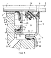
- Figure 1 shows part of a housing 1 at level of a landing 2 crossed by a shaft 3 rotating around a longitudinal axis X.
- Housing 1 which can for example belong to a hydraulic torque converter for gearbox automatic vehicle, includes interior volume 4 filled with pressurized oil.
- the pressure of the oil contained in the interior volume 4 is in all cases greater than 5 bars and generally between 10 and 20 bars, while the speed of rotation of the shaft 3 around the X axis can reach values higher than 5000 rpm, commonly up to 8000 rpm.
- each bearing 2 is provided with a seal 5 which firstly comprises an inner sealing lip 6, symmetrical in shape around the X axis.
- lip 6 is carried by a rigid metal frame 7, also symmetrical in revolution around the X axis.
- the frame 7 has a wall 8 which extends radially outward from an inner edge 8a neighbor of the shaft 3 to an axial fold 9.
- This fold 9 extends towards the inside of the casing 1, and it is itself extended 180 ° outwards from housing 1 by a wall axial 10 in which axial slots 11 are hollowed out or holes, the usefulness of which will be seen later.
- the face of the radial wall 8 which faces the inside of the casing 1 and the face of the axial fold 9 which is oriented radially inward are covered by a layer of elastomer 12 which is adhered to the reinforcement 7.
- the axial fold 9 is force fitted on an axial annular wall 13 which belongs to the casing 1 and which has a cylindrical shape of revolution around of the X axis.
- This annular wall 13 is in sealed contact, radially and axially, with the elastomer layer 12.
- the inner sealing lip 6 advantageously has an L-shaped section, with a radial branch 6a which is adhered to the layer elastomer 12 and an axial branch 6b which extends towards the inside of the casing 1 and which is in rotary contact sliding with the shaft 3 to close the interior volume 4 filled with pressurized oil.
- the inner sealing lip 6 is made in a suitable material to withstand both the pressure of the oil contained in the interior volume 4, and at the shaft rotation speed 3.
- the inner sealing lip 6 is preferably made of PTFE, advantageously loaded with glass fibers and lubricating fillers such as graphite or MoS 2 , to simultaneously limit the wear of the lip 6 and the tree 3.
- the seal 5 further comprises a lip outer sealing ring 14, which has a form of revolution around the X axis and which is in contact rotary sliding with the shaft 3, outside the lip 6.
- This lip 14 preferably has ridges (not shown) on its face in contact with the atmosphere, to locally create an air overpressure.
- the outer sealing lip 14 is formed at the free end of an annular web 15 made of elastomer (rubber) which extends substantially parallel to the X axis from a rigid metal frame 16.
- the free end of the veil 15, which forms the sealing lip 14, is reinforced by a spring helical 17 in the form of a torus.
- the elastomer web 15 forms an annular anti-dust sealing lip 18 at the level of the frame 16.
- the metal frame 16 which has a shape of revolution around the X axis, has a wall 19 which extends radially outward from the web 15 in elastomer up to an axial fold 20 oriented inwards of the casing 1, this axial fold 20 being extended radially outwards by a flange 21 secured to the casing 1 by screws 22 or other fixing means.
- the axial fold 20 of the frame 16 is fitted in a cylindrical cavity 23 of the casing 1, which is centered on the X axis.
- the face radially exterior of the fold 20 is covered with a elastomer layer 24 which is clamped between the fold 20 and the internal wall of the cavity 23.
- the fold 20 is nested by force on the axial wall 10 of the frame 7, without completely covering the slots 11 of said wall 10.
- An oil collecting chamber 25 is delimited axially between, on the one hand, the inner sealing lip 6 and the frame 7, and on the other hand, the lip outer seal 14 and the frame 16.
- the calibrated nozzle 26 is preferably arranged with so that the oil jet coming out of this nozzle does not come not directly strike the sealing lip 14, so as not to not disturb the operation of this sealing lip.
- the sealing lip 14 is permanently lubricated, which guarantees its proper functioning.
- the slots 11 of the frame 7 constitute an oil discharge passage which communicates with a conduit 27 formed in the casing 1 and leading to an oil tank.
- the conduit 27 is oriented downwards, so the oil returns to its tank by gravity.
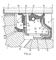
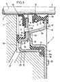
- the second embodiment of the invention which is shown in Figure 2 is similar to the first embodiment. It will therefore not be described in detail, and only the differences from the first embodiment will be discussed below.
- the frame metallic 7 no longer has a fold 9, but only the radial 8 and axial 10 walls, so that the frame 7 has a substantially L-shaped section.
- the axial wall 10 of the frame 7 does not have a slot 11, but only orifices 11a.
- the elastomer layer 12 which is adhered on the inner face of the radial wall 8, extends axially towards the inside of the casing 1 by a lip seal 28 which is applied in sealed contact against the inner wall of a cylindrical cavity 29 of the casing 1, under the effect of the pressure prevailing in the volume interior 4.
- the elastomer web 15 is extended by a layer of elastomer 33 which is adhered to the faces external walls 30 and 31, without covering the collar 32.
- the part of the elastomer layer 33 which covers the wall 31 is clamped radially against the internal wall of the cylindrical cavity 23, so as to form a seal.
Landscapes
- Engineering & Computer Science (AREA)
- General Engineering & Computer Science (AREA)
- Mechanical Engineering (AREA)
- Sealing With Elastic Sealing Lips (AREA)
- Sealing Devices (AREA)
Claims (13)
- Dichtung, die dazu bestimmt ist, zwischen einem Gehäuse (1) einerseits, das einen mit einem flüssigen Schmiermittel gefüllten Innenraum (4) aufweist, das unter einen bestimmten Druck gesetzt wird, und einer aus dem Gehäuse austretenden und sich mit einer bestimmten Drehzahl um eine Längsachse (X) drehenden Welle (3) andererseits eingefügt zu werden, wobei die Dichtung eine erste ringförmige Dichtungslippe (14) umfasst, die dazu bestimmt ist, mit dem Gehäuse verbunden und mit der Welle in Dreh-Gleitkontakt zu sein, wobei die erste Dichtungslippe so ausgeführt ist, dass sie einem ersten Grenzdruck des Schmiermittels von unter 1 bar standhält und Drehzahlen der Welle von über 5.000 U/min ermöglicht, wobei diese Dichtung ferner eine zweite ringförmige Dichtungslippe (6) umfasse die ebenfalls dazu bestimmt ist, mit dem Gehäuse (1) verbunden und mit der Welle (3) In Drehkontakt zu sein, wobei die zweite Dichtungsrippe so ausgeführt ist, dass sie Drehzahlen der Welle von über 5.000 U/min ermöglicht und einem im Innenraum des Gehäuses herrschenden zweiten Grenzdruck von über 5 bar standhält, wobei diese zweite Dichtungslippe dazu bestimmt Ist zwischen dem Innenraum des Gehäuses (4) und der ersten Dichtungslippe (14) eingefügt zu werden, wobei die zweite Dichtungslippe (6) mit der ersten Dichtungslippe (14) eine Kammer zum Sammeln des Schmiermittels (25) begrenzt und die Dichtung ferner Bypass-Mlttel aufweist um eine Verbindung zwischen dem Innenraum des Gehäuses und der Sammelkammer (25) herzustellen,
dadurch gekennzeichnet, dass die Bypass-Mittel eine kalibrierte Düse (26) umfassen, die die zweite Dichtungslippe (6) umgeht, um eine Schmiermittelmenge direkt vom Innenraum (4) des Gehäuses in die Sammelkammer (25) einzuspritzen,
dass die Sammelkammer (25) mit einem Durchlass zum Ableiten von Schmiermittel (11, 11a, 11b) versehen ist,
und dass die kalibrierte Düse (26), die zweite Dichtungslippe (6) und der Durchlass zur Schmiermittelableitung (11, 11a, 11b) so dimensioniert sind, dass in der Sammelkammer (25) ein Schmiermitteldruck herrscht, der höchstens dem ersten Grenzdruck entspricht, wenn das im Innenraum (4) des Gehäuses enthaltene Schmiermittel einen Druck aufweist, der höchstens dem zweiten Grenzdruck entspricht. - Dichtung nach Anspruch 1,
bei der die zweite Dichtungslippe (6) aus PTFE hergestellt ist. - Dichtung nach Anspruch 1 oder Anspruch 2,
bei der die erste Dichtungslippe (14) aus Elastomer hergestellt ist. - Dichtung nach einem der vorhergehenden Ansprüche,
die ferner eine dritte Dichtungslippe (18) als Staubschutz umfasst, die mit dem Gehäuse (1) verbunden und mit der Welle (3) in Dreh-Gleitkontakt ist, wobei die dritte Dichtungslippe in bezug auf die erste Dichtungslippe (14) an der entgegengesetzten Seite der Sammelkammer (25) zum Schutz der ersten Dichtungslippe angeordnet ist. - Dichtung nach einem der vorhergehenden Ansprüche,
bei der die kalibrierte Düse (26) und die zweite Dichtungslippe (6) so dimensioniert sind, dass eine Schmiermittelmenge von 7 bis 100 l/h vom Innenraum (4) des Gehäuses In die Sammelkammer (25) gelangt, wenn im Innenraum ein Druck zwischen 10 und 20 bar herrscht - Dichtung nach einem der vorhergehenden Ansprüche,
bei der der zweite Grenzdruck zwischen 10 und 20 bar liegt. - Dichtung nach einem der vorhergehenden Ansprüche,
bei der die erste und die zweite Dichtungslippe (14, 6) mit einer ersten bzw. zweiten steifen Armierung (16, 7) verbunden sind, die durch Presseinpassen aneinander befestigt sind, wobei wenigstens eine dieser Armierungen wenigstens eine Aussparung (11, 11a, 11b) aufweist, die den Durchlass zur Schmiermittelableitung bildet - Vorrichtung mit:einem Gehäuse (1), das einen Innenraum (4) aufweist, der mit einem flüssigen Schmiermittel gefüllt ist, das unter einen bestimmten Druck gesetzt wird,einer aus dem Gehäuse austretenden und sich mit einer bestimmten Drehzahl um eine Längsachse (X) drehenden Welle (3),und einer zwischen der Welle (3) und dem Gehäuse (1) eingefügten Dichtung (5) nach einem der vorhergehenden Ansprüche, wobei die erste und die zweite Dichtungslippe (14, 6) der Dichtung mit dem Gehäuse verbunden und mit der Welle umlaufend in Dreh-Gleitkontakt ist, wobei die zweite Dichtungslippe (6) axial zwischen dem Innenraum (4) des Gehäuses und der ersten Dichtungslippe (14) angeordnet ist und die kalibrierte Düse (26) zwischen dem Innenraum (4) des Gehäuses und der Sammelkammer (25) eine direkte Verbindung herstellt
- Dichtungsvorrichtung nach Anspruch 8,
bei der die zweite Dichtungslippe (6) einen L-förmigen Querschnitt aufweist, mit einem ersten Schenkel (6a), der mit einer steifen Armierung (7) im Wesentlichen lotrecht zur Längsachse (X) der Welle verlaufend verbunden ist, und einem zweiten Schenkel (6b), der im Wesentlichen parallel zur Längsachse (X) der Welle in Richtung des Innenraums (4) des Gehäuses verläuft. - Dichtungsvorrichtung nach Anspruch 8 oder Anspruch 9,
bei der der Schmiermitteldruck im Innenraum (4) des Gehäuses zwischen 10 und 20 bar liegt, und die zweite Dichtungslippe (6) so ausgeführt ist, dass sie dem Schmiermitteldruck standhält. - Dichtungsvorrichtung nach einem der Ansprüche 8 bis 10,
bei der die erste und die zweite Dichtungslippe (14, 6) mit einer ersten bzw. zweiten steifen Armierung (16, 7) verbunden sind, die durch Presseinpassen aneinander befestigt sind, wobei die zweite Armierung (7) wenigstens eine Aussparung (11) aufweist, die den Durchlass zur Schmiermittelableitung bildet, wobei die erste und die zweite Armierung jeweils eine mit Elastomer beschichtete zylindrische Wand (20, 9) umfasst, die mit dem Gehäuse (1) durch Einstecken zusammenwirkt, um den Innenraum (4) des Gehäuses bzw. die Sammelkammer (25) abzuschließen, und wobei die erste Armierung (16) zudem eine äußere Verlängerung (21) aufweist, die mit dem Gehäuse (1) direkt verbunden ist. - Dichtungsvorrichtung nach einem der Ansprüche 8 bis 10,
bei der die erste und die zweite Dichtungslippe (14, 6) mit einer ersten bzw. zweiten steifen Armierung (16, 7) verbunden sind, die durch Presseinpassen aneinander befestigt sind, wobei die zweite Armierung (7) wenigstens eine Aussparung (11a) aufweist, die den Durchlass für die Schmiermittelableitung bildet, wobei die erste Armierung (16) eine mit Elastomer beschichtete zylindrische Wand (31) umfasst, die mit dem Gehäuse (1) durch Einstecken zusammenwirkt, um die Sammelkammer (25) dicht abzuschließen, wobei die zylindrische Wand durch einen steifen, erweiterten, zylindrischen Kragen (32) verlängert ist, der in direktem Kontakt mit dem Gehäuse (1) ist und der mit dem Gehäuse durch kraftvolles Einstecken zusammenwirkt, wobei die zweite Armierung (7) mit einer zusätzlichen Dichtungslippe (28) verbunden ist, die mit dem Gehäuse zusammenwirkt, um den Innenraum (4) des Gehäuses dicht abzuschlieBen. - Dichtungsvorrichtung nach einem der Ansprüche 8 bis 10,
bei der die erste und die zweite Dichtungslippe (14, 6) mit einer ersten bzw. zweiten steifen Armierung (16, 7) verbunden sind, die unter Einfügen einer Elastomerdichtungsschicht (24) durch Presseinpassen aneinander befestigt sind, wobei die zweite Armierung (7) wenigstens eine Aussparung (11b) aufweist, die den Durchlass zur Schmiermitbelableitung bildet, wobei die erste Armierung (16) mit einer ersten zusätzlichen Dichtungsilppe (24a) aus Elastomer verbunden ist, die mit dem Gehäuse (1) zusammenwirkt, um die Sammelkammer (25) dicht abzuschließen, wobei die zweite Armierung (7) mit einer zweiten zusätzlichen Dichtungslippe (12a) verbunden ist, die mit dem Gehäuse zusammenwirkt, um den Innenraum (4) des Gehäuses dicht abzuschließen, wobei die erste Armierung (16) mit dem Gehäuse (1) direkt verbunden ist und stellenweise auf der zweiten Armierung (7) axial aufliegt.
Applications Claiming Priority (2)
| Application Number | Priority Date | Filing Date | Title |
|---|---|---|---|
| FR9815128 | 1998-12-01 | ||
| FR9815128A FR2786547B1 (fr) | 1998-12-01 | 1998-12-01 | Joint d'etancheite pour arbre tournant, et dispositif comportant un tel joint |
Publications (2)
| Publication Number | Publication Date |
|---|---|
| EP1006299A1 EP1006299A1 (de) | 2000-06-07 |
| EP1006299B1 true EP1006299B1 (de) | 2004-06-23 |
Family
ID=9533414
Family Applications (1)
| Application Number | Title | Priority Date | Filing Date |
|---|---|---|---|
| EP99402950A Expired - Lifetime EP1006299B1 (de) | 1998-12-01 | 1999-11-26 | Dichtungsanordnung für rotierende Wellen |
Country Status (4)
| Country | Link |
|---|---|
| US (1) | US6293558B1 (de) |
| EP (1) | EP1006299B1 (de) |
| DE (1) | DE69918248T2 (de) |
| FR (1) | FR2786547B1 (de) |
Families Citing this family (33)
| Publication number | Priority date | Publication date | Assignee | Title |
|---|---|---|---|---|
| DE20000281U1 (de) | 2000-01-07 | 2000-08-10 | Pumpenfabrik Wangen GmbH, 88239 Wangen | Wellenabdichtung einer rotierenden Maschine durch eine Lippendichtung mit Druckvorlage |
| US6561519B1 (en) * | 2000-11-08 | 2003-05-13 | Freudenberg-Nok General Partnership | Dual seal |
| US6719298B2 (en) * | 2002-01-14 | 2004-04-13 | Skf Usa Inc. | Bonded piston seal for power steering |
| JP3876171B2 (ja) * | 2002-03-08 | 2007-01-31 | 株式会社小松製作所 | オイルシール |
| US20030227140A1 (en) * | 2002-06-11 | 2003-12-11 | Eaton Corporation | Vented high pressure shaft seal |
| US20040146344A1 (en) * | 2003-01-28 | 2004-07-29 | D'amico Anthony T. | Stepped locating diameter for a press fit component |
| US20050087930A1 (en) * | 2003-01-28 | 2005-04-28 | D'amico Anthony T. | Locating bore for press fit and sealing of a press fit component |
| JP4112503B2 (ja) * | 2004-01-09 | 2008-07-02 | ファナック株式会社 | 工作機械用モータの多段オイルシール |
| EP1640644A1 (de) * | 2004-09-27 | 2006-03-29 | Carl Freudenberg KG | Öldichtung |
| AU2005325417A1 (en) * | 2005-01-21 | 2006-07-27 | Nok Corporation | Gasket |
| US20060170298A1 (en) * | 2005-01-28 | 2006-08-03 | Edrington Samuel R | Liquid spray shield for liquid-cooled alternators |
| DE502005005033D1 (de) * | 2005-06-09 | 2008-09-25 | Freudenberg Carl Kg | Dichtung und Anordnung mit in Reihe geschalteten Dichtlippen |
| JP5110250B2 (ja) * | 2006-02-06 | 2012-12-26 | Nok株式会社 | オイルシール |
| FR2897411B1 (fr) | 2006-02-15 | 2008-04-25 | Hutchinson Sa | Dispositif d'etancheite pour carter sous pression et carter dote d'un tel dispositif d'etancheite |
| AT503578B1 (de) * | 2006-04-28 | 2007-11-15 | Andritz Ag Maschf | Dichtanordnung |
| US7959157B2 (en) * | 2006-12-13 | 2011-06-14 | Skf Usa Inc. | Seal with guide member |
| JP5170365B2 (ja) * | 2007-02-16 | 2013-03-27 | Nok株式会社 | 密封装置 |
| JP5310990B2 (ja) * | 2007-05-11 | 2013-10-09 | Nok株式会社 | 密封装置 |
| JP2009103301A (ja) * | 2007-10-02 | 2009-05-14 | Nok Corp | 密封装置 |
| JP5158357B2 (ja) * | 2008-06-09 | 2013-03-06 | Nok株式会社 | 密封装置 |
| US20110206312A1 (en) * | 2008-10-30 | 2011-08-25 | The Timken Company | Endcap for wheel bearing assembly |
| US8544850B2 (en) * | 2009-03-23 | 2013-10-01 | Bal Seal Engineering, Inc. | Seal assemblies for movable and static shafts |
| JP5374395B2 (ja) * | 2010-01-15 | 2013-12-25 | 住友重機械工業株式会社 | オイルシール |
| DE102010031154B4 (de) | 2010-07-09 | 2018-05-17 | Continental Automotive Gmbh | Pumpe zur Förderung eines Fluids, umfassend eine erste und eine zweite in Kontakt stehende Antriebswellendichtung, die einen variabel einstellbaren Drosselkanal zwischen der ersten und zweiten Antriebswellendichtung aufweist |
| JP5757453B2 (ja) * | 2010-10-12 | 2015-07-29 | Nok株式会社 | オイルシール |
| EP2631502A1 (de) * | 2012-02-22 | 2013-08-28 | Aktiebolaget SKF | Lagervorrichtung |
| JP6013230B2 (ja) * | 2013-02-27 | 2016-10-25 | 株式会社小松製作所 | オイルシール |
| WO2015195028A1 (en) * | 2014-06-18 | 2015-12-23 | Trelleborg Forsheda Ab | Sealing arrangement |
| JP6168487B1 (ja) * | 2015-12-04 | 2017-07-26 | Nok株式会社 | 環状のポケットと密封装置とを用いた密封構造 |
| US11104489B2 (en) * | 2018-07-13 | 2021-08-31 | Aktiebolaget Skf | Annular seal having a garter spring for establishing a minimum interior diameter and seal plug including the seal |
| US12410865B2 (en) * | 2020-11-06 | 2025-09-09 | Joel Aaron Shrock | Lubricating seal for reciprocating members |
| JP7563217B2 (ja) * | 2021-02-12 | 2024-10-08 | 東洋製罐株式会社 | ワイピングユニット及び缶ボディメーカー |
| CN117662728A (zh) * | 2022-08-29 | 2024-03-08 | 金风科技股份有限公司 | 密封装置、齿轮箱以及风力发电机组 |
Family Cites Families (11)
| Publication number | Priority date | Publication date | Assignee | Title |
|---|---|---|---|---|
| FR1437899A (fr) * | 1965-06-18 | 1966-05-06 | Angus George Co Ltd | Joint d'étanchéité |
| GB1202061A (en) * | 1967-08-24 | 1970-08-12 | Freudenberg Carl | Packing for reciprocating or rotating engine parts |
| US3682488A (en) * | 1969-09-10 | 1972-08-08 | Nippon Oil Seal Ind Co Ltd | Sealing device |
| FR2408081A1 (fr) * | 1977-11-02 | 1979-06-01 | Paulstra Sa | Perfectionnements aux joints d'etancheite pour arbres rotatifs |
| GB2106196B (en) | 1981-09-16 | 1986-04-09 | Ashlow Ltd | Seals |
| US4428630A (en) * | 1982-07-02 | 1984-01-31 | The Timken Company | Sealed bearing and self-venting seal therefor |
| US4433846A (en) * | 1983-04-20 | 1984-02-28 | Chicago Rawhide Manufacturing Company | Readily removable shaft seal including venting tab |
| JPS60184461U (ja) * | 1984-05-17 | 1985-12-06 | エヌオーケー株式会社 | オイルシ−ル |
| FR2575534B2 (fr) | 1984-12-31 | 1991-11-22 | Hutchinson Sa | Perfectionnements aux joints d'etancheite a levre |
| DE4105746C2 (de) * | 1990-02-26 | 1995-07-13 | Zahnradfabrik Friedrichshafen | Dichtungsanordnung |
| US5398942A (en) * | 1992-09-02 | 1995-03-21 | Dana Corporation | Annular lubricant seal assembly |
-
1998
- 1998-12-01 FR FR9815128A patent/FR2786547B1/fr not_active Expired - Fee Related
-
1999
- 1999-11-26 EP EP99402950A patent/EP1006299B1/de not_active Expired - Lifetime
- 1999-11-26 DE DE69918248T patent/DE69918248T2/de not_active Expired - Fee Related
- 1999-11-29 US US09/450,930 patent/US6293558B1/en not_active Expired - Fee Related
Also Published As
| Publication number | Publication date |
|---|---|
| FR2786547A1 (fr) | 2000-06-02 |
| DE69918248D1 (de) | 2004-07-29 |
| DE69918248T2 (de) | 2005-07-14 |
| EP1006299A1 (de) | 2000-06-07 |
| US6293558B1 (en) | 2001-09-25 |
| FR2786547B1 (fr) | 2001-02-16 |
Similar Documents
| Publication | Publication Date | Title |
|---|---|---|
| EP1006299B1 (de) | Dichtungsanordnung für rotierende Wellen | |
| EP0755488B1 (de) | Hydraulisch betätigtes ausrücklager für kraftfahrzeugkupplung mit membranfeder | |
| EP0631072B1 (de) | Dichtung für Drehwelle | |
| FR2828250A1 (fr) | Installation d'embrayage multiple avec un moyen d'entree pour coupler un amortisseur d'oscillations de torsion | |
| FR2797665A1 (fr) | Reservoir de liquide destine en particulier a un liquide de pression d'une installation hydraulique | |
| FR2587430A1 (fr) | Structure de manchonnage elastique a remplissage de fluide a orifice circonferentiel | |
| FR2799247A1 (fr) | Installation d'embrayage multiple avec une chambre de compension de pression de force centrifuge | |
| FR2799246A1 (fr) | Installation d'embrayage multiple avec au moins un dispostif de palier | |
| FR2651294A1 (fr) | Unite d'etancheite. | |
| FR2512906A1 (fr) | Amortisseur hydraulique telescopique a deux tubes | |
| EP0639726A1 (de) | Einzelstück-Abdichtungsvorrichtung durch eine geschmierte Führung für hydraulische Stossdämpfer | |
| FR2739420A1 (fr) | Pompe a eau | |
| FR2720443A1 (fr) | Joint d'étanchéité à l'huile pour turbine à gaz. | |
| FR2504231A3 (fr) | Joint d'etancheite comprenant deux levres dont l'une est axiale et l'autre radiale, ainsi qu'un labyrinthe | |
| FR2549177A1 (fr) | Systeme pneumatique d'embrayage | |
| FR2604226A1 (fr) | Dispositif pour rendre etanches des paliers d'arbre ou des carters de palier d'arbre. | |
| FR2559231A1 (fr) | Bague d'etancheite radiale pour arbre | |
| FR2774133A1 (fr) | Pompe pour debiter un fluide notamment un liquide hydraulique | |
| EP0332509A1 (de) | Stossdämpfer mit dynamischer Abdichtung | |
| FR2858785A1 (fr) | Reservoir de carburant muni d'un ensemble de valve destine a reduire la permeation de carburant | |
| FR2686065A1 (fr) | Dispositif d'obturation de flacon avec joint d'etancheite. | |
| EP1821007A1 (de) | Abdichtvorrichtung für ein unter Druck stehendes Gehäuse und Gehäuse, das mit einer solchen Abdichtvorrichtung ausgestattet ist | |
| FR2650130A1 (fr) | Joint d'etancheite, dispositif d'etancheite et machine dynamoelectrique ainsi equipes, et ensemble de composants s'y rapportant | |
| EP0976939B1 (de) | Dichtungsvorrichtung für ein Wälzlager | |
| FR2909743A1 (fr) | Joint d'etancheite. |
Legal Events
| Date | Code | Title | Description |
|---|---|---|---|
| PUAI | Public reference made under article 153(3) epc to a published international application that has entered the european phase |
Free format text: ORIGINAL CODE: 0009012 |
|
| AK | Designated contracting states |
Kind code of ref document: A1 Designated state(s): DE GB IT SE |
|
| AX | Request for extension of the european patent |
Free format text: AL;LT;LV;MK;RO;SI |
|
| 17P | Request for examination filed |
Effective date: 20000513 |
|
| AKX | Designation fees paid |
Free format text: DE GB IT SE |
|
| 17Q | First examination report despatched |
Effective date: 20030422 |
|
| GRAP | Despatch of communication of intention to grant a patent |
Free format text: ORIGINAL CODE: EPIDOSNIGR1 |
|
| GRAS | Grant fee paid |
Free format text: ORIGINAL CODE: EPIDOSNIGR3 |
|
| GRAA | (expected) grant |
Free format text: ORIGINAL CODE: 0009210 |
|
| AK | Designated contracting states |
Kind code of ref document: B1 Designated state(s): DE GB IT SE |
|
| REG | Reference to a national code |
Ref country code: GB Ref legal event code: FG4D Free format text: NOT ENGLISH |
|
| REF | Corresponds to: |
Ref document number: 69918248 Country of ref document: DE Date of ref document: 20040729 Kind code of ref document: P |
|
| REG | Reference to a national code |
Ref country code: SE Ref legal event code: TRGR |
|
| GBT | Gb: translation of ep patent filed (gb section 77(6)(a)/1977) |
Effective date: 20040922 |
|
| PLBE | No opposition filed within time limit |
Free format text: ORIGINAL CODE: 0009261 |
|
| STAA | Information on the status of an ep patent application or granted ep patent |
Free format text: STATUS: NO OPPOSITION FILED WITHIN TIME LIMIT |
|
| 26N | No opposition filed |
Effective date: 20050324 |
|
| PGFP | Annual fee paid to national office [announced via postgrant information from national office to epo] |
Ref country code: DE Payment date: 20071108 Year of fee payment: 9 |
|
| PGFP | Annual fee paid to national office [announced via postgrant information from national office to epo] |
Ref country code: IT Payment date: 20071116 Year of fee payment: 9 |
|
| PGFP | Annual fee paid to national office [announced via postgrant information from national office to epo] |
Ref country code: SE Payment date: 20071018 Year of fee payment: 9 |
|
| PGFP | Annual fee paid to national office [announced via postgrant information from national office to epo] |
Ref country code: GB Payment date: 20071114 Year of fee payment: 9 |
|
| EUG | Se: european patent has lapsed | ||
| GBPC | Gb: european patent ceased through non-payment of renewal fee |
Effective date: 20081126 |
|
| PG25 | Lapsed in a contracting state [announced via postgrant information from national office to epo] |
Ref country code: IT Free format text: LAPSE BECAUSE OF NON-PAYMENT OF DUE FEES Effective date: 20081126 |
|
| PG25 | Lapsed in a contracting state [announced via postgrant information from national office to epo] |
Ref country code: DE Free format text: LAPSE BECAUSE OF NON-PAYMENT OF DUE FEES Effective date: 20090603 |
|
| PG25 | Lapsed in a contracting state [announced via postgrant information from national office to epo] |
Ref country code: GB Free format text: LAPSE BECAUSE OF NON-PAYMENT OF DUE FEES Effective date: 20081126 |
|
| PG25 | Lapsed in a contracting state [announced via postgrant information from national office to epo] |
Ref country code: SE Free format text: LAPSE BECAUSE OF NON-PAYMENT OF DUE FEES Effective date: 20081127 |