EP1004534A2 - Fadenabsaugvorrichtung und Fadenabsaug- und Fadenschneidvorrichtung - Google Patents
Fadenabsaugvorrichtung und Fadenabsaug- und Fadenschneidvorrichtung Download PDFInfo
- Publication number
- EP1004534A2 EP1004534A2 EP99123526A EP99123526A EP1004534A2 EP 1004534 A2 EP1004534 A2 EP 1004534A2 EP 99123526 A EP99123526 A EP 99123526A EP 99123526 A EP99123526 A EP 99123526A EP 1004534 A2 EP1004534 A2 EP 1004534A2
- Authority
- EP
- European Patent Office
- Prior art keywords
- yarn
- compressed air
- suction
- guide member
- pipe
- Prior art date
- Legal status (The legal status is an assumption and is not a legal conclusion. Google has not performed a legal analysis and makes no representation as to the accuracy of the status listed.)
- Withdrawn
Links
Images


Classifications
-
- B—PERFORMING OPERATIONS; TRANSPORTING
- B65—CONVEYING; PACKING; STORING; HANDLING THIN OR FILAMENTARY MATERIAL
- B65H—HANDLING THIN OR FILAMENTARY MATERIAL, e.g. SHEETS, WEBS, CABLES
- B65H54/00—Winding, coiling, or depositing filamentary material
- B65H54/70—Other constructional features of yarn-winding machines
- B65H54/71—Arrangements for severing filamentary materials
-
- B—PERFORMING OPERATIONS; TRANSPORTING
- B65—CONVEYING; PACKING; STORING; HANDLING THIN OR FILAMENTARY MATERIAL
- B65H—HANDLING THIN OR FILAMENTARY MATERIAL, e.g. SHEETS, WEBS, CABLES
- B65H35/00—Delivering articles from cutting or line-perforating machines; Article or web delivery apparatus incorporating cutting or line-perforating devices, e.g. adhesive tape dispensers
-
- B—PERFORMING OPERATIONS; TRANSPORTING
- B65—CONVEYING; PACKING; STORING; HANDLING THIN OR FILAMENTARY MATERIAL
- B65H—HANDLING THIN OR FILAMENTARY MATERIAL, e.g. SHEETS, WEBS, CABLES
- B65H54/00—Winding, coiling, or depositing filamentary material
- B65H54/86—Arrangements for taking-up waste material before or after winding or depositing
- B65H54/88—Arrangements for taking-up waste material before or after winding or depositing by means of pneumatic arrangements, e.g. suction guns
-
- B—PERFORMING OPERATIONS; TRANSPORTING
- B65—CONVEYING; PACKING; STORING; HANDLING THIN OR FILAMENTARY MATERIAL
- B65H—HANDLING THIN OR FILAMENTARY MATERIAL, e.g. SHEETS, WEBS, CABLES
- B65H67/00—Replacing or removing cores, receptacles, or completed packages at paying-out, winding, or depositing stations
- B65H67/04—Arrangements for removing completed take-up packages and or replacing by cores, formers, or empty receptacles at winding or depositing stations; Transferring material between adjacent full and empty take-up elements
-
- B—PERFORMING OPERATIONS; TRANSPORTING
- B65—CONVEYING; PACKING; STORING; HANDLING THIN OR FILAMENTARY MATERIAL
- B65H—HANDLING THIN OR FILAMENTARY MATERIAL, e.g. SHEETS, WEBS, CABLES
- B65H2701/00—Handled material; Storage means
- B65H2701/30—Handled filamentary material
- B65H2701/31—Textiles threads or artificial strands of filaments
Definitions
- the present invention relates to yarn sucking and cutting in a yarn winding device for traversing and winding yarn.
- a threading device 1 conventionally comprises a yarn cut device 2, a yarn suction device 3, and a threading arm 10.
- the Threading device 1 is configured so that the yarn cut device 2 cuts a yarn Y being wound around a bobbin B while being traversed on a traverse plane P, so that the yarn suction device 3 subsequently sucks the upstream side of the cut yarn Y, and so that the oscillating threading arm 10 then catches the yarn Y being sucked to pass it to an end of an empty bobbin, as shown in Fig. 11.
- the yarn suction device 3 comprises a yarn suction path 5 including a suction port 4 that is open toward the traverse plane P, and a plate-like cover 6 that is provided to open and close the suction port 4 and that rotationally moves in the direction shown by arrow A.
- the yarn cut device 2 comprises a guide and cut member 9 including a yarn guide surface 7 and a cutting portion 8 downstream of the suction port 4 in a yarn running direction (shown by arrow C) and closer to the inside of the traverse plane P.
- the yarn cut device 2 moves the guide and cut member 9 back and forth between a lower standby position at which it does not intersect the traverse plane P and an upper guide and cut position at which it intersects the traverse plane P.
- the plate-like cover 6 of the yarn suction device 3 is rotationally moved to an open position (shown by a solid line in the drawing) to open the suction port 4, and the guide and cut member 9 of the yarn cut device 2 is elevated to the guide and cut position.
- the traversed yarn Y passes across the guide and cut member 9 of the yarn cut device 2 and then moves in the reverse direction while being traversed.
- the yarn Y is then captured by the yarn guide surface 7 of the yarn cut device 2 and cut by the cutting portion 8, and the upstream side of the cut yarn is sucked into the suction port 4 of the yarn suction device 3.
- the guide and cut member 9 of the yarn cut device 2 is lowered to the standby position, and the yarn Y being sucked is then caught by the oscillating threading arm 10 and passed to an end of an empty bobbin. Subsequently, the plate-like cover 6 of the yarn suction device 3 is rotationally moved to a closed position (shown by an alternate long and two short dashes line in the drawing) to close the suction port 4.
- a known yarn winding device for a draw texturing machine etc. winds a yarn while traversing it and uses a yarn cut device to cut the yarn when the amount of yarn wound reaches a predetermined value, and the device comprises a yarn suction device for sucking and capturing the cut yarn extending upstream of the cut portion.
- the yarn sucked and captured at the suction port of the yarn suction device is passed to an end of an empty bobbin by means of a threading arm of a threading device, and a normal winding operation is then started for the empty bobbin.
- a yarn suction device of this kind has a main suction pipe disposed along the longitudinal direction of the body, and branch pipes branched from the main suction pipe for each spindle in such a way that their suction ports face the traverse plane.
- a blower is provided at one end of the main suction port so that a negative pressure generated in the pipe by the blower generates a suction force at the suction port of the branch pipe to suck the running yarn from the suction port.
- a mere negative pressure generated by the blower may not be able to generate, during fast winding, a sufficient tension to pull the yarn sucked from the suction port of each branch pipe while preventing the yarn from loosening.
- the cut yarn extending downstream of the suction port may fail to be sucked. That is, if the blower is used for suction, a suction force effected at the suction port varies with the distance from the blower, thereby precluding spindles located away from the blower from reliable suction. If the size of the blower is increased to enable the yarn to be reliably sucked and captured, power consumption may increase and the yarn winding device may require a larger and more complicated structure.
- a device that includes compressed air injection nozzle holes in each branch pipe in addition to the blower in order to suck the yarn being wound at a high speed while preventing it from loosening so that compressed air is injected into the branch pipe toward the downstream side to generate a suction force at the suction port.
- a strong suction force is effected near the suction port to reliably suck the yarn
- downstream of the compressed air injection position a waste yarn sucked by means of injected compressed air is reliably ejected into the main suction pipe without hindrance.
- an opening and closing member is provided to close or open the branch pipe relative to the exterior so as to preclude pressure losses when the yarn need not be sucked.
- compressed air injected from the compressed air injection nozzle holes is used to operate the opening and closing member.
- compressed air can be simultaneously supplied to both the compressed air injection nozzle holes and the operation device via the common compressed air supply pipe.
- a known yarn winding device winds a yarn while traversing it and uses a yarn cut device to cut the yarn when the amount of yarn wound reaches a predetermined value, and the device comprises a yarn suction device for sucking and capturing the cut yarn extending upstream of the cut portion.
- the yarn sucked and captured at the suction port of the yarn suction device is passed to an end of an empty bobbin by means of a threading arm of a threading device, and a normal winding operation is then started for the empty bobbin.
- a yarn suction device of this kind has a main suction pipe disposed along the longitudinal direction of the body, and branch pipes branched from the main suction pipe for each spindle in such a way that their suction ports face the traverse plane.
- a blower is provided at one end of the main suction port so that a negative pressure generated in the pipe by the blower generates a suction force at the suction port of the branch pipe to suck the running yarn from the suction port.
- the Unexamined Japanese Patent Application publication (Tokkai-Hei) Number 6-40661 describes a yarn suction device comprising one main suction pipe that has a large number of suction ports over its length and that is connected to a waste yarn capturing/collecting container and a blower for generating a suction flow, wherein each suction port is configured as a branch port and wherein the branch pipe is airtightly installed on the outer circumferential wall of the main suction pipe.
- each branch pipe is configured to be substantially smaller than that of the main suction pipe so as to generate a fast suction flow in the branch pipe to enable the yarn to be reliably sucked and captured, while enabling the large number of suction ports to be simultaneously opened without reducing the suction force.
- the air flow in the main suction pipe is used to generate an air flow in the branch pipe, so the air flows do not smoothly merge together if a large resistance acts on the air flow from the branch pipe merging into the main suction pipe. That is, if, for example, the axis of the branch pipe is orthogonal with the axis of the main suction pipe, the airflow in the main suction pipe may hinder the airflow from the branch pipe from merging into the main suction pipe.
- the Unexamined Japanese Patent Application Publication (Tokkai-Hei) Number 6-40661 describes a configuration in which the axis of the branch pipe is slanted relative to the axis of the main suction pipe so as to allow the yarn to have a motional component moving in the direction of the suction flow in the main suction pipe, thereby avoiding an aerodynamic air checking dynamic pressure at the suction port of the branch pipe to the main suction pipe.
- a device that injects compressed air into the middle of the branch pipe so that the air flow has a motional component moving in a direction toward the main suction to generate, even during fast winding, a sufficient tension to pull the yarn sucked from the suction port of each branch pipe.
- the capacity of a blower connected to the main suction pipe can be reduced to the extent that the waste yarn ejected into the main suction port from the branch pipe can be transferred. If, however, compressed air is injected into the branch pipe to generate a suction force at the suction port in this manner, the air flow from the branch pipe merges into the main suction pipe, collides against the opposed inner circumferential surface of the main suction pipe, and then disperses.
- This dispersion occurs regardless of the direction of the air flow in the main suction pipe, and if, for example, the axis of the branch pipe is orthogonal with the axis of the main suction pipe, an air flow dispersed upstream of the air flow in the main suction pipe interferes with an air flow moving through the main suction pipe from the upstream side to the downstream side to hinder the waste yarn from being transferred through the main suction pipe. If such an air checking effect occurs, the waste yarn transferred from the upstream side are accumulated upstream of the checked position, thereby preventing the waste yarn from being transferred smoothly through the main suction pipe.
- the suction port 4 must be separated from the traverse plane P to prevent the yarn Y being wound from coming in contact with the plate-like cover 6, so the yarn Y cut on the traverse plane P may not be suction into the suction port 4.
- fast winding for example, 1,200 m/min.
- the yarn tension is so high that yarn sucking often fails.
- an object of the present invention is to provide a yarn suction device and a yarn suction and cut device that can allow the yarn to be sucked reliably.
- the suction force effected by compressed air injected from the nozzle holes may be insufficient to normally move the opening and closing member from the closed state to the open state. That is, if, for example, an oscillating opening and closing member is provided at the suction port of the branch pipe, compressed air injected from the nozzle holes generates at the suction port, a suction force moving toward the inside of the branch pipe. The opening and closing member, however, oscillates and opens against the suction force.
- a second object of the present invention is to provide a yarn suction device wherein when a running yarn is to be cut and sucked in a yarn winding device, the opening and closing member can be reliably opened without being hindered by the suction force effected by compressed air injected into the branch pipe.
- the axis of the branch pipe is slanted relative to the axis of the axis of the main suction pipe in order to prevent the waste yarn from being caught near the outlet of the branch pipe due to the checking effect of the air flow in the main suction pipe. That is, in the yarn suction device using the air flow in the main suction pipe to generate an air flow in the branch pipe, the air flow from the branch pipe merging into the main suction pipe does not cause the waste yarn to accumulate inside the main suction pipe.
- this configuration can prevent the branch pipe from being choked with the waste yarn, whereas the waste yarn may accumulate inside the main suction pipe as described above, depending on the relationship between the axes of the branch pipe and main suction pipe, thereby precluding the waste yarn from being normally transferred from the upstream side. That is, in this case, the air in the main suction pipe is hindered from flowing smoothly, thereby precluding yarns from being normally sucked or removed from the other spindles.
- a third object of the present invention is to provide a yarn suction device wherein if compressed air is injected into the middle of the branch pipe to allow the yarn to be more reliably sucked and captured from the suction port, a smooth air flow is constantly maintained inside the main suction pipe to prevent the waste yarn from accumulating inside the main suction pipe, thereby enabling the waste yarn sucked from all branch pipes to be reliably transferred to the downstream end of the main suction pipe for collection.
- a means adopted by the aspect of the present invention to allow a yarn to be reliably sucked is a yarn suction device in which a suction port of a yarn suction path is open so as to face a yarn traverse plane, characterized in that a yarn guide member that advances and withdraws between a standby position at which it does not intersect the traverse plane and a guide position at which it intersects the traverse plane is provided and in that the yarn guide member comprises a yarn guide surface that assumes a position for leading the yarn from the traverse plane to the vicinity of the suction port when the yarn guide member has advanced to the guide position.
- the yarn guide member when the yarn guide member has withdrawn to the standby position, the yarn passes over the traverse plane while being traversed and without coming in contact with the yarn guide member.
- the yarn guide member has advanced to the guide position, the yarn passing while being traversed is captured by the yarn guide surface and the captured yarn is moved in the traversing direction while being guided to the vicinity of the suction port by means of the yarn guide surface.
- a means adopted by the aspect of the present invention to simplify the structure is the above-mentioned yarn suction device, characterized in that the yarn guide member comprises a cover section for closing the suction port once the yarn guide member has withdrawn to the standby position.
- the suction port is covered with the cover section once the yarn guide member has withdrawn to the standby position, whereas the suction port is opened once the yarn guide member has advanced to the guide position.
- a means adopted by the aspect of the present invention to simplify the structure is the above-mentioned yarn suction device, characterized in that a common compressed air path comprising an opening and closing valve is connected to both an operation member for moving the yarn guide member forward using the force of supplied compressed air and a yarn suction path for effecting suction through the suction port using supplied compressed air.
- compressed air is supplied to both the operation member and the yarn suction path to allow the operation member to move the yarn guide member forward while allowing the suction port to enter a sucking state.
- a means adopted by the aspect of the present invention to cut a yarn after it has been reliably sucked is a yarn suction and cut device comprising the above-mentioned yarn suction device and a yarn cut device provided to move a yarn guide member for guiding a captured yarn to a cutting section, back and forth between a standby position at which it does not intersect the traverse plane and a yarn capturing position, characterized in that the device has a control member for controlling activation of the yarn suction device and the yarn cut device to move the yarn guide member of the yarn cut device forward to the yarn capturing position after the yarn guide member of the yarn suction device has been moved forward to a guide position.
- control member activates the yarn guide member of the yarn cut device after activating the yarn guide member of the yarn suction device so that the yarn guide surface of the yarn suction device captures and guides the yarn to the vicinity of the suction port before the yarn cut device cuts it. Consequently, the cut yarn can be reliably sucked into the suction port.
- the aspect of the present invention to achieve the second object is a yarn suction device in which a plurality of branch pipes each having a yarn suction port are branched from a main suction pipe, characterized in that the device comprises compressed air injection nozzle holes for injecting compressed air into the branch pipes so that a flow of air has a motional component that moves toward the main suction pipe, and an opening and closing member for opening and closing the branch pipe relative to the exterior, and in that compressed air is injected from the compressed air injection nozzle holes after the opening operation of the opening and closing member has been started.
- compressed air is injected from the compressed air injection nozzle holes after the opening operation of the opening and closing member has been started, that is, compressed air is not injected from the compressed air injection nozzle holes before the opening operation of the opening and closing member is started.
- the opening operation of the opening and closing member is started before a suction force is generated by the injected compressed air, thereby preventing this operation from being hindered by the suction force effected by the injected compressed air.
- the aspect of the present invention is characterized in that the yarn suction device has an operation member for switching the opening and closing member from a closed state to an open state using supplied compressed air, and in that both the operation member and the compressed air injection nozzle holes are connected to a common compressed air supply pipe comprising an opening and closing valve.
- compressed air is supplied via the common compressed air supply pipe to both the compressed air injection nozzle holes and the operation member for operating the opening and closing member. Consequently, a simple structure can be used to inject compressed air from the nozzle holes while concurrently opening the opening and closing member.
- the operation member has a movement member that moves from a closed position to an open position by means of compressed air supplied via the opening and closing valve and the compressed air supply pipe so that when pressed by the movement member moving to the open position, the opening and closing member is opened, and when the movement member is located at the closed position, the movement member blocks the compressed air supply pipe and the compressed air injection nozzle hole, whereas once the movement member has moved from the closed position to the open position, the compressed air supply pipe comes in communication with the compressed air injection nozzle hole.
- the opening and closing valve is opened to supply compressed air to the operation member via the compressed air supply pipe.
- the compressed air injection nozzle holes are blocked by the movement member located at the closed position and is supplied with no compressed air.
- the movement member of the operation member has moved a predetermined distance in a direction in which the opening and closing member is opened, the movement member presses and opens the opening and closing member of the operation member, and the compressed air supply pipe and the compressed air injection nozzle holes communicate with each other to supply compressed air to the compressed air injection nozzle hole.
- Adjusting the operation member and its peripheral structure enables the setting of how far the movement member of the operation member must be moved to bring the compressed air supply pipe and the compressed air injection nozzle holes in communication with each other. That is, the time from the start of operation of the operation member for the opening and closing member until the start of injection of compressed air from the compressed air injection nozzle holes can be set at a desired value.
- the movement member is a time difference formation member for starting opening of the opening and closing member prior to injection of compressed air from the compressed air injection nozzle holes can be set at a desired value.
- the aspect of the present invention is a yarn suction device that is used for a yarn winding device comprising a plurality of spindles, that includes a plurality of branch pipes branching from a main suction pipe for each spindle, each branch pipe having a suction port and which sucks into a suction pipe arranged upstream of a cutting position a yarn that has been cut by a cutting portion while being wound into a winding package, characterized in that the device has in a direction toward the main suction pipe, compressed air injection nozzle holes for injecting compressed air into the branch pipes between their suction port and terminal, and in that the branch pipe is shaped so that air injected from the compressed air injection nozzle holes merges into the main suction pipe while maintaining the motional component moving toward the downstream side of the air flow in the main suction pipe.
- compressed air is injected from the compressed air injection nozzle holes into the branch pipe between its suction port and terminal to enable a strong suction force to be effected at the suction port.
- compressed air from the branch pipe merges into the main suction pipe toward the downstream side of the air flow in the main suction pipe, the air flow ejected from the branch pipe to the main suction pipe is prevented from blocking the air flow in the main suction pipe, thereby maintaining a smooth air flow in the main suction pipe to enable the waste yarn to be transferred.
- the airflow ejected from the branch pipe serves to amplify the airflow moving downstream through the main suction pipe to improve the yarn transfer capability.
- the aspect of the present invention is characterized in that the inner diameter of the branch gradually increases from the injection positions of the compressed air injection nozzle holes to the main suction pipe.
- the inner diameter of the branch pipe is small at the injection position of the compressed air injection nozzle hole, the air flow velocity is high immediately downstream of the injection position to allow the yarn to be drawn in reliably.
- the inner diameter of the branch pipe gradually increases from this small diameter portion toward the merging portion of the main suction port, airflow generated by injected air can move smoothly through the branch pipe.
- the aspect of the present invention is characterized in that the inner diameter of the branch is smaller than that of the main suction pipe.
- a yarn suction device and a yarn suction and cut device according to the present invention (hereafter referred to as the "present device") is described below based on the first embodiment shown in the drawings.
- the present device can be used for, for example, a draw texturing machine that winds a synthetic filament yarn at a yarn speed of 1,600 m/min.
- a draw texturing machine a synthetic filament yarn released from a yarn supplying package is continuously fed downstream even during the suspension of winding by means of a yarn feeding device.
- Figures 1 to 4 show a first embodiment of the present device.
- Figure 1 is a top view of a threading device comprising the present device.
- Figure 2 is a side view of the threading device.
- Figure 3 is a partial sectional view taken along line III-III in Figure 2, showing a state in which a yarn can be cut.
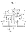
- Figure 4 is a drawing taken along line IV-IV in Figure 2, showing a state in which a yarn cannot be cut.
- a threading device 11 comprises a yarn cut device 12, a yarn suction device 13, and a threading arm 10.
- the threading device 11 is configured so that the yarn cut device 12 cuts a yarn Y being wound around a bobbin B while being traversed on a traverse plane P, so that the yarn suction device 13 subsequently sucks the upstream side of the cut yarn Y, and so that the oscillating threading arm 10 then catches the yarn Y being sucked and passes it to an end Ba of an empty bobbin.
- the yarn suction device 13 comprises a body section 17 including a suction port 14 that is open so as to face the traverse plane P for the yarn Y, a yarn guide member 16 journaled (17a) to the body section 17 so as to lie or oscillate, a spring 18 placed between the body section 17 and the yarn guide member 16 to press the yarn guide member 16 in a direction in which it is brought down, and an operation member 19 placed between the body section 17 and the yarn guide member 16 to press the yarn guide member 16 in a direction in which it is raised.
- the body section 17 comprises a yarn suction path 15 for allowing the suction port 14 that is open in its top surface to communicate with a yarn ejection pipe 20 joined with its lower end, a compressed air path 22 in communication with a compressed air piping 21 including an opening and closing valve 24, and nozzle holes 23 for allowing the compressed air path 22 and the yarn suction path 23 to communicate with each other and injecting compressed air into the yarn suction path 15, wherein the opening and closing valve 24 is opened to inject compressed air to be injected from the nozzle holes 23 in order to generate a suction force at the suction port 14.
- the body section 17 is configured so that compressed air injected from the nozzle holes 23 forms a swirling flow in the yarn suction path 15, the swirling flow serving to maintain a stable air flow velocity on the downstream side of the yarn suction path 15 to allow the yarn Y to be reliably sucked and captured.
- the yarn guide member 16 can lie or oscillate around a direction orthogonal with the axial direction of the bobbin B so as to advance and withdraw between a standby position E at which it does not intersect the traverse plane P (the position shown in Figure 4) and a guide position F at which it intersects the traverse plane P (the position shown in Figure 3).
- the yarn guide member 16 comprises a cover section 16a for closing the suction port 14 when brought down to the standby position E and folded pieces 16b, 16b that connect with the respective longitudinal edges of the cover section 16a, and a sleigh-like yarn guide surface 16c is formed at the lower edge of each folded piece 16b.
- the yarn guide surfaces 16c, 16c of the yarn guide member 16 are formed to assume a position for leading the yarn from the traverse plane P to the vicinity of the suction port 14 after the yarn guide member 16 has advanced to the guide position F (the position shown in Figure 3).
- the yarn guide surface 16c has a section that covers the top of the captured yarn Y while the yarn guide member 16 is at the guide position F, in order to prevent the yarn from jumping up when cut if the yarn is so thick as to effect a high winding tension.
- the yarn guide member 16 has advanced to the guide position F (the position shown in Figure 3), the yarn Y passing while being traversed is captured by the yarn guide surfaces 16c, 16c and the captured yarn is moved in the traversing direction while being guided to the vicinity of the suction port 14 by means of the yarn guide surfaces 16c, 16c.
- the folded piece 16b may be provided at only one longitudinal edge of the cover section 16a.
- the yarn guide surfaces 16c, 16c and the cover section 16a are integrated together to simplify the structure, but the cover section 16a may be omitted.
- the yarn suction device 13 includes an opening and closing valve in the middle of the yarn suction path 15 instead of the cover section 16a so that a common drive source simultaneously or approximately simultaneously operates both the opening and closing valve and the yarn suction device 13 to close the opening and closing valve when the yarn guide member 16 is at the standby position E, while opening the opening and closing valve when the yarn guide member 16 is at the guide position F.
- a piston 25 is placed in an insertion hole 26 drilled in the body section 17 so that the piston 25 can move in the vertical direction, and the compressed air path 22 is in communication with the insertion hole 26.
- the operation member 19 opens the opening and closing valve 24 in the compressed air piping 21, compressed air is guided into the insertion hole 26 through the compressed air path 22. This compressed air elevates the piston 25 to press the yarn guide member 16 up to the guide piston F while accumulating an impact resilience in the compressed spring 18.
- the yarn cut device 12 is provided so that the yarn guide member 29 guiding the captured yarn Y to a cutting portion 28 advances and withdraws between a standby position G (see Figure 2) where it does not intersect the traverse plane P and a yarn capture position H.
- the yarn capture position H corresponds to a height position at which the yarn Y being traversed while being guided by the yarn guide surfaces 16c, 16c of the yarn guide member 16 of the yarn suction device 13 can be captured.
- the yarn guide member 29 is placed so that the yarn Y is cut downstream of the yarn guide member 16 of the yarn suction device 13 in the yarn running direction while part of the yarn Y is being captured (near the suction port 14) by the yarn guide member 16 and so that the direction in which the yarn Y is introduced (the direction shown by arrow K in Figure 1) is opposite to the direction in which the yarn Y is introduced into the yarn guide member 16 of the yarn suction device 13 (the direction shown by arrow M in Figure 1).
- the yarn guide member 29 receives the yarn Y being traversed toward the yarn guide member 29 while being captured by the yarn guide member 16 of the yarn suction device 13.
- the yarn guide member 29 is formed in an oscillation member 30.
- the oscillation member 30 is journaled (32) to a locking bracket 31 so as to oscillate, is operated via an operation lever 33 by an operation member (not shown in the drawings) comprising an air cylinder or a solenoid, and moves the yarn guide member 29 between the standby position G and the yarn capture position H.
- the cutting portion 28 comprising a cutter or a heat ray is provided in the oscillation member 30 to cut the yarn guided by the yarn guide member 29.
- the yarn Y is moved to the right of Figure 1 while being traversed by the traverse guide 34 and is captured by the yarn guide surfaces 16c, 16c of the yarn guide member 16.
- the yarn is further moved rightward, it is traversed around the yarn guide member 16.
- the yarn Y has been captured by the yarn guide member 16
- it is moved leftward while being traversed.
- the yarn is captured and cut by the yarn cut device 12 if the yarn guide member 29 of the yarn cut device 12 has advanced to the yarn capture position H, whereas the yarn continues to be traversed without being cut if the yarn guide member 29 of the yarn cut device 12 has withdrawn to the standby position G.
- the yarn suction and cut device comprising the yarn cut device 12 and the yarn suction device 13 is operated based on a control signal from a control member (not shown in the drawings).
- the control member comprises a circuit configured as follows. After a predetermined amount of yarn has been wound around the bobbin B and when this bobbin B is to be doffed, the circuit moves the yarn guide member 16 of the yarn suction device 13 forward to the guide portion F and then controls activation of the yarn suction device 13 and the yarn cut device 12 so as to move the yarn guide member 29 of the yarn cut device 12 forward to the yarn capture position H.
- the circuit moves the yarn guide member 16 of the yarn suction device 13 and the yarn guide member 29 of the yarn cut device 12 backward to the standby position.
- the yarn Y is continuously fed from the upstream side, so the yarn Y is continuously suction into the suction port 14 to obtain a tension required for the yarn Y.
- the yarn Y connected to the suction port 14 is cut, and a predetermined amount of time later (the time required before the yarn Y extending from the cut position to the suction port 14 has been ejected), the yarn guide member 16 is moved backward (laid) to the standby position E.
- the yarn suction and cut device comprising the yarn cut device 12 and the yarn suction device 13 controls each activation as described above to capture the yarn Y on the yarn guide surfaces 16c, 16c of the yarn suction device 13 and then to guide it to the vicinity of the suction port 14 to cut it. Accordingly, the cut yarn can be reliably sucked into the suction port 14. Once the yarn Y has been sucked and captured, it is continuously and reliably sucked without loosening by means of airflow injected into the compressed air path 22 from the nozzle holes 23 of the yarn suction device 13. After bobbin change, The threading device 11 uses the oscillating threading arm 10 to catch the yarn Y being sucked into the suction port 14 and then to pass it to the empty bobbin end Ba. The yarn Y is wound around the bobbin B to finish threading. Once threading has been completed, normal winding is started with a traverse operation.
- the yarn suction device can be used for a yarn winding device composed of a large number of spindles installed in a line in the longitudinal direction of the body.
- the yarn winding device uses a specified-length measuring device (not shown in the drawings) to detect that the amount of yarn wound around a winding package has reached a predetermined value in order to cut, suck, and hold the running yarn Y before changing the bobbin, and comprises a threading device 1 that threads the end Ba of a new empty bobbin with the yarn.
- a yarn winding device is, for example, a draw texturing machine that winds synthetic filament yarns at a yarn running velocity (a winding velocity) of about 1,600 m/min.
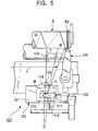
- a threading device 101 comprises a yarn cut device 102, a yarn suction device 103, and a threading arm 104.
- the threading device 101 is configured so that the yarn cut device 102 cuts a yarn Y being wound around a bobbin B while being traversed on a traverse plane P by a traverse guide 125, so that the yarn suction device 103 subsequently sucks the upstream side of the cut yarn Y, and so that the oscillating threading arm 104 then catches the yarn Y being sucked and passes it to the empty bobbin end Ba.
- the yarn winding device comprises a bobbin change device (not shown in the drawings) for replacing an empty bobbin B with a full bobbin B held by a cradle arm.
- the yarn suction device 103 comprises a main suction pipe 111 disposed along the longitudinal direction of the yarn winding device body and a plurality of branch pipes 106 branched from the main suction pipe 111 so as to correspond to each spindle.
- the branch pipe 106 belongs to a suction section of the yarn suction device 103 provided for each spindle, and the suction section comprises a body section 107 including the branch pipe 106 having a suction port 105 that is open so as to face a traverse plane P for the yarn Y, a yarn guide member 108 journaled (107a) to the body section 107 so as to lie or oscillate, an elastic body (a spring) 109 placed between the body section 107 and the yarn guide member 108 to press the yarn guide member 108 in a direction in which it is brought down, and an operation member (an air cylinder) 110 placed between the body section 107 and the yarn guide member 108 to press the yarn guide member 108 in a direction in which it is raised.
- the branch pipe 106
- the plurality of branch pipes 106 are connected to the single main suction pipe 111 in such a way as to be located on the same plane.
- the example in Figure 9 shows that only the most downstream branch pipe 106 is opened, but one or more upstream branch pipes 106 (those on the right of Figure 9) may be simultaneously opened.
- a blower 127 is provided at one end of the main suction pipe 111 to generate in the main suction pipe 111 an air flow moving toward a waste yarn collection container 126.
- a waste yarn ejected from the branch pipe 106 are transferred through the main suction pipe 111 along the air flow in the pipe and the longitudinal direction of the yarn winding device (the lateral direction of Figure 9), and are then collected in the waste yarn collection container 126.
- an opening of a predetermined size is formed at the upstream end of the main suction pipe 111.
- compressed air injection nozzle holes 113 for injecting compressed air into the yarn suction path 112 are formed so that the air flow has a motional component moving toward the main supply pipe 111.
- the plurality of compressed air injection nozzle holes 113 are formed at an equal interval in the circumferential direction so as to inject compressed air in the tangential direction of the yarn suction path 112, which appears to have a circular cross section as seen from the axial direction.
- the yarn suction path 112 includes a tapered section 112a having a diameter gradually decreasing from the suction port 105, a linear reduced diameter section 112b between the tapered section 112a and the compressed air injection positions of the compressed air injection nozzle holes 113, and an increased diameter section 112c having a diameter gradually increasing from the compressed air injection positions to the portion that is joined with the main suction pipe 111.
- the yarn suction path 112 has a diameter gradually increasing from the compressed air injection positions of the compressed air injection nozzle holes 113 to the main suction pipe 111.
- the diameter of the yarn suctions path 112 (the inner diameter of the branch pipe 106) is smaller than the inner diameter of the main suction pipe 111 all over the length of the path.
- the axis of the yarn suction path 112 is configured to tilt so as to form a sharp angle relative to the axis of the main suction pipe 111.
- the air flow in the yarn suction path 112 has a motional component moving toward the downstream side of the main suction pipe 111 (to the left of Figures 7 and 9).
- the lower end of the yarn suction path 112 is bent toward the downstream side of the main suction pipe 111.
- This portion is bent in such a way that, for example, the angle formed between the axis of the yarn suction path 112 and the axis of the main suction pipe 111 is approximately 45 degrees in the junction between the yarn suction path 112 and the main suction pipe 111.
- compressed air injected into the middle of the branch pipe 106 merges into the main suction pipe 111 while maintaining the motional component moving in the same direction as the airflow in the main suction pipe.
- the effect of checking in the main suction pipe 111 the waste yarn transferred from the upstream side is eliminated to reliably prevent the waste yarn from being accumulated or caught.
- the body section 107 has drilled therein an insertion hole 114 in which a piston (a movement member) 115 is placed so as to move vertically between a closed position and an open position.
- the insertion hole 114 has directly connected thereto a compressed air supply pipe 117 connected to an external compressed air source (not shown in the drawings) and comprising an opening and closing valve 116.
- the insertion hole 114 can communicate with the compressed air injection nozzle holes 113 via a recess section 118 formed around the branch pipe 106.
- an operation member 110 opens the opening and closing valve 116 in a compressed air piping 117, compressed air is guided into the insertion hole 114 through the compressed air path 117. This compressed air elevates the piston 115 to the open position to press the yarn guide member 108 up to the guide position F while accumulating an impact resilience in an elastic body 109.
- opening and closing valve 116 When the operation member 110 closes opening and closing valve 116 to stop the supply of compressed air, the impact resilience of the elastic body 109 brings the yarn guide member 108 down to the standby position E and presses the piston 115 to the closed position to eject the air remaining in the insertion hole 114, to the yarn suction path 112 via the recess section 118 and compressed air nozzle holes 113.
- the opening and closing valve 116 is connected to an external control member (not shown in the drawings) and is opened or closed in response to a control signal from the control member with predetermined timings.
- the compressed air supply pipe 117 can communicate with the compressed air injection nozzle holes 113 via the insertion hole 114 and the recess section 118.
- part of the piston blocks the communication between the insertion hole 114 and the recess section 118. Consequently, when compressed air is started to be supplied to the insertion hole 114 (the piston 115 is located at the closed position), the piston 115 blocks the communication to preclude compressed air from being injected from the compressed air injection nozzle holes 113.
- compressed air from the compressed air supply pipe 117 is used as a common drive source for both the opening operation of the yarn guide member 108 and the injection of compressed air from the compressed air injection nozzle holes 113 so that the injection of compressed air from the compressed air injection nozzle holes 113 follows the opening operation of the yarn guide member 108 following the elevation of the piston 115.
- This configuration provides a delay means for slightly delaying the injection of compressed air from the compressed air injection nozzle holes 113 relative to the opening operation of the yarn guide member 108.
- the yarn guide member 108 can lie or oscillate so as to advance and withdraw between a standby position E at which it does not intersect the traverse plane P (the position shown in Figure 8) and a guide position F at which it intersects the traverse plane P (the position shown in Figure 7).
- the yarn guide member 108 can oscillate around the horizontal axis orthogonal with the axial direction of the bobbin B, and the yarn Y being traversed is introduced into the yarn guide member 108 from one side of the traverse direction.
- the yarn guide member 108 comprises a cover section 108a (opening and closing member) for closing the suction port 105 when brought down to the standby position E and folded pieces 108b, 108b that connect with the respective longitudinal edges of the cover section 108a, and a sleigh-like yarn guide surface 108c is formed at the lower edge of each folded piece 108b.
- the yarn guide surfaces 108c, 108c of the yarn guide member 108 are formed to assume a position for leading the yarn from the traverse plane P to the vicinity of the suction port 14 after the yarn guide member 108 has advanced to the guide position F (the position shown in Figure 7).
- the yarn guide surface 108c has a section that covers the top of the captured yarn Y while the yarn guide member 108 is at the guide position F, in order to prevent the yarn Y from jumping up when cut if the yarn Y is so thick as to effect a high winding tension.
- the yarn guide member 108 has advanced to the guide position F (the position shown in Figure 7), the yarn Y passing while being traversed is introduced into the yarn guide member 108 from one side of the traverse direction and captured by the yarn guide surfaces 108c, 108c, and the captured yarn Y is moved in the traversing direction while being guided to the vicinity of the suction port 105 by means of the yarn guide surfaces 108c, 108c.
- the folded piece 108b may be provided at only one longitudinal edge of the cover section 108a.
- the yarn guide surfaces 108c and the cover section 108a are integrated together to simplify the structure, but the cover section 108a may be omitted.
- the yarn suction device 103 includes a slide-type opening and closing valve in the middle of the yarn suction path 105 instead of the cover section 108a so that a common drive source is used to inject compressed air from the compressed air injection nozzle holes 113 after the opening operation of the opening and closing member.
- this configuration closes the opening and closing member when the yarn guide member 108 is at the standby position E, while opening the opening and closing member when the yarn guide member 108 is at the guide position F. In this case, this configuration prevents the opening operation of the opening and closing member from being hindered by the suction force generated in the yarn suction path.
- the yarn cut device 102 is provided so that the yarn guide member 120 guiding the captured yarn Y to a cutting portion 119 advances and withdraws between a standby position G (see Figure 2) where it does not intersect the traverse plane P and a yarn capture position H.
- the yarn capture position H corresponds to a height position at which the yarn Y being captured by the yarn guide member 108 of the yarn suction device 102 and traversed using the yarn guide surfaces 108c as traverse fulcrums can be captured.
- the yarn guide member 120 and the cutting portion 119 are placed so that the yarn Y is cut while being captured (near the suction port 105) by the yarn guide member 108 of yarn suction device 102 and so that the direction in which the yarn Y being traversed is introduced (the direction shown by arrow K in Figure 1) is opposite to the direction in which the yarn Y is introduced into the yarn guide member 108 of the yarn suction device 102 (the direction shown by arrow M in Figure 5).
- the yarn guide member 120 receives the yarn Y being traversed toward the yarn guide member 120 while being captured by the yarn guide member 108 of the yarn suction device 102.
- the yarn guide member 120 is formed in an oscillation member 121.
- the oscillation member 121 is journaled (123) to a locking bracket 122 so as to oscillate, is operated via an operation lever 124 by an operation member (not shown in the drawings) comprising an air cylinder or a solenoid, and moves the yarn guide member 210 between the standby position G and the yarn capture position H.
- the cutting portion 119 comprising a cutter or a heat ray is provided in the oscillation member 121 to cut the yarn guided by the yarn guide member 120.
- the yarn Y is normally wound while being traversed in the lateral direction (the lateral direction of Figure 5) by the traverse guides 102, 105 until the measured length reaches a specified value.
- the opening and closing valve 116 is opened.
- compressed air is supplied to the insertion hole 114 from the compressed air supply pipe 117.
- the piston 115 of the operation member 110 is pressed against the urging force of the elastic body 109 to move the yarn guide member 108 to the guide position F, and a short time later, compressed air is injected into the yarn suction path 112 from the compressed air injection nozzle holes 113.
- the yarn guide member 108 After advancing to the guide position F at which it intersects the traverse plane P, the yarn guide member 108 captures part of the yarn being traversed rightward, and the captured yarn Y is traversed using the position of the yarn guide member 108 as a fulcrum.
- the operation member (not shown in the drawings) is activated to move the yarn guide member 120 forward from the standby position G to the yarn capture position H.
- the cutting portion 119 cuts the yarn Y being traversed leftward using the yarn guide member 108 as a fulcrum.
- the time t1 is set at such an appropriate value that the cover section 108a is opened simultaneously with opening of the opening and closing valve 116, that a short time after the start of the opening operation of the valve, compressed air is injected from the compressed air injection nozzle holes 113, and that the yarn guide member 120 advances to the yarn capture position H after a suction force has been effected at the suction port 105.
- the yarn Y extending downstream of the cut portion is wound around the bobbin B, whereas the yarn Y extending upstream of the cut portion is automatically sucked from the suction port 105.
- a predetermined time t2 has passed since the yarn guide member 120 advanced, the full bobbin B held on the cradle is replaced with the empty bobbin B, and the threading arm 104 is then operated to catch the yarn Y being sucked from the suction port 105 in order to thread the empty bobbin end Ba with the yarn Y.
- the time t2 is set at such an appropriate value that the bobbin change is carried out after the cutting portion 119 has cut the traversed yarn Y after the advance of the yarn guide member 120.
- a yarn feeding device (not shown in the drawings) continuously feeds the yarn from the upstream side even after a yarn cut, the yarn Y is continuously sucked from the suction port 105 to apply a required tension to the yarn until threading has been completed.
- the yarn cut device 102, the suction section of the yarn suction device 103, and the threading arm 104 are activated based on a control signal from a control member (not shown in the drawing). For example, with respect to the withdrawing operation of the yarn guide member 120, it can be moved backward to the standby position G immediately after cutting.
- a cut device (not shown in the drawings) different from the yarn cut device 102 may cut the yarn connecting to the suction port 105, and a predetermined time later (the time required before the yarn Y extending from the cut position to the suction port 105 has been ejected), the opening and closing valve 116 may be closed to move (lay) the yarn guide member 108 backward to the standby position E. At this point, the injection of compressed air from the compressed air injection nozzle holes 113 is stopped approximately simultaneously with the withdrawal of the yarn guide member 108.
- the yarn guide member 108 captures the yarn Y on the yarn guide surfaces 108c, 108c and uses the traverse operation to guide it along the yarn guide surfaces 108c to the vicinity of the suction port 10, and the yarn cut device 102 then captures and cuts the yarn Y. Consequently, part of the cut yarn Y is always located near the suction port 105 to enable the cut yarn Y to be reliably sucked into the suction port 105.
- the yarn Y is continuously fed even after cutting, compressed air injected from the compressed air injection nozzle holes 113 draws the yarn Y downstream to allow it to be sucked without loosening.
- compressed air is injected from the compressed air injection nozzle holes 113 a short time after the start of the opening operation of the opening and closing member (the cover member 108a) for opening and closing the inside of the branch pipe 106.
- the opening and closing member can be opened and closed before a strong suction force is generated in the branch pipe 106, thereby preventing the opening operation of the opening and closing member from being delayed or hindered by a suction force acting toward the main suction pipe 111.
- this embodiment requires only one opening and closing valve 116 and thus has a simple structure.
- This embodiment can include separate opening and closing valves for opening and closing the opening and closing member and for injecting compressed air from the compressed air injection nozzle holes 113, respectively, wherein these opening and closing valves can be opened at different points of time.
- the present device guides the yarn captured by the yarn guide surface, to the vicinity of the suction port to enable the high-tension yarn to be reliably sucked.
- the present device integrates the yarn guide member and the cover section together to simplify the structure, thereby reducing manufacture costs and improving operability.
- the structure is simplified because the common compressed air path comprising the opening and closing valve functions to move the yarn guide member forward and to suck the yarn into the suction port. Consequently, this device can reduce manufacture costs and improve operability.
- the present device activates the yarn guide member of the yarn cut device after activating the yarn guide member of the yarn suction device to enable the yarn to be cut while it can be reliably sucked.
- the suction force effected by injection of compressed air does not hinder the opening operation of the opening and closing member.
- the opening and closing member can be normally and reliably opened.
- compressed air is supplied via the common compressed air supply pipe to both the compressed air injection nozzle holes and the operation member for operating the opening and closing member. Consequently, the simple structure can be used to inject compressed air from the nozzle holes while concurrently opening the opening and closing member.
- compressed air is injected from the compressed air injection nozzle holes only after the operation member that moves in such a way as to open the opening and closing member has moved to the open position.
- the simple structure can be used to reliably carry out opening of the opening and closing member and injection of compressed air from the compressed air injection nozzle holes with predetermined timings.
- a strong suction force can be reliably generated at the suction port of the branch pipe compared to the case in which an air flow is generated in the branch pipe by using only the air flow in the main suction pipe or injecting compressed air directly after the outlet of the branch pipe.
- the branch pipe can be prevented from choking with a waste yarn.
- the airflow merging into the main suction pipe can amplify the airflow in the main suction pipe to improve the capability of transferring the yarn through the pipe.
- the flow rate increases near the injection positions of the compressed air injection nozzle holes to enable the yarn to be reliably drawn in.
- a smooth airflow which is not so fast, contributes to ejecting a waste yarn to the main suction pipe reliably.
- the present device can increase the flow rate in the branch pipe to generate a strong suction force at the suction port while reliably ejecting compressed air ejected from the compressed air injection nozzle holes, to the main suction pipe.
Landscapes
- Engineering & Computer Science (AREA)
- Textile Engineering (AREA)
- Replacing, Conveying, And Pick-Finding For Filamentary Materials (AREA)
- Coiling Of Filamentary Materials In General (AREA)
- Guides For Winding Or Rewinding, Or Guides For Filamentary Materials (AREA)
Applications Claiming Priority (4)
| Application Number | Priority Date | Filing Date | Title |
|---|---|---|---|
| JP33531798A JP3405236B2 (ja) | 1998-11-26 | 1998-11-26 | 糸吸引装置及び糸吸引・切断装置 |
| JP33531798 | 1998-11-26 | ||
| JP11011210A JP2000211814A (ja) | 1999-01-19 | 1999-01-19 | 糸吸引装置 |
| JP1121099 | 1999-01-19 |
Publications (2)
| Publication Number | Publication Date |
|---|---|
| EP1004534A2 true EP1004534A2 (de) | 2000-05-31 |
| EP1004534A3 EP1004534A3 (de) | 2000-12-06 |
Family
ID=26346619
Family Applications (1)
| Application Number | Title | Priority Date | Filing Date |
|---|---|---|---|
| EP99123526A Withdrawn EP1004534A3 (de) | 1998-11-26 | 1999-11-25 | Fadenabsaugvorrichtung und Fadenabsaug- und Fadenschneidvorrichtung |
Country Status (2)
| Country | Link |
|---|---|
| EP (1) | EP1004534A3 (de) |
| KR (1) | KR100471102B1 (de) |
Cited By (2)
| Publication number | Priority date | Publication date | Assignee | Title |
|---|---|---|---|---|
| EP1447367A1 (de) * | 2003-02-15 | 2004-08-18 | Rieter Ingolstadt Spinnereimaschinenbau AG | Verfahren und Vorrichtung zum Warten einer Arbeitsstelle einer Textilmaschine |
| CN112141814A (zh) * | 2020-09-22 | 2020-12-29 | 青岛宏大纺织机械有限责任公司 | 一种新型抓纱盖装置 |
Family Cites Families (14)
| Publication number | Priority date | Publication date | Assignee | Title |
|---|---|---|---|---|
| US4165046A (en) * | 1977-11-30 | 1979-08-21 | Kabushiki Kaisha Toyoda Jidoshokki Seisakusho | Doffing apparatus in spinning machine |
| EP0156306B1 (de) * | 1984-03-27 | 1987-07-15 | B a r m a g AG | Aufspulvorrichtung |
| DE3411158A1 (de) * | 1984-03-27 | 1985-10-10 | Barmag Barmer Maschinenfabrik Ag, 5630 Remscheid | Aufspulvorrichtung |
| US5107668A (en) * | 1989-06-19 | 1992-04-28 | Barmag Ag | Method of doffing packages of a textile machine as well as a textile machine |
| JPH0570042A (ja) * | 1991-09-13 | 1993-03-23 | Murata Mach Ltd | ワインダのヤーントラツプ |
| DE59300517D1 (de) * | 1992-04-11 | 1995-10-05 | Barmag Barmer Maschf | Absaugeinrichtung für eine Vielzahl von kontinuierlich anlaufenden Fäden. |
| JP2800549B2 (ja) * | 1992-04-23 | 1998-09-21 | 住友電気工業株式会社 | 吸引切断装置 |
| IT1265443B1 (it) * | 1993-12-24 | 1996-11-22 | Menegatto Srl | Dispositivo di aspirazione di filato in macchine tessili |
| JPH08133595A (ja) * | 1994-11-15 | 1996-05-28 | Ishikawa Seisakusho Ltd | 糸条巻取機の吸引装置 |
| JPH10259526A (ja) * | 1997-03-19 | 1998-09-29 | Teijin Seiki Co Ltd | 糸条巻取装置 |
| JPH10273269A (ja) * | 1997-03-28 | 1998-10-13 | Toray Ind Inc | 糸条パッケージの表面処理方法および装置 |
| WO1999057051A1 (de) * | 1998-04-30 | 1999-11-11 | Barmag Ag | Absaugeinrichtung zum absaugen eines kontinuierlich anlaufenden fadens |
| JP3405236B2 (ja) * | 1998-11-26 | 2003-05-12 | 村田機械株式会社 | 糸吸引装置及び糸吸引・切断装置 |
| JP2000211814A (ja) * | 1999-01-19 | 2000-08-02 | Murata Mach Ltd | 糸吸引装置 |
-
1999
- 1999-11-25 EP EP99123526A patent/EP1004534A3/de not_active Withdrawn
- 1999-11-26 KR KR10-1999-0053172A patent/KR100471102B1/ko not_active Expired - Lifetime
Cited By (3)
| Publication number | Priority date | Publication date | Assignee | Title |
|---|---|---|---|---|
| EP1447367A1 (de) * | 2003-02-15 | 2004-08-18 | Rieter Ingolstadt Spinnereimaschinenbau AG | Verfahren und Vorrichtung zum Warten einer Arbeitsstelle einer Textilmaschine |
| CN1314572C (zh) * | 2003-02-15 | 2007-05-09 | 吕特·英格尔纺织机械制造股份公司 | 维护织机工作位置的方法和装置 |
| CN112141814A (zh) * | 2020-09-22 | 2020-12-29 | 青岛宏大纺织机械有限责任公司 | 一种新型抓纱盖装置 |
Also Published As
| Publication number | Publication date |
|---|---|
| KR20000052386A (ko) | 2000-08-25 |
| KR100471102B1 (ko) | 2005-03-07 |
| EP1004534A3 (de) | 2000-12-06 |
Similar Documents
| Publication | Publication Date | Title |
|---|---|---|
| EP1072702B1 (de) | Spinnvorrichtung und Spinnverfahren | |
| US3807270A (en) | Apparatus for cutting a thread on a draw-spin-winding machine | |
| US20020026781A1 (en) | Core yarn manufacturing machine and core yarn manufacturing method | |
| US4555899A (en) | Spun yarn splicing device | |
| CN109930260B (zh) | 纺纱机和纱线捕捉方法 | |
| JPH0791707B2 (ja) | 紡績装置における糸継方法および装置 | |
| US5012844A (en) | Weft yarn threading device for a jet loom | |
| EP1004534A2 (de) | Fadenabsaugvorrichtung und Fadenabsaug- und Fadenschneidvorrichtung | |
| US4446687A (en) | Pneumatic yarn splicing apparatus for splicing core spun yarns | |
| JPS58144064A (ja) | スパン糸の糸継時における糸端の異常解撚防止方法 | |
| JP2005534829A (ja) | テクスチャード加工機械 | |
| JP3405236B2 (ja) | 糸吸引装置及び糸吸引・切断装置 | |
| KR940010039B1 (ko) | 공기 분사식 직기의 불량실 제거 장치 | |
| JP2000211815A (ja) | 糸吸引装置 | |
| JP2000211814A (ja) | 糸吸引装置 | |
| JP3972618B2 (ja) | 糸継装置を備える糸条巻取機 | |
| JPS6147849A (ja) | よこ糸案内方法およびその装置 | |
| JPH0314928B2 (de) | ||
| JPH0124055Y2 (de) | ||
| JP4103301B2 (ja) | 自動ワインダ | |
| US20180135209A1 (en) | Method for Depositing a Yarn End on a Bobbin in a Defined Manner, a Device and a Spinning and Winding Machine for Performing It | |
| JP2582602B2 (ja) | 無杼織機の緯糸切れ処理方法 | |
| CN120397826A (zh) | 纱线卷绕机 | |
| JP2584991Y2 (ja) | ジェットルームにおける給糸処理装置 | |
| JPH0718774Y2 (ja) | 流体噴射式織機の緯糸処理装置 |
Legal Events
| Date | Code | Title | Description |
|---|---|---|---|
| PUAI | Public reference made under article 153(3) epc to a published international application that has entered the european phase |
Free format text: ORIGINAL CODE: 0009012 |
|
| AK | Designated contracting states |
Kind code of ref document: A2 Designated state(s): DE FR IT |
|
| AX | Request for extension of the european patent |
Free format text: AL;LT;LV;MK;RO;SI |
|
| PUAL | Search report despatched |
Free format text: ORIGINAL CODE: 0009013 |
|
| AK | Designated contracting states |
Kind code of ref document: A3 Designated state(s): AT BE CH CY DE DK ES FI FR GB GR IE IT LI LU MC NL PT SE |
|
| AX | Request for extension of the european patent |
Free format text: AL;LT;LV;MK;RO;SI |
|
| STAA | Information on the status of an ep patent application or granted ep patent |
Free format text: STATUS: THE APPLICATION HAS BEEN WITHDRAWN |
|
| AKX | Designation fees paid |
Free format text: DE FR IT |
|
| 18W | Application withdrawn |
Withdrawal date: 20010723 |