EP1004465A2 - Raumschutzträger - Google Patents
Raumschutzträger Download PDFInfo
- Publication number
- EP1004465A2 EP1004465A2 EP99122584A EP99122584A EP1004465A2 EP 1004465 A2 EP1004465 A2 EP 1004465A2 EP 99122584 A EP99122584 A EP 99122584A EP 99122584 A EP99122584 A EP 99122584A EP 1004465 A2 EP1004465 A2 EP 1004465A2
- Authority
- EP
- European Patent Office
- Prior art keywords
- belt
- pressure
- tension
- pressure belt
- impact protection
- Prior art date
- Legal status (The legal status is an assumption and is not a legal conclusion. Google has not performed a legal analysis and makes no representation as to the accuracy of the status listed.)
- Granted
Links
Images
Classifications
-
- B—PERFORMING OPERATIONS; TRANSPORTING
- B60—VEHICLES IN GENERAL
- B60J—WINDOWS, WINDSCREENS, NON-FIXED ROOFS, DOORS, OR SIMILAR DEVICES FOR VEHICLES; REMOVABLE EXTERNAL PROTECTIVE COVERINGS SPECIALLY ADAPTED FOR VEHICLES
- B60J5/00—Doors
- B60J5/04—Doors arranged at the vehicle sides
- B60J5/042—Reinforcement elements
- B60J5/0422—Elongated type elements, e.g. beams, cables, belts or wires
- B60J5/0438—Elongated type elements, e.g. beams, cables, belts or wires characterised by the type of elongated elements
- B60J5/0443—Beams
- B60J5/0444—Beams characterised by a special cross section
-
- B—PERFORMING OPERATIONS; TRANSPORTING
- B21—MECHANICAL METAL-WORKING WITHOUT ESSENTIALLY REMOVING MATERIAL; PUNCHING METAL
- B21C—MANUFACTURE OF METAL SHEETS, WIRE, RODS, TUBES OR PROFILES, OTHERWISE THAN BY ROLLING; AUXILIARY OPERATIONS USED IN CONNECTION WITH METAL-WORKING WITHOUT ESSENTIALLY REMOVING MATERIAL
- B21C37/00—Manufacture of metal sheets, bars, wire, tubes or like semi-manufactured products, not otherwise provided for; Manufacture of tubes of special shape
- B21C37/06—Manufacture of metal sheets, bars, wire, tubes or like semi-manufactured products, not otherwise provided for; Manufacture of tubes of special shape of tubes or metal hoses; Combined procedures for making tubes, e.g. for making multi-wall tubes
- B21C37/08—Making tubes with welded or soldered seams
- B21C37/0803—Making tubes with welded or soldered seams the tubes having a special shape, e.g. polygonal tubes
Definitions
- the invention relates to an impact protection member for impact protection of motor vehicles, e.g. for doors or side walls or bumpers, consisting of one Hollow profile with a pressure belt and a tension belt.
- Crash protection beams of this type are known, for example, from DE 43 03 435 C2, EP 0 390 769 A1 and DE 36 06 024 A1 known.
- the well-known impact protection beams exist essentially of rectangular box profiles with the essentially flat Web and tension belts connecting webs, which are also essentially flat are and run parallel to each other, the compression and / or tension belts over the connecting bars are extended.
- the well-known profiles of the impact protection beams are manufactured in the extrusion process.
- DE 43 03 435 A1 discloses an impact protection beam produced by the extrusion process known, the pressure belt is designed wider than the tension belt.
- the object of the invention is to provide a crash protection support of the type specified at the beginning Art with a simple and therefore cheaper to produce profile that is characterized by high energy absorption during its deformation.
- the impact protection carrier according to the invention can be made by known roll forming processes produce in a simple and inexpensive manner. Because of the concave The shape of the side webs essentially folds the profile when it hits punctiform pressure forces together like an accordion, so that it can absorb high energy to deform it before it can at most there is a bending collapse when folded. The high energy consumption the impact protection beam according to the invention is additionally thereby favors that the tension belt is wider than the pressure belt and that Pressure belt has a concave shape.
- the side edges of the metal band connecting seam is in the central region of the pressure belt.
- the Seam can be designed as a weld seam.
- the metal strip expediently consists of sheet metal of the same thickness.
- the profile is preferably made of sheet steel.
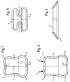
- the cross section of the impact protection beam according to the invention is from FIG. 1 in the undeformed Condition visible.
- the impact protection carrier consists of a pressure belt 1 with a concave shape, the one with side elbows 2, 3 with side bars 4, 5 is also connected by concave shape, which by arc pieces 6, 7 in the Go over flat tension belt 8.
- the tension belt 8 is wider than the compression belt 1.
- In the central area of the tension belt 8 are the side edges of the sheet metal strip, that has been deformed into the profile shown in FIG. 1 in the rolling process with one another welded.
- the profile according to the invention is symmetrical to plane A. Because of the wider Design of the tension belt 8, the neutral fiber in the plane B, the closer is approximated to the tension belt 8. Work on the upper rounded corner areas 2, 3 in the direction of arrows C in Fig. 2 approximately point-like compressive forces have the concave trained webs 4, 5 endeavor to migrate to the outside. It forms This results in an almost almost trapezoidal profile, which is due to the stretching the webs have a higher section modulus than the initial cross section. Increased with increasing deformation under the influence of compressive forces the curvature in the pressure belt 4 and the lateral webs 3, 4 bulge increasingly inward and finally take the one shown in Fig. 3, folded accordion-shaped shape.
- the carrier according to the invention is attached to a door frame, for example by connecting the tension belt with the inner door panel in one Welding or mechanical joining processes.
- FIG. 4 shows a perspective view of the impact protection beam according to FIG. 1, the ends of which are cut at an angle for the purpose of installation in a door frame are. For the sake of simplicity, these are shown in the schematic representation concave deformations of the pressure belt and the lateral webs are not shown.
Abstract
Description
- Fig. 1
- einen Querschnitt durch den erfindungsgemäßen Rammschutzträger,
- Fig. 2
- den Querschnitt des Rammschutzträgers nach Fig. 1 unter einer geringen Belastung eines auf die gewölbten Eckbereiche des Druckgurts wirkenden Stempels,
- Fig. 3
- die Verformung des Querschnitts des Rammschutzträgers nach den Fig. 1 und 2 unter Einwirkung von hoher Belastung durch einen Stempel und
- Fig. 4
- eine perspektivische Ansicht des Rammschutzträgers nach Fig. 1 mit beschnittenen Enden.
Claims (5)
- Rammschutzträger zum Aufprallschutz von Kraftfahrzeugen, z.B. für Türen oder Seitenwände oder Stoßstangen, bestehend aus einem Hohlprofil mit einem Druckgurt (1) und einem Zuggurt (8)
dadurch gekennzeichnet,
daß der Träger durch Rollformen aus einem Metallband hergestellt ist und die Druck- und Zuggurte (1, 8) durch seitliche Stege (4, 5) mit konkaver Form miteinander verbunden sind, daß der Zuggurt (8) breiter ausgebildet ist als der Druckgurt und daß der Druckgurt (1) eine konkave Form besitzt. - Rammschutzträger nach Anspruch 1, dadurch gekennzeichnet, daß die Übergänge zwischen den Druck- und Zuggurten (1, 8) und den Stegen (4, 5) durch Rundungen (2, 3, 6, 7) gebildet sind.
- Rammschutzträger nach Anspruch 1 oder 2, dadurch gekennzeichnet, daß die die Seitenkanten des Metallbandes verbindende Naht im mittleren Bereich des Druckgurts (1) liegt.
- Rammschutzträger nach einem der Ansprüche 1 bis 3, dadurch gekennzeichnet, daß das Metallband aus Blech gleicher Dicke besteht.
- Rammschutzträger nach einem der Ansprüche 1 bis 4, dadurch gekennzeichnet, daß das Metallband aus Stahlblech besteht.
Applications Claiming Priority (2)
| Application Number | Priority Date | Filing Date | Title |
|---|---|---|---|
| DE19854185A DE19854185A1 (de) | 1998-11-24 | 1998-11-24 | Rammschutzträger |
| DE19854185 | 1998-11-24 |
Publications (3)
| Publication Number | Publication Date |
|---|---|
| EP1004465A2 true EP1004465A2 (de) | 2000-05-31 |
| EP1004465A3 EP1004465A3 (de) | 2002-08-14 |
| EP1004465B1 EP1004465B1 (de) | 2005-06-08 |
Family
ID=7888847
Family Applications (1)
| Application Number | Title | Priority Date | Filing Date |
|---|---|---|---|
| EP99122584A Expired - Lifetime EP1004465B1 (de) | 1998-11-24 | 1999-11-12 | Rammschutzträger |
Country Status (4)
| Country | Link |
|---|---|
| EP (1) | EP1004465B1 (de) |
| CZ (1) | CZ295134B6 (de) |
| DE (2) | DE19854185A1 (de) |
| ES (1) | ES2244140T3 (de) |
Cited By (2)
| Publication number | Priority date | Publication date | Assignee | Title |
|---|---|---|---|---|
| EP1705043A3 (de) * | 2005-03-21 | 2008-12-10 | DURA Automotive Body & Glass Systems GmbH | Seitenaufprallträger für ein Kraftfahrzeug |
| CN103112419A (zh) * | 2013-02-19 | 2013-05-22 | 力帆实业(集团)股份有限公司 | 轿车车门防撞杆 |
Families Citing this family (6)
| Publication number | Priority date | Publication date | Assignee | Title |
|---|---|---|---|---|
| US6540276B2 (en) | 2000-11-09 | 2003-04-01 | Aisin Seiki Kabushiki Kaisha | Bumper reinforcement structure |
| DE10150625B4 (de) * | 2001-10-12 | 2005-04-07 | Suspa Holding Gmbh | Schutzvorrichtung für Kraftfahrzeuge |
| DE10150624B4 (de) * | 2001-10-12 | 2005-08-11 | Suspa Holding Gmbh | Schutzvorrichtung für Kraftfahrzeuge |
| DE10354723B4 (de) * | 2003-11-22 | 2008-02-28 | Institut Für Verbundwerkstoffe Gmbh | Stoßfängerquerträger für ein Fahrzeug |
| DE102009034080A1 (de) | 2009-04-01 | 2010-10-14 | Dura Automotive Body & Glass Systems Gmbh | Seitenaufprallträger für eine Türe oder Klappe eines Kraftfahrzeugs |
| DE102009057454B4 (de) * | 2009-12-09 | 2016-07-28 | Frank Palm | Rohrprofil |
Citations (5)
| Publication number | Priority date | Publication date | Assignee | Title |
|---|---|---|---|---|
| DE3606024A1 (de) | 1986-02-25 | 1987-08-27 | Aluminium Walzwerke Singen | Fahrzeugtuer mit aufprallprofil |
| EP0390769A1 (de) | 1989-03-30 | 1990-10-03 | Austria Metall Aktiengesellschaft | Rammschutzträger für Türen und Seitenwände von Kraftfahrzeugkarosserien |
| DE4303435A1 (de) | 1993-02-05 | 1994-08-11 | Austria Metall | Rammschutzträger für Türen und Seitenwände von Kraftfahrzeugkarosserien |
| US5580120A (en) | 1995-02-23 | 1996-12-03 | Mascotech Tubular Products, Inc. | Vehicle door intrusion beam |
| DE19756459A1 (de) | 1997-11-25 | 1999-06-02 | Wagon Automotive Gmbh | Aufprallträger für eine Kraftfahrzeugtür |
Family Cites Families (5)
| Publication number | Priority date | Publication date | Assignee | Title |
|---|---|---|---|---|
| US5232261A (en) * | 1992-06-04 | 1993-08-03 | Nhk Spring Co., Ltd. | Door impact beam for an automobile |
| DE9218268U1 (de) * | 1992-06-05 | 1993-10-21 | Austria Metall Ag Braunau | Verformungshohlkörper |
| DE4306824A1 (de) * | 1993-03-04 | 1994-09-08 | Norsk Hydro As | Aufprallträger zur Versteifung eines Kraftfahrzeugwandteils und Wandteil, welches mit einem solchen Aufprallträger ausgestattet ist |
| SE503450C2 (sv) * | 1994-01-26 | 1996-06-17 | Plannja Hardtech Ab | Stötfångarbalk |
| DE4438869A1 (de) * | 1994-11-03 | 1996-05-09 | Aeroquip Sterling Gmbh | Rammschutzprofil für Kraftfahrzeugtüren und Verfahren zu seiner Herstellung |
-
1998
- 1998-11-24 DE DE19854185A patent/DE19854185A1/de not_active Withdrawn
-
1999
- 1999-11-12 EP EP99122584A patent/EP1004465B1/de not_active Expired - Lifetime
- 1999-11-12 DE DE59912146T patent/DE59912146D1/de not_active Expired - Lifetime
- 1999-11-12 ES ES99122584T patent/ES2244140T3/es not_active Expired - Lifetime
- 1999-11-19 CZ CZ19994108A patent/CZ295134B6/cs not_active IP Right Cessation
Patent Citations (5)
| Publication number | Priority date | Publication date | Assignee | Title |
|---|---|---|---|---|
| DE3606024A1 (de) | 1986-02-25 | 1987-08-27 | Aluminium Walzwerke Singen | Fahrzeugtuer mit aufprallprofil |
| EP0390769A1 (de) | 1989-03-30 | 1990-10-03 | Austria Metall Aktiengesellschaft | Rammschutzträger für Türen und Seitenwände von Kraftfahrzeugkarosserien |
| DE4303435A1 (de) | 1993-02-05 | 1994-08-11 | Austria Metall | Rammschutzträger für Türen und Seitenwände von Kraftfahrzeugkarosserien |
| US5580120A (en) | 1995-02-23 | 1996-12-03 | Mascotech Tubular Products, Inc. | Vehicle door intrusion beam |
| DE19756459A1 (de) | 1997-11-25 | 1999-06-02 | Wagon Automotive Gmbh | Aufprallträger für eine Kraftfahrzeugtür |
Cited By (4)
| Publication number | Priority date | Publication date | Assignee | Title |
|---|---|---|---|---|
| EP1705043A3 (de) * | 2005-03-21 | 2008-12-10 | DURA Automotive Body & Glass Systems GmbH | Seitenaufprallträger für ein Kraftfahrzeug |
| US7497504B2 (en) | 2005-03-21 | 2009-03-03 | Dura Automotive Body & Glass Systems Gmbh | Side-on collision beam for a motor vehicle |
| CN103112419A (zh) * | 2013-02-19 | 2013-05-22 | 力帆实业(集团)股份有限公司 | 轿车车门防撞杆 |
| CN103112419B (zh) * | 2013-02-19 | 2015-02-25 | 力帆实业(集团)股份有限公司 | 轿车车门防撞杆 |
Also Published As
| Publication number | Publication date |
|---|---|
| DE19854185A1 (de) | 2000-05-31 |
| CZ410899A3 (cs) | 2000-06-14 |
| DE59912146D1 (de) | 2005-07-14 |
| ES2244140T3 (es) | 2005-12-01 |
| CZ295134B6 (cs) | 2005-05-18 |
| EP1004465B1 (de) | 2005-06-08 |
| EP1004465A3 (de) | 2002-08-14 |
Similar Documents
| Publication | Publication Date | Title |
|---|---|---|
| DE102005057429B4 (de) | Crashbox | |
| DE60005468T2 (de) | Kraftfahrzeugstossstangenträger | |
| DE102011053158B4 (de) | Stoßfängersystem für ein Kraftfahrzeug | |
| DE10108287B4 (de) | Karosseriestruktur | |
| EP0869019B1 (de) | Seitenaufprallträger für Kfz-Türen | |
| DE10003878B4 (de) | Zusatzelement | |
| DE19849358C2 (de) | Stoßfänger für Kraftfahrzeuge | |
| DE2636655A1 (de) | Hohltraeger fuer fahrzeuge und verfahren zu seiner herstellung | |
| DE69931422T2 (de) | Aufprallträger für Kraftfahrzeuge | |
| DE10013527A1 (de) | Verfahren zur Herstellung eines Bestandteil eines Stoßfängers bildenden stählernen Querträgers für Kraftfahrzeuge und Querträger | |
| EP1533192A1 (de) | Stossfängersystem | |
| EP1424232A1 (de) | Profilrahmen | |
| DE10132028A1 (de) | Kraftfahrzeugtürverstärkungselement | |
| DE60005737T2 (de) | Stossfängeranordnung für Fahrzeuge | |
| DE102008029634A1 (de) | Stoßfänger mit Halterungen für ein Fahrzeug | |
| DE19756459A1 (de) | Aufprallträger für eine Kraftfahrzeugtür | |
| EP3519278A1 (de) | Strukturbauteil für eine kraftfahrzeugkarosserie | |
| WO2020035397A1 (de) | Stossfänger für ein kraftfahrzeug | |
| DE19540787B4 (de) | Aufpralldämpfer sowie Verfahren zu seiner Herstellung | |
| WO2021043896A1 (de) | STOßFÄNGERQUERTRÄGER FÜR EIN KRAFTFAHRZEUG | |
| EP1004465B1 (de) | Rammschutzträger | |
| DE10048902C1 (de) | Stossfängeranordnung | |
| DE102015114943A1 (de) | Verfahren zur Herstellung eines geschlossenen Hohlprofils für eine Fahrzeugachse | |
| DE10309636A1 (de) | Karosserieträger mit einer den Verformungsverlauf bei einem Aufprall beeinflussenden Nebenform | |
| DE4335029C2 (de) | A-Säulenverbindungsteil und Verfahren zu seiner Herstellung |
Legal Events
| Date | Code | Title | Description |
|---|---|---|---|
| PUAI | Public reference made under article 153(3) epc to a published international application that has entered the european phase |
Free format text: ORIGINAL CODE: 0009012 |
|
| AK | Designated contracting states |
Kind code of ref document: A2 Designated state(s): AT BE CH CY DE DK ES FI FR GB GR IE IT LI LU MC NL PT SE |
|
| AX | Request for extension of the european patent |
Free format text: AL;LT;LV;MK;RO;SI |
|
| PUAL | Search report despatched |
Free format text: ORIGINAL CODE: 0009013 |
|
| AK | Designated contracting states |
Kind code of ref document: A3 Designated state(s): AT BE CH CY DE DK ES FI FR GB GR IE IT LI LU MC NL PT SE |
|
| AX | Request for extension of the european patent |
Free format text: AL;LT;LV;MK;RO;SI |
|
| 17P | Request for examination filed |
Effective date: 20020905 |
|
| 17Q | First examination report despatched |
Effective date: 20021022 |
|
| AKX | Designation fees paid |
Designated state(s): DE ES FR GB IT |
|
| GRAP | Despatch of communication of intention to grant a patent |
Free format text: ORIGINAL CODE: EPIDOSNIGR1 |
|
| GRAS | Grant fee paid |
Free format text: ORIGINAL CODE: EPIDOSNIGR3 |
|
| GRAA | (expected) grant |
Free format text: ORIGINAL CODE: 0009210 |
|
| AK | Designated contracting states |
Kind code of ref document: B1 Designated state(s): DE ES FR GB IT |
|
| REG | Reference to a national code |
Ref country code: GB Ref legal event code: FG4D Free format text: NOT ENGLISH |
|
| REF | Corresponds to: |
Ref document number: 59912146 Country of ref document: DE Date of ref document: 20050714 Kind code of ref document: P |
|
| GBT | Gb: translation of ep patent filed (gb section 77(6)(a)/1977) |
Effective date: 20050919 |
|
| PG25 | Lapsed in a contracting state [announced via postgrant information from national office to epo] |
Ref country code: IT Free format text: LAPSE BECAUSE OF NON-PAYMENT OF DUE FEES Effective date: 20051112 |
|
| REG | Reference to a national code |
Ref country code: ES Ref legal event code: FG2A Ref document number: 2244140 Country of ref document: ES Kind code of ref document: T3 |
|
| ET | Fr: translation filed | ||
| PLBE | No opposition filed within time limit |
Free format text: ORIGINAL CODE: 0009261 |
|
| STAA | Information on the status of an ep patent application or granted ep patent |
Free format text: STATUS: NO OPPOSITION FILED WITHIN TIME LIMIT |
|
| 26N | No opposition filed |
Effective date: 20060309 |
|
| REG | Reference to a national code |
Ref country code: FR Ref legal event code: ST Effective date: 20080131 |
|
| REG | Reference to a national code |
Ref country code: FR Ref legal event code: D3 |
|
| PGFP | Annual fee paid to national office [announced via postgrant information from national office to epo] |
Ref country code: FR Payment date: 20101202 Year of fee payment: 12 |
|
| PGFP | Annual fee paid to national office [announced via postgrant information from national office to epo] |
Ref country code: GB Payment date: 20101124 Year of fee payment: 12 |
|
| PGFP | Annual fee paid to national office [announced via postgrant information from national office to epo] |
Ref country code: ES Payment date: 20101125 Year of fee payment: 12 |
|
| GBPC | Gb: european patent ceased through non-payment of renewal fee |
Effective date: 20111112 |
|
| REG | Reference to a national code |
Ref country code: FR Ref legal event code: ST Effective date: 20120731 |
|
| PG25 | Lapsed in a contracting state [announced via postgrant information from national office to epo] |
Ref country code: GB Free format text: LAPSE BECAUSE OF NON-PAYMENT OF DUE FEES Effective date: 20111112 |
|
| PG25 | Lapsed in a contracting state [announced via postgrant information from national office to epo] |
Ref country code: FR Free format text: LAPSE BECAUSE OF NON-PAYMENT OF DUE FEES Effective date: 20111130 |
|
| REG | Reference to a national code |
Ref country code: ES Ref legal event code: FD2A Effective date: 20130604 |
|
| PG25 | Lapsed in a contracting state [announced via postgrant information from national office to epo] |
Ref country code: ES Free format text: LAPSE BECAUSE OF NON-PAYMENT OF DUE FEES Effective date: 20111113 |
|
| REG | Reference to a national code |
Ref country code: DE Ref legal event code: R082 Ref document number: 59912146 Country of ref document: DE Representative=s name: LORENZ SEIDLER GOSSEL RECHTSANWAELTE PATENTANW, DE Ref country code: DE Ref legal event code: R081 Ref document number: 59912146 Country of ref document: DE Owner name: DURA AUTOMOTIVE HOLDINGS U.K., LTD., CASTLE VA, GB Free format text: FORMER OWNER: DURA AUTOMOTIVE BODY & GLASS SYSTEMS GMBH & CO. KG, 58840 PLETTENBERG, DE |
|
| PGFP | Annual fee paid to national office [announced via postgrant information from national office to epo] |
Ref country code: DE Payment date: 20171129 Year of fee payment: 19 |
|
| REG | Reference to a national code |
Ref country code: DE Ref legal event code: R119 Ref document number: 59912146 Country of ref document: DE |
|
| PG25 | Lapsed in a contracting state [announced via postgrant information from national office to epo] |
Ref country code: DE Free format text: LAPSE BECAUSE OF NON-PAYMENT OF DUE FEES Effective date: 20190601 |