EP1003246B1 - Modulares Steckverbindersystem - Google Patents
Modulares Steckverbindersystem Download PDFInfo
- Publication number
- EP1003246B1 EP1003246B1 EP99121831A EP99121831A EP1003246B1 EP 1003246 B1 EP1003246 B1 EP 1003246B1 EP 99121831 A EP99121831 A EP 99121831A EP 99121831 A EP99121831 A EP 99121831A EP 1003246 B1 EP1003246 B1 EP 1003246B1
- Authority
- EP
- European Patent Office
- Prior art keywords
- plug
- connection system
- support plates
- module
- socket
- Prior art date
- Legal status (The legal status is an assumption and is not a legal conclusion. Google has not performed a legal analysis and makes no representation as to the accuracy of the status listed.)
- Expired - Lifetime
Links
- 238000003780 insertion Methods 0.000 claims description 10
- 230000037431 insertion Effects 0.000 claims description 10
- 239000004020 conductor Substances 0.000 claims description 6
- 239000002184 metal Substances 0.000 abstract description 13
- 230000000712 assembly Effects 0.000 abstract description 11
- 238000000429 assembly Methods 0.000 abstract description 11
- 238000010276 construction Methods 0.000 description 3
- 238000005553 drilling Methods 0.000 description 2
- 239000002360 explosive Substances 0.000 description 2
- 230000003993 interaction Effects 0.000 description 2
- 230000006978 adaptation Effects 0.000 description 1
- 230000015572 biosynthetic process Effects 0.000 description 1
- 230000000694 effects Effects 0.000 description 1
- 238000009434 installation Methods 0.000 description 1
- 238000004519 manufacturing process Methods 0.000 description 1
- 238000000034 method Methods 0.000 description 1
Images


Classifications
-
- H—ELECTRICITY
- H01—ELECTRIC ELEMENTS
- H01R—ELECTRICALLY-CONDUCTIVE CONNECTIONS; STRUCTURAL ASSOCIATIONS OF A PLURALITY OF MUTUALLY-INSULATED ELECTRICAL CONNECTING ELEMENTS; COUPLING DEVICES; CURRENT COLLECTORS
- H01R13/00—Details of coupling devices of the kinds covered by groups H01R12/70 or H01R24/00 - H01R33/00
- H01R13/46—Bases; Cases
- H01R13/502—Bases; Cases composed of different pieces
- H01R13/506—Bases; Cases composed of different pieces assembled by snap action of the parts
-
- H—ELECTRICITY
- H01—ELECTRIC ELEMENTS
- H01R—ELECTRICALLY-CONDUCTIVE CONNECTIONS; STRUCTURAL ASSOCIATIONS OF A PLURALITY OF MUTUALLY-INSULATED ELECTRICAL CONNECTING ELEMENTS; COUPLING DEVICES; CURRENT COLLECTORS
- H01R13/00—Details of coupling devices of the kinds covered by groups H01R12/70 or H01R24/00 - H01R33/00
- H01R13/46—Bases; Cases
- H01R13/514—Bases; Cases composed as a modular blocks or assembly, i.e. composed of co-operating parts provided with contact members or holding contact members between them
Definitions
- the invention relates to a modular connector system with a socket and a Plug part, each having a base frame, one in cross section substantially U-shaped recess for receiving at least one provided with plug contacts Single modules included.
- a generic connector system is known from DE 29812500. That in this Illustrated connector system comprises a support or base frame, the longitudinal Has frame strips and contains several modules, each at a first Longitudinal edge of the frame strips are supported. These are independent locking elements provided, which are latching or clamping on the modules mountable and these block a second longitudinal edge opposite the first longitudinal edge. The locking elements are formed by strips that extend over several modules and attack at each of these modules. These include the strips projections, which in accordance with Border recesses of the modules.
- the modules that can be used in the support frame each are for a particular purpose e.g. adapted as male or female part, but have few common parts. Although realized in principle a modular structure The individual modules are fundamentally different in their structure. A standardization The elements of the individual modules do not take place.
- the invention therefore sets in the task of an easy to install and produce modular To provide connector system, in which, even the individual modules largely made several times consist of usable standard elements.
- each individual module can be plugged together and in the assembled state, the module housing forming plastic carrier plates between which portions of metal assemblies for forming the plug contacts can be used, wherein the plastic carrier plates and the plastic carrier plates rimmed sections of the metal assemblies socket side and plug side structurally the same.
- the individual modules consist of an assembly, each one of two plastic carrier plates having existing housing, which for receiving the metal assemblies is designed.
- the housing of the individual modules - and preferably also the spring elements of the metal assemblies - are designed to be identical in terms of plug and socket.
- the carrier plates each have a plate-like base portion and a formed on the base section contour for receiving the metal assemblies and the Formation of openings and / or holes for insertion of the conductor and / or a Operating tool in the single module, wherein preferably further provided in that the openings for inserting the conductor into the individual module are opposite to the one Plug-in direction of the connector system inclined guide contour for easy guidance the screwdriver in the single module and for easy opening of the springs of the metal assemblies to have.
- the base frame comprises on its outer sides Locking elements such as dovetails or snap hooks for inserting the Base frame in a holding element.
- Locking elements such as dovetails or snap hooks for inserting the Base frame in a holding element.
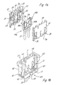
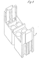
- Fig. 1a shows an exploded view of a single module 1 for insertion into the U-shaped recess 3 of a designed as a pin adapter base or holding frame 5 of FIG. 1b.
- Each individual module 1 has two identical, plug-together support plates 7a, 7b, between which spring elements 9a, 9b and integrally formed on the spring elements 9 busbars 10a, 10b of two metal assemblies 11a, 11b are settable.
- the carrier plates 7 on their sides facing each other with a plate-like base portion 13th and a formed on the base portion contour 15 for receiving the metal assemblies 11 and to form bore-like openings 17, 19 provided.
- the openings 17, 19 are used to insert the (not shown here) conductor - opening 17 - and / or one Screwdriver for opening the spring element 9 - openings 19.
- the contour 15 includes In addition, a plurality of pin-like projections 21, which in the assembled state of Single modules fixed in corresponding holes 23 of the opposite support plate. 7 intervention.
- the contour 15 comprises in the left in this figure
- Part of the support plate 7 also has a rail-like, inclined to the main insertion axis S projection 25, which in fitting a further support plate 7 in a correspondingly shaped Groove 27 engages and when inserting a screwdriver into the channels 19 a problem Opening the spring elements 9 allowed (see also Fig. 2b).
- the contour 15 also forms lower openings in the assembled state of the carrier plates 7 29, which extend substantially in the insertion direction.
- spring lugs 31 are formed, which are used for resilient installation of Plug pins 33 or sockets 33, 35 (see FIGS. 1 and 2) and to compensate for serve different thermal expansion behavior of the plastic and metal components.
- the busbar and the tension spring portion of the metal assembly 11 are around webs 37 laid with rounded ends.
- the entire carrier plate is executed hermaphroditic.
- the webs 37 are manufactured hermaphroditic.
- the webs 37 are manufacturedg.
- the support plates 7 further comprise on their outer sides lateral snap hooks 39 for locking the individual modules 7 on cooperating with the snap hooks 39 undercuts 41 the base frame 5,51.
- For safe guidance of the individual modules on the base frame ensures the interaction of extending in the insertion direction S 'grooves 42 in Base frame 5 and guide projections 44 on the individual modules.
- the base frame 5 are formed such that they in turn as elements of a parent (not shown here) system can be used.
- the basic frame has this on its outer sides via locking elements, in Figs. 1 and 2 as snap closures 46 are formed for insertion of the connector in a holding element.
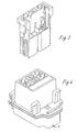
- Fig. 1b illustrates the engagement of the individual module 1 in the frame part 5.
- the lateral Snap locks 46 on the frame part 5 allow the insertion of the frame part 5 in a parent (not shown here) holding system.
- each individual module 1 At the bottom base of the U-shaped Recess is formed each individual module 1 by a holding frame Web 43, which engages in notches 45 in the individual modules 1, centered in the individual module 1.
- openings 47 are also provided, through which the connector pins 33 protrude beyond the base side of the U to the outside.
- the Base side of the U-shaped recess 3 thus forms a pin adapter portion 49th
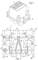
- FIGS. 2 and 3 differs from that of FIG. 1 in particular in that integrally formed on the base frame 5 in the insertion direction a female adapter portion 51 is.
- the female adapter portion 51 is in turn with the openings 47 provided, in which in this embodiment, however, the Stekkerbuchsen 35 are guided.
- To protect the connector system corresponds to the length of the lower socket adapter portion approximately the extension of the sockets. That lie the bases of the pin and socket adapter section in the assembled one State together. Increases the centering effect between male and female parts thereby that the side walls 53 of the openings 47 of the plug part on the lower Projecting base side of the U and when merging the male and female parts in engage the female part or the female adapter portion 51.
- the other embodiments serve to illustrate the versatile applications the single modules 1 in module plug systems of various kinds.
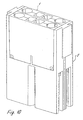
- FIGS. 4 and 5 show analogously to FIGS. 1 and 2, a connector adapter pin S and a connector adapter socket B, each with three individual modules 1 are providable.
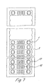
- Fig. 7 shows a holding frame 7 for receiving a plurality of individual modules.
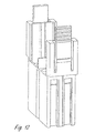
- Fig. 8 to 10 show the possibility of the holding frame 7 with outer dovetail elements to Mistake.
- Fig. 11 to 13 illustrate different possibilities of realization of the locking elements of the basic frame.
Landscapes
- Connector Housings Or Holding Contact Members (AREA)
- Coupling Device And Connection With Printed Circuit (AREA)
- Multi-Conductor Connections (AREA)
Description
- Fig. 1a
- eine Sprengansicht eines Einzelmodules;
- Fig. 1b
- eine perspektivische Ansicht eines als Steckadapter ausgebildeten Grundrahmens, in welchen das Einzelmodul aus Fig. 1a eingesetzt ist;
- Fig. 2a
- eine Sprengansicht eines weiteren Einzelmodules mit Steckerbuchsen;
- Fig. 2b
- eine perspektivische Ansicht eines als Buchsenadapter ausgebildeten Grundrahmens, in welchen das Einzelmodul aus Fig. 2a eingesetzt ist;
- Fig. 3
- eine weitere perspektivische Ansicht des als Buchsenadapter ausgebildeten Grundrahmens aus Fig. 2 mit einem vollständigen Einzelmodul;
- Fig. 4
- eine perspektivische Ansicht eines weiteren Ausführungsbeispiels eines als Steckadapter ausgebildeten Grundrahmens mit Einzelmodulen;
- Fig. 5
- eine perspektivische Ansicht eines weiteren Ausführungsbeispiels eines als Buchsenadapter ausgebildeten Grundrahmens mit Einzelmodulen;
- Fig. 6
- eine Draufsicht auf eine Trägerplatte eines Einzelmodules;
- Fig. 7
- eine Draufsicht auf einen weiteren Grundrahmen mit Einzelmodulen;
- Fig. 8 bis 13
- verschiedene Ansichten weiterer Ausführungsbeispiele der Erfindung.
- Einzelmodul
- 1
- Ausnehmung
- 3
- Grundrahmen
- 5
- Trägerplatten
- 7a,7b
- Federelemente
- 9a, 9b
- Stromschienen
- 10a, 10b
- Metallbaugruppen
- 11a, 11b
- Grundabschnitt
- 13
- Kontur
- 15
- Öffnungen
- 17, 19
- stiftartige Vorsprünge
- 21
- Bohrungen
- 23
- Vorsprung
- 25
- Nut
- 27
- Öffnungen
- 29
- Federnasen
- 31
- Steckerstifte
- 33
- Steckerbuchsen
- 35
- Stege
- 37
- Schnapphaken
- 39
- Hinterschneidungen
- 41
- Nuten
- 42
- Steg
- 43
- Führungsvorsprünge
- 44
- Einschnitte
- 45
- Schnappverschlüsse
- 46
- Bohrungen
- 47
- Stiftadapterabschnitt
- 49
- Buchsenadapterabschnitt
- 51
- Seitenwandungen
- 53
- Schwalbenschanz
- 55
- Schnappvorsprung
- 57
Claims (8)
- Modulares Steckverbindersystem mit einem Buchsen- und einem Steckerteil, die jeweils einen Grundrahmen (5) aufweisen, der eine im Querschnitt im wesentlichen U-förmige Ausnehmung (3) zur Aufnahme wenigstens eines mit Steckkontakten versehenen Einzelmodules (1) umfaßt,
dadurch gekennzeichnet, daß
jedes Einzelmodul (1) zwei zusammensteckbare und im zusammengesetzten Zustand das Modulgehäuse ausbildende Kunststoff-Trägerplatten (7) aufweist, zwischen welche Abschnitte von Metallbaugruppen (11) zur Ausbildung der Steckkontakte einsetzbar sind, wobei die Kunststoff-Trägerplatten (7) und die von den Kunststoff-Trägerplatten (7) eingefaßten Abschnitte der Metallbaugruppen (11) buchsenseitig und steckerseitig baulich gleich sind (hermaphroditisch). - Modulares Steckverbindersystem nach Anspruch 1, dadurch gekennzeichnet, daß die Metallbaugruppen (11) jeweils ein zwischen den beiden Trägerplatten (7) liegendes Federelement (9) mit daran angeformter Stromschiene (10) zur klemmbaren Einführen eines Leiters aufweisen, wobei Federelement und Stromschiene stecker- und buchsenseitig baulich gleich ausgeführt sind und Stege (37) der Trägerplatten umfassen.
- Modulares Steckverbindersystem nach Anspruch 1 oder 2, dadurch gekennzeichnet, daß die Trägerplatten (7) jeweils einen plattenartigen Grundabschnitt (13) und eine auf den Grundabschnitt aufgeformte Kontur (15) zur Aufnahme der Metallbaugruppen (11) und zur Ausbildung von Öffnungen und/oder Bohrungen zum Einschieben des Leiters und/oder eines Betätigungswerkzeuges in das Einzelmodul (1) aufweisen.
- Modulares Steckverbindersystem nach einem der vorstehenden Ansprüche, dadurch gekennzeichnet, daß die Öffnungen zum Einschieben des Leiters in das Einzelmodul eine gegenüber der Steckrichtung des Steckverbindersystemes geneigte Führungskontur (Vorsprung 25) zum Führen des Schraubendrehers im Einzelmodul (1) aufweisen.
- Modulares Steckverbindersystem nach einem der vorstehenden Ansprüche, dadurch gekennzeichnet, daß die Trägerplatten (7) seitliche Schnapphaken (39) zur Verriegelung der Einzelmodule an mit den Schnapphaken zusammenwirkenden Hinterschneidungen (41) der Grundrahmen (5) aufweisen.
- Modulares Steckverbindersystem nach einem der vorstehenden Ansprüche, dadurch gekennzeichnet, daß der Grundrahmen (5) sich in Steckrichtung erstreckende Nuten zur Aufnahme von Führungsvorsprüngen der Einzelmodule aufweist.
- Modulares Steckverbindersystem nach einem der vorstehenden Ansprüche, dadurch gekennzeichnet, daß der Grundrahmen (5) an seinen Außenseiten Verriegelungselemente wie Schwalbenschwänze (55) oder Schnapphaken (46, 57) zum Einsetzen des Grundrahmens in ein Halteelement aufweisen.
- Modulares Steckverbindersystem nach einem der vorstehenden Ansprüche, dadurch gekennzeichnet, daß an den Grundrahmen (5) in Steckrichtung ein Stiftadapterabschnitt (49) oder ein Buchsenadapterabschnitt (51) angeformt ist.
Applications Claiming Priority (2)
| Application Number | Priority Date | Filing Date | Title |
|---|---|---|---|
| DE29820771U DE29820771U1 (de) | 1998-11-20 | 1998-11-20 | Modulares Steckverbindersystem |
| DE29820771U | 1998-11-20 |
Publications (3)
| Publication Number | Publication Date |
|---|---|
| EP1003246A2 EP1003246A2 (de) | 2000-05-24 |
| EP1003246A3 EP1003246A3 (de) | 2002-01-16 |
| EP1003246B1 true EP1003246B1 (de) | 2005-02-09 |
Family
ID=8065603
Family Applications (1)
| Application Number | Title | Priority Date | Filing Date |
|---|---|---|---|
| EP99121831A Expired - Lifetime EP1003246B1 (de) | 1998-11-20 | 1999-11-04 | Modulares Steckverbindersystem |
Country Status (3)
| Country | Link |
|---|---|
| EP (1) | EP1003246B1 (de) |
| AT (1) | ATE289119T1 (de) |
| DE (2) | DE29820771U1 (de) |
Cited By (1)
| Publication number | Priority date | Publication date | Assignee | Title |
|---|---|---|---|---|
| WO2007111458A1 (en) * | 2006-03-29 | 2007-10-04 | K.I.C.A Inc. | Adaptor for connecting plug to different type of power outlet |
Families Citing this family (5)
| Publication number | Priority date | Publication date | Assignee | Title |
|---|---|---|---|---|
| DE20117856U1 (de) * | 2001-11-02 | 2003-03-13 | Weidmüller Interface GmbH & Co., 32760 Detmold | Modulares Steckverbindersystem |
| DE202004000523U1 (de) * | 2004-01-15 | 2005-05-25 | Weidmüller Interface GmbH & Co. KG | Anschlußsystem zum Anschluß elektrischer Leiter an ein elektrisches Gerät |
| DE202005015465U1 (de) * | 2005-10-01 | 2007-02-15 | Weidmüller Interface GmbH & Co. KG | Steckverbindersystem aus schweren elektrischen Steckverbindern |
| DE102009037800A1 (de) * | 2009-08-18 | 2011-02-24 | Bircher Reglomat Ag | Rucksacksteckmodul für einen Schalter |
| DE202009016326U1 (de) * | 2009-12-01 | 2011-04-14 | Weidmüller Interface GmbH & Co. KG | Steckeranordnung |
Family Cites Families (8)
| Publication number | Priority date | Publication date | Assignee | Title |
|---|---|---|---|---|
| US3457640A (en) | 1964-12-17 | 1969-07-29 | Western Electric Co | Methods of fabricating an electrical coupler |
| US3854790A (en) | 1973-09-17 | 1974-12-17 | Bunker Ramo | Electrical connector assembly |
| FR2497413A1 (fr) * | 1980-12-30 | 1982-07-02 | Labinal | Connecteurs electriques a combinaison |
| US5308258A (en) * | 1993-01-29 | 1994-05-03 | International Business Machines Corporation | Planar modular interconnect system |
| DE9312002U1 (de) | 1993-08-11 | 1993-09-30 | Siemens AG, 80333 München | Um 90¤ abgewinkelter Steckverbinder für die Einpreßtechnik |
| DE29508095U1 (de) * | 1995-05-17 | 1995-07-20 | HTS-Elektrotechnik GmbH, 53819 Neunkirchen-Seelscheid | Modulares Steckverbindersystem |
| DE19610958C2 (de) | 1996-03-20 | 1999-02-04 | Weidmueller Interface | Mehrpoliger Steckverbinder mit Zugfederanschlüssen |
| DE29812500U1 (de) | 1998-07-14 | 1998-09-10 | Industria Lombarda Materiale Elettrico I.L.M.E. S.P.A., Mailand/Milano | Modularer Steckverbinder |
-
1998
- 1998-11-20 DE DE29820771U patent/DE29820771U1/de not_active Expired - Lifetime
-
1999
- 1999-11-04 AT AT99121831T patent/ATE289119T1/de not_active IP Right Cessation
- 1999-11-04 DE DE59911590T patent/DE59911590D1/de not_active Expired - Lifetime
- 1999-11-04 EP EP99121831A patent/EP1003246B1/de not_active Expired - Lifetime
Cited By (3)
| Publication number | Priority date | Publication date | Assignee | Title |
|---|---|---|---|---|
| WO2007111458A1 (en) * | 2006-03-29 | 2007-10-04 | K.I.C.A Inc. | Adaptor for connecting plug to different type of power outlet |
| GB2442930A (en) * | 2006-03-29 | 2008-04-16 | K I C A Inc | Adaptor for connecting plug to different type of power outlet |
| GB2442930B (en) * | 2006-03-29 | 2011-05-18 | K I C A Inc | Adaptor for connecting plug to different type of power outlet |
Also Published As
| Publication number | Publication date |
|---|---|
| DE29820771U1 (de) | 1999-01-14 |
| EP1003246A2 (de) | 2000-05-24 |
| ATE289119T1 (de) | 2005-02-15 |
| EP1003246A3 (de) | 2002-01-16 |
| DE59911590D1 (de) | 2005-03-17 |
Similar Documents
| Publication | Publication Date | Title |
|---|---|---|
| EP2086077A2 (de) | Montagesystem für elektrische und/oder mechanische Komponenten | |
| DE202008015309U1 (de) | Montagesystem für elektrische und/oder mechanische Komponenten | |
| EP0749178A2 (de) | Modulares Steckverbindersystem | |
| EP0762581B1 (de) | Vorrichtung zum Befestigen eines elektrischen Gerätes auf einem Adapter | |
| EP4169130B1 (de) | Modular aufbaubaren steckverbinder | |
| EP0702441A1 (de) | Elektroinstallationsgerät, insbesondere für Kabelkanäle | |
| EP0592712A1 (de) | Steckanschlusssystem für eine elektronische Baugruppe | |
| DE10040651B4 (de) | Elektronisches Gerät mit Daten- und/oder Energiebusverbindung | |
| EP0642197B1 (de) | Geräteträger für elektrische Installationsgeräte | |
| EP1003246B1 (de) | Modulares Steckverbindersystem | |
| EP3644460B1 (de) | Stromschienensystem | |
| DE69300900T2 (de) | Elektrischer Verbinder. | |
| DE29908490U1 (de) | Haltesystem für verschiedene Typen Steckverbinder | |
| DE3442056A1 (de) | Steckverbindervorrichtung | |
| DE60126452T2 (de) | Verbindungsmodulanordnung mit Polarisationsmittel | |
| DE19860961C1 (de) | Elektrisches Gerät mit einer Verbindungseinrichtung zur Verbindung mit einem zweiten elektrischen Gerät | |
| EP0222116B1 (de) | Einbaudose für elektrische Installationsgeräte | |
| EP0451726A1 (de) | Schnellbefestigung für ein elektrisches Installationsgerät | |
| EP0127849B1 (de) | Relais | |
| WO1993006639A1 (de) | Filter-stecker | |
| DE102023105747A1 (de) | Steckverbinder, Halteelement sowie Set aus einem Steckverbinder und einem Halteelement | |
| DE10243313A1 (de) | Kodierbarer Steckverbinder | |
| DE60032856T2 (de) | Halter für modulare Verbinder, insbesondere für Verbinder mit Halbleiterplättchen sowie zusammengesetzter Verbinder | |
| DE10135662A1 (de) | Gerätebecherrahmen für Unterfluranwendungen | |
| DE19624646A1 (de) | Steckverbinder |
Legal Events
| Date | Code | Title | Description |
|---|---|---|---|
| PUAI | Public reference made under article 153(3) epc to a published international application that has entered the european phase |
Free format text: ORIGINAL CODE: 0009012 |
|
| AK | Designated contracting states |
Kind code of ref document: A2 Designated state(s): AT BE CH CY DE DK ES FI FR GB GR IE IT LI LU MC NL PT SE |
|
| AX | Request for extension of the european patent |
Free format text: AL;LT;LV;MK;RO;SI |
|
| PUAL | Search report despatched |
Free format text: ORIGINAL CODE: 0009013 |
|
| AK | Designated contracting states |
Kind code of ref document: A3 Designated state(s): AT BE CH CY DE DK ES FI FR GB GR IE IT LI LU MC NL PT SE |
|
| AX | Request for extension of the european patent |
Free format text: AL;LT;LV;MK;RO;SI |
|
| 17P | Request for examination filed |
Effective date: 20020108 |
|
| AKX | Designation fees paid |
Free format text: AT BE CH CY DE DK ES FI FR GB GR IE IT LI LU MC NL PT SE |
|
| GRAP | Despatch of communication of intention to grant a patent |
Free format text: ORIGINAL CODE: EPIDOSNIGR1 |
|
| GRAS | Grant fee paid |
Free format text: ORIGINAL CODE: EPIDOSNIGR3 |
|
| GRAA | (expected) grant |
Free format text: ORIGINAL CODE: 0009210 |
|
| AK | Designated contracting states |
Kind code of ref document: B1 Designated state(s): AT BE CH CY DE DK ES FI FR GB GR IE IT LI LU MC NL PT SE |
|
| PG25 | Lapsed in a contracting state [announced via postgrant information from national office to epo] |
Ref country code: NL Free format text: LAPSE BECAUSE OF FAILURE TO SUBMIT A TRANSLATION OF THE DESCRIPTION OR TO PAY THE FEE WITHIN THE PRESCRIBED TIME-LIMIT Effective date: 20050209 Ref country code: IE Free format text: LAPSE BECAUSE OF FAILURE TO SUBMIT A TRANSLATION OF THE DESCRIPTION OR TO PAY THE FEE WITHIN THE PRESCRIBED TIME-LIMIT Effective date: 20050209 Ref country code: GB Free format text: LAPSE BECAUSE OF FAILURE TO SUBMIT A TRANSLATION OF THE DESCRIPTION OR TO PAY THE FEE WITHIN THE PRESCRIBED TIME-LIMIT Effective date: 20050209 Ref country code: FR Free format text: LAPSE BECAUSE OF NON-PAYMENT OF DUE FEES Effective date: 20050209 Ref country code: FI Free format text: LAPSE BECAUSE OF FAILURE TO SUBMIT A TRANSLATION OF THE DESCRIPTION OR TO PAY THE FEE WITHIN THE PRESCRIBED TIME-LIMIT Effective date: 20050209 Ref country code: ES Free format text: LAPSE BECAUSE OF FAILURE TO SUBMIT A TRANSLATION OF THE DESCRIPTION OR TO PAY THE FEE WITHIN THE PRESCRIBED TIME-LIMIT Effective date: 20050209 |
|
| REG | Reference to a national code |
Ref country code: GB Ref legal event code: FG4D Free format text: NOT ENGLISH |
|
| REG | Reference to a national code |
Ref country code: CH Ref legal event code: EP |
|
| REG | Reference to a national code |
Ref country code: IE Ref legal event code: FG4D Free format text: GERMAN |
|
| REF | Corresponds to: |
Ref document number: 59911590 Country of ref document: DE Date of ref document: 20050317 Kind code of ref document: P |
|
| PG25 | Lapsed in a contracting state [announced via postgrant information from national office to epo] |
Ref country code: SE Free format text: LAPSE BECAUSE OF FAILURE TO SUBMIT A TRANSLATION OF THE DESCRIPTION OR TO PAY THE FEE WITHIN THE PRESCRIBED TIME-LIMIT Effective date: 20050509 Ref country code: GR Free format text: LAPSE BECAUSE OF FAILURE TO SUBMIT A TRANSLATION OF THE DESCRIPTION OR TO PAY THE FEE WITHIN THE PRESCRIBED TIME-LIMIT Effective date: 20050509 Ref country code: DK Free format text: LAPSE BECAUSE OF FAILURE TO SUBMIT A TRANSLATION OF THE DESCRIPTION OR TO PAY THE FEE WITHIN THE PRESCRIBED TIME-LIMIT Effective date: 20050509 |
|
| NLV1 | Nl: lapsed or annulled due to failure to fulfill the requirements of art. 29p and 29m of the patents act | ||
| GBV | Gb: ep patent (uk) treated as always having been void in accordance with gb section 77(7)/1977 [no translation filed] |
Effective date: 20050209 |
|
| REG | Reference to a national code |
Ref country code: IE Ref legal event code: FD4D |
|
| PG25 | Lapsed in a contracting state [announced via postgrant information from national office to epo] |
Ref country code: CY Free format text: LAPSE BECAUSE OF FAILURE TO SUBMIT A TRANSLATION OF THE DESCRIPTION OR TO PAY THE FEE WITHIN THE PRESCRIBED TIME-LIMIT Effective date: 20051104 Ref country code: AT Free format text: LAPSE BECAUSE OF NON-PAYMENT OF DUE FEES Effective date: 20051104 |
|
| PG25 | Lapsed in a contracting state [announced via postgrant information from national office to epo] |
Ref country code: MC Free format text: LAPSE BECAUSE OF NON-PAYMENT OF DUE FEES Effective date: 20051130 Ref country code: LU Free format text: LAPSE BECAUSE OF NON-PAYMENT OF DUE FEES Effective date: 20051130 Ref country code: LI Free format text: LAPSE BECAUSE OF NON-PAYMENT OF DUE FEES Effective date: 20051130 Ref country code: CH Free format text: LAPSE BECAUSE OF NON-PAYMENT OF DUE FEES Effective date: 20051130 Ref country code: BE Free format text: LAPSE BECAUSE OF NON-PAYMENT OF DUE FEES Effective date: 20051130 |
|
| PLBE | No opposition filed within time limit |
Free format text: ORIGINAL CODE: 0009261 |
|
| STAA | Information on the status of an ep patent application or granted ep patent |
Free format text: STATUS: NO OPPOSITION FILED WITHIN TIME LIMIT |
|
| 26N | No opposition filed |
Effective date: 20051110 |
|
| EN | Fr: translation not filed | ||
| REG | Reference to a national code |
Ref country code: CH Ref legal event code: PL |
|
| BERE | Be: lapsed |
Owner name: WEIDMULLER INTERFACE G.M.B.H. & CO. Effective date: 20051130 |
|
| PG25 | Lapsed in a contracting state [announced via postgrant information from national office to epo] |
Ref country code: PT Free format text: LAPSE BECAUSE OF NON-PAYMENT OF DUE FEES Effective date: 20050709 |
|
| PGFP | Annual fee paid to national office [announced via postgrant information from national office to epo] |
Ref country code: DE Payment date: 20131121 Year of fee payment: 15 |
|
| PGFP | Annual fee paid to national office [announced via postgrant information from national office to epo] |
Ref country code: IT Payment date: 20131129 Year of fee payment: 15 |
|
| REG | Reference to a national code |
Ref country code: DE Ref legal event code: R119 Ref document number: 59911590 Country of ref document: DE |
|
| PG25 | Lapsed in a contracting state [announced via postgrant information from national office to epo] |
Ref country code: DE Free format text: LAPSE BECAUSE OF NON-PAYMENT OF DUE FEES Effective date: 20150602 |
|
| PG25 | Lapsed in a contracting state [announced via postgrant information from national office to epo] |
Ref country code: IT Free format text: LAPSE BECAUSE OF NON-PAYMENT OF DUE FEES Effective date: 20141104 |