EP1003130B1 - Dispositif de jeu vidéo - Google Patents
Dispositif de jeu vidéo Download PDFInfo
- Publication number
- EP1003130B1 EP1003130B1 EP99119906A EP99119906A EP1003130B1 EP 1003130 B1 EP1003130 B1 EP 1003130B1 EP 99119906 A EP99119906 A EP 99119906A EP 99119906 A EP99119906 A EP 99119906A EP 1003130 B1 EP1003130 B1 EP 1003130B1
- Authority
- EP
- European Patent Office
- Prior art keywords
- image
- images
- game
- area
- storing
- Prior art date
- Legal status (The legal status is an assumption and is not a legal conclusion. Google has not performed a legal analysis and makes no representation as to the accuracy of the status listed.)
- Expired - Lifetime
Links
Images


Classifications
-
- G—PHYSICS
- G06—COMPUTING; CALCULATING OR COUNTING
- G06T—IMAGE DATA PROCESSING OR GENERATION, IN GENERAL
- G06T13/00—Animation
-
- A—HUMAN NECESSITIES
- A63—SPORTS; GAMES; AMUSEMENTS
- A63F—CARD, BOARD, OR ROULETTE GAMES; INDOOR GAMES USING SMALL MOVING PLAYING BODIES; VIDEO GAMES; GAMES NOT OTHERWISE PROVIDED FOR
- A63F2300/00—Features of games using an electronically generated display having two or more dimensions, e.g. on a television screen, showing representations related to the game
- A63F2300/60—Methods for processing data by generating or executing the game program
- A63F2300/66—Methods for processing data by generating or executing the game program for rendering three dimensional images
-
- G—PHYSICS
- G06—COMPUTING; CALCULATING OR COUNTING
- G06T—IMAGE DATA PROCESSING OR GENERATION, IN GENERAL
- G06T2200/00—Indexing scheme for image data processing or generation, in general
- G06T2200/28—Indexing scheme for image data processing or generation, in general involving image processing hardware
Definitions
- the invention relates to a video game apparatus and method for displaying images of game, and storage medium storing programs for causing a computer to execute the method, in particular, to a method of displaying the images using a buffer effectively.
- the video game apparatus may be home-use video game apparatus including a television monitor, or a personal computer/workstation including CRT display device, and the images of games are displayed in the television monitor or the CRT display device. Further, the video game apparatus may also be an arcade video game apparatus which is located at, for example, a game center and which has a body incorporated with a display device.
- the method of displaying the pseudo 3D images brings the video game dynamical effect and the feeling of being at a live performance by representing objects (characters/bodies) in three dimensional style.
- the method displays the pseudo 3D images by displaying and combining a plurality of polygons models.
- the surface of each polygon is filled with a pattern and/or shade and then the feel of a material is represented.
- the pattern and shade may be painted on the polygon by putting a predetermined texture which is a 2D image on the surface of the polygon (namely, texture mapping) or by shading the surface of the polygon based on a pseudo light source which is located in a pseudo 3D space.
- Most of the video game apparatuses include a frame buffer which can achieve high speed transmitting of data between the video game apparatus and display device connected to the video game apparatus. Therefore, to display images of games on the display device, the video game apparatus firstly produces data of the image in an area in the frame buffer and secondly transfers the data of the image to the display device.
- a first problem is that there is no previous video game apparatus which can display both the 2D image and the pseudo 3D image on the display device.
- Using only the 2D image it is not possible to achieve three dimensional effect such as depth (perspective) and movement of a view point.
- using only pseudo 3D image it is not possible to represent an expression of a people (an object character of a game) in detail. Therefore, to display both the 2D image and the pseudo 3D image is extremely advantageous in that the both of the images complement each other.
- the main reason why the representation is not achieved in detail in using the pseudo 3D image is that the previous video game apparatus does not have enough power to process polygon images of high-resolution in real-time.
- an image displayed by the 2D image and the pseudo 3D image is, for example, an image including a close-up image of the upper part of two people and a background image of perspectively represented street.
- the background image is changed according to a viewpoint of a player/an object character of a game.
- a series of animation images (2D image) or textures (pseudo 3D image), which are used to produce images, may be stored in the frame buffer.
- the animation images are a series of images which can represent a moving character, but herein, the animation images are also a series of images which can represent changes of display location of the character.
- the video game apparatus produces and stores into the frame buffer a plurality of images which are supplied according to transition of story of the video game in order.
- the storing of the images to the frame buffer is carried out because it is not possible to prepare whole the images before the images are required if data which are used to produce the images are read from a medium of low access speed, such as an external storage device. That is, it is not possible to produce the image at 10 to 60 frames per second, when the required data are read from the external storage device.
- the suspension of the game dampen the interest of the user and may become a fatal defect. Therefore, the suspension of the game must be avoided at any cost.
- capacity of the frame buffer is generally about one megabytes to four megabytes and is restricted based on hardware configuration. Therefore, it is not easy to increase the capacity of the frame buffer. Because of this, in general games, the suspensions happen several times or dozens of times from the start of the game to the end of the game due to the rewriting.
- the simplest way to avoid the suspensions due to rewriting is to rewrite at the scene which is insensitive to the suspension.
- the scene which is insensitive to the suspension.
- the technique often depends of nature, contents, story of the game. Therefore, the technique has restriction in that the time points when the rewriting of the image should be executed are limited to some timings.
- Another technique to avoid the hesitation is to analyze the story of the game, strictly select the required data in the frame buffer, and partially store the required data (a small amount of data at a time) in an area where the unused data are stored. Thereby, rewrite processes are distributed and it is possible to reduce the probability that user seems that the game suspends.
- Still another method to avoid the hesitation is to reduce the amount of data in the frame buffer.
- the number of rewritings of the frame buffer is reduced or become zero.
- a game using a small number of colors may not have great power of expression, and a game which repeat displaying of the same scenes or the same characters may not supply strong impression to the users. Therefore, these game may not compete on the market in view of development of many types of games.
- EP-A-0 807 902 a method and apparatus for generating moving characters is disclosed.
- a video game device as defined in claim 1.
- the video game device of the invention it is possible to display the 2D image which may represent a detail expression of a character and the pseudo 3D image which may represent a 3D space in which images are changed according to a viewpoint of the character, to the display device simultaneously.
- the video game device may not require to rewrite data in a frame buffer for a long time without dependency on contents, nature, and story of the game, without increasing complexity of game program and load of CPU, and without reducing power of expression and impression of the game.
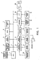
- Fig. 1 shows a block diagram of a video game device which may achieve the invention.
- the video game device is the same as a device disclosed in JP 8235366 of 13.09.96 .
- the video game device implementing the invention includes a body and elements which are connected to the body.
- the elements include a television monitor 10, speaker 13, memory card 19, a controller 20.
- the configuration of the video game device is an example for a game device for family use.
- the body further includes a CPU 1, a bus 2 which is connected to the CPU 1, and constituents which are connected to the bus 2.
- the bus 2 is configured of an address bus, a data bus, and a control bus. And a graphics data generating processor 3, a peripheral device controller 4, a main memory 5, a ROM 6, an expansion circuit 7, a graphic processor 8, a frame buffer 9, a sound processor 11, a sound buffer 12, a decoder 14, a buffer 15, a storage medium drive 16, and an interface circuit 18 are connected to the bus 2.
- the television monitor 10 (hereinafter, is simply referred to as “monitor") is connected to the graphic processor 8, the speaker 13 is connected to the sound processor 11, and the memory card 19 and the controller 20 are connected to the interface circuit 18.
- the storage medium 17 stores a program and data which are required to execute a game.
- the contents of the program and the data are supplied via the storage medium drive 16 to the game device.
- the storage medium includes, for example, a portable storage medium, such as a od-rom and an optical disk.
- the monitor 10 may be a monitor of a domestic television
- the speaker 13 may be a speaker of the domestic television.
- Fig. 1 In the case where an arcade game device implements the method of the invention, the elements shown in Fig. 1 may be incorporated to one package.
- the monitor 10 may be a CRT display connected to the computer, and the controller 20 may be an input device, such as a keyboard or mouse of the computer.
- the CPU 1 depicted is, for example, a 32-bit RISC (reduced instruction set computer) CPU, which controls the whole device by executing the operating system stored in the ROM 6.
- RISC reduced instruction set computer
- the graphics data generating processor 3 serves as a co-processor of the CPU 1. That is, the graphics data generating processor 3 performs co-ordinates conversion and light source calculating (for example, calculation of matrix including fixed point elements and vector operation) in parallel in order to display a pseudo 3D image.
- the peripheral, device controller 4 performs interrupt control, time control, memory control, and control for direct access memory (DMA) transfer.
- DMA direct access memory
- the Rom 6 stores the operating system which controls operation on each element.
- the expansion circuit 7 decodes still or animated image data read out from the storage medium 17 and stored in the main memory 5, under the control of the aforementioned CPU 1, and stores the decoded image data back in the main memory 5.
- the expansion circuit 7 is capable of high-speed execution of inverse discrete cosine transform (inverse DCT) operations, and it is also capable of expending compressed data read out from the storage medium 17 in accordance with still color image compression standards (known as JPEG) or cumulative media moving image encoding standards (known as MPEG).
- JPEG still color image compression standards
- MPEG cumulative media moving image encoding standards
- the graphic processor 8 renders polygon images and stores them into the frame buffer 9 in response to instructions from the CPU 1.
- the frame buffer 9 includes display area and non-display area.
- the display area is an area in which images corresponding to a display area on the monitor 10 are stored.
- the non-display area is an area in which animation images used to produce 2D images in the display area and textures used to produce pseudo 3D images are stored.
- the frame buffer 9 includes a color lookup table (CLUT) which corresponds a color of pixel to a number. Also, data in the display area in the frame buffer 9 are transferred to the monitor 10 at high-speed.
- the frame buffer 9 consists of a so-called dual-port RAM, and it is capable of simultaneously receiving images from the graphics data generating processor 3 (CPU 1) or transferring data from the main memory 5, and reading out data in order that the data can be displayed to the monitor 10.
- the sound processor 11 outputs music or an effective sound via speaker 13 by regenerating ADPCM data in the storage medium 17 or voice data stored in the sound buffer 12, or by modulating and regenerating the voice data.
- the decoder 14 decodes a program or data which are stored in the storage medium 17 and are appended an error checking and correction (ECC) code, and provides the program or the data to the main memory 5 or the sound processor 11.
- ECC error checking and correction
- the buffer 15 temporarily stores the program and/or data regenerated from the storage medium 17.
- the buffer 15 is, for example, 32 kilobytes of buffer.
- the storage medium drive 16 may be cd-rom drive, optical disk drive and the like.
- the storage medium drive 16 reads out a program and another data from the storage medium 17, and provides them to the decoder 14.
- the interface circuit 20 sends an operation signal received from the controller 20 to the CPU 1. Also, the interface circuit 20 reads out the contents of the memory card 19 to supply the contents to the main memory 5, simultaneously that, stores data into the memory card 19 in response to an instruction of the CPU 1.
- the memory card 19 stores values of a various of parameters in order to, for example, maintain the status at the time point when a game terminates last time.
- a card type memory is used as the memory card 19, but many types of memories may be used.
- the controller 20 is used to play a game by a user.
- the controller 20 includes direction buttons for moving a character on the monitor upwards, downwards, leftwards and rightwards, and a plurality of function buttons for instructing one of specific functions, for example, starting the game or selecting items.
- the frame buffer 9 includes a capacity of a height of 512 pixels by a width of 1024 pixels and there is two bytes (sixteen bits) of information for each pixel. Therefore, whole capacity of the frame buffer 9 is 1,048,576 bytes (512 x 1024 x 2 bytes), that is one megabytes.
- the pixels along the width may be called zero-th through 1023-th pixels (0 to 1023) while the pixels along the height may be called zero-th through 511-th pixels (0 to 511).
- pixels ranged between 0-399 in height and between 0-319 in width are assigned to a display area 41 depicted in Fig. 2 and the other pixels in the other range are assigned to a non-display area.
- the size of the display area 41 may vary for each game or scene of the game based on resolution of the game.
- the display area 41 includes a height of 400 pixels by a width of 320 pixels, but when images are required to display on the monitor 10 at higher resolution, larger size of the display area, such as an area of a height of 400 pixels by a width of 512 pixels, is required. Therefore, when different images are displayed to the same size on the monitor 10, one image having a height of 400 pixels by a width of 512 pixels is displayed at higher resolution than the resolution of the other image having a height of 400 pixels by a width of 320 pixels. This is because the former image has larger number of pixels in the same display area. Also, when the capacity of the display area 41 is increased, the capacity of the non-display area is reduced and the size or the number of patterns of images stored in the non-display area are limited, since the frame buffer 9 has the fixed capacity (herein, one megabytes).
- the non-display area of the frame buffer 9 includes a non-display area for pseudo 3D images 42 and a non-display area for 2D images 43.
- the non-display area for pseudo 3D images 42 resides in an area which is ranged between 0-319 in width and between 400-511 in height, is assigned to store data which are used to produce the pseudo 3D images, that is texture.
- the non-display area for 2D images 43 resides in an area other than the display area 41 and the non-display area for pseudo 3D images 42, and is assigned to store data which are used to produce the 2D images, that is animation images etc.
- the non-display area for 2D images 43 is divided into several sections based on categories of an object to be displayed to simplify management of the images.
- the size of the non-display area for pseudo 3D images 42, the size of the non-display area for 2D images 43, and the sections in the non-display area for 2D images 43 may vary for each game or scene of the game, as similar to the display area 41.
- the frame buffer 9 shown in Fig. 2 may be used, for example, in the following game.
- a user of the game selects two characters among three characters (character 1 to 3) and controls them to perform a various of operations, for example, to combat with enemy characters using the controller 20. Movements of the characters are displayed using pseudo 3D images. Under a certain condition, the upper part of two or three characters are displayed using 2D images and the user has a conversation with the characters in the game. In this point, the pseudo 3D images are displayed as background of the 2D images. In some case, the 2D images are displayed as background. The 3D images displayed as background may be continuously changed based on a predetermined routine simultaneously with change of the 2D animation images.
- Fig. 3 shows the actual data in the frame buffer 9 stored along with the layout of the frame buffer shown in Fig. 2. However, representation is omitted about the actual data in a right part of the frame buffer shown in Fig. 3.
- the frame buffer 9 is divided sections each of which has the size of 64 pixels wide x 256 pixels height. However, these sections are defined in order to simplify management and ease understanding. Furthermore, an area which is ranged between 0-319 in width and between 0-399 in height is a display area 51 which corresponds to the display area 41 shown in Fig. 2. In Fig. 3, no data are shown in the display area 51, but when the user play the game, images to be displayed on the monitor 10 are repeatedly produced in the display area 51 at high-speed, such as 10 frames per second to 60 frames per second.
- a color of each pixel may be represented by relating the pixel to a color identification number which is defined by the CLUT.
- each pixel itself has color information (for example, a set of values of RGB) and the pixel is colored by the color information. Therefore, an image defined as the display area 51 is directly displayed on the monitor 10 connected to the video game device.
- a texture 52 is stored in a location corresponding to the display area for pseudo 3D images 42 shown in Fig. 2.
- the texture 52 includes a dozens of expression patterns of enemy character's eye. In a game, one of the expression pattern is selected according to a status of an enemy character and the selected pattern is put on a polygon in a location corresponding to the enemy character's eye.
- Images required to represent a character 1 as 2D image are stored in a location corresponding to the area to be stored to represent the upper part of character 1 in the non-display area for 2D images shown in Fig. 2.
- the images in the area include a plurality of stripped images and it is not clear what the images subsequently represent. However, when a part of images are selected and combined based on instructions from the CPU 1, groundwork for an image of the upper part of character 1 is produced in the display area 41.
- each of the stripped images may be stored in an orientation (for example, lengthwise or breadthwise) different from that of the image to be displayed.
- the image when a rectangular image (representing an eye and including a width of 20 pixels by height of 10 pixels) is put on a location in the display area 51, the image is generally stored in the non-display area for 2D images 43 in the same orientation as the image to be displayed in the area 51. However, there may be no space in the area 51 to store the rectangular image in the original orientation.
- the rectangular image when the area includes an empty space defined a width of 10 pixels by a height of 20 pixels, the rectangular image may be stored in the area 51 as an image having a width of 10 pixels by a height of 20 pixels by rotating the image clockwise (or counterclockwise) by an angle of 90 degrees. The image is rotated back counterclock-wise (or clockwise) by an angle of 90 degrees when the image is put on the display area 51.
- the area corresponding to the area of the upper part of character 1 shown in Fig. 2 further includes changed images which are used to display a part of the character 1 which changes.
- the changing parts of the character 1 in the display area 51 is replaced with the corresponding changed images and displayed on the monitor 10.
- another changed image is put on a part of the character 1 in the display area 51 and displayed on the monitor 10.
- the unit may be reduce to a pixel, then efficiency of usage of the frame buffer become the best in that unchanged data is not stored redundantly.
- the unit is small, the number of putting images on the display area 51 tends to be increased, as a result, load of the CPU 1 is increased.
- the size of the image to be prepared should be determined by comparing the merit that the frame buffer 9 is used effectively with the demerit described above. Also, the size of the image is not always fixed for all the images.
- the stripped image data is illustrated in connection with display of 2D image, however, the stripped image data may also be applied to the textures 52 which are used to display the pseudo 3D image.
- the capacity of image data which are used to display the pseudo 3D images is extremely saved in addition to the reduction of the required capacity of the frame buffer.
- the capacity of textures which are mapped to polygons becomes huge, however in the invention, the textures are mapped to only polygons in a part of a face (for example, a part of the face such as eye) of a main character and mapping to the other polygons is avoided.
- the frame buffer 9 shown in Fig. 3 is merely illustrated. Indeed, all the areas in the frame buffer 9 are filled with images except for the display area 51. Further, images shown in the frame buffer 9 are displayed with a vertical length which is longer than a vertical length actually displayed on the monitor 10, but this is not essential since difference of an aspect ratio for arrangement of pixels.
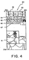
- Fig. 4 shows an enlarged area 60 corresponding to the area which is shown in Fig. 3 and ranged between 320-383 in width and between 0-255 in height.
- This area 60 stores images which may represent motion (change) of a character for a certain period in a game. Therefore, there are a plurality of images for the same part of the character.
- the area 60 stores images corresponding to a part of the character such as eyes (62-65) and months (66, 67) in the upper section.
- the area 60 further stores images corresponding to an outline of the character such as the whole upper part (61) and a body.
- images corresponding to eyes (62-65) the images which resides in the first and second rows including images 62 and 63 are used to represent a plurality patterns of left eyes of the character (right side of the character as you face him/her).
- the images which resides in the third and fourth rows including images 64 and 65 are used to represent a plurality patterns of right eyes of the character (left side of the character as you face him/her).
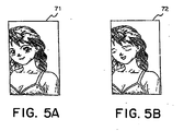
- Figs. 5A and 5B show images which are produced using the images in the area 60 shown in Fig. 4.
- Fig 5A shows image 71 displayed at a time point.
- Fig. 5B shows image 72 displayed at a frame next or after a several frames later from the image 71.
- the image 61 in the area 60 shown in Fig. 4 and an image represent the upper part of head are concatenated to produce an image of the upper part of the character, and the concatenated image is stored into the display area of the frame buffer 9.
- areas corresponding to eyes and mouth are empty.
- the image 62 in the area 60 is put on an area corresponding to a left eye of the character and the image 64 in the area 60 is put on an area corresponding to a right eye.
- image 66 in the area 60 is put on the area corresponding to the mouth.
- the image 71 is produced to represent a usual expression.
- the image 72 shown in Fig. 5B is produced by overlapping the changed images on the image 71.
- the image 63 in the area 60 shown in Fig. 4 is overlapped on the area corresponding to the left eye and the image 65 is overlapped on the area corresponding to the right eye.
- the image 67 in the area 60 is overlapped on the area corresponding to the mouth to produce the image 72 which represents the expression of the character who closes eyes and start talking.
- the desirable size of the area depends on characteristic of game images which transit for a period of time. Therefore, the size of the area is manually determined after trial and error. However, if a series of game images may be all read as data, using a computer, the following process may be performed. The process causes a load of developer of a game to reduce remarkably
- the process executes the steps of focusing a series of movement of a character, selecting a plurality of images representing the movement of the character, accumulating parts which occur at least one change among the selected images, defining a plurality of rectangular areas so that the parts may be all covered.
- the rectangular area is divided into a plurality of smaller size of rectangular areas.
- the process further executes steps of accumulating parts which occur at least one change in the divided rectangular area, and defining the smallest rectangular area so that the parts may be all covered.
- the accumulating step and the defining step are repeated until size of the each defined area are reduced to be desirable.
- images representing the changing part are prepared in a unit of the defined desirable size of rectangular area.
- images representing eye or mouth are defined in a unit of the size covering the eye or the mouth. The images then transferred to the frame buffer 9.
- the desirable size depends on the power of expression of the game, or a period which a game should continue displaying images without replacing the frame buffer
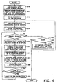
- Fig. 6 shows a flowchart of the steps.
- the process is started when the storage medium 17 is set to the video game device which has been powered on, or when the video game device is powered on with the storage medium 17 in the video game device.
- the storage medium drive 16 reads out images, voice, and program data from the storage medium 17 in step S10.
- the decoder 14 performs ECC operation on the read data and stores the data into the main memory 5. But, the voice data may be directly transferred to the sound processor 11 as required and then the voice data are stored into the sound buffer 12 in step S11.
- step S12 the program data stored in the main memory 5 are started as game program.
- the expansion circuit 7 performs expansion operation on the image data stored in the main memory 5 based on its compressed format, and stores back the data into the main memory 5 in step S13.
- step S14 image data which are used to produce 2D images and pseudo 3D images required for a predetermined period time (i : a period in the game) are transferred from the storage medium 17 or the main memory 5 to the non-display area in the frame buffer 9. At this point, a plurality of image data are stored in predetermined locations in the frame buffer 9 as shown in Fig. 3.
- the predetermined period time i is not the fixed period, for example five or twenty minutes, but a predetermined game period which the game may continue displaying images on the monitor 10 using only once stored image in the frame buffer 9. Therefore, when a various of scenes and a plurality of colorful images are frequently used, the predetermined period time becomes comparatively short since the number of patterns of image to be used becomes large.
- the predetermined period time becomes comparatively long since only using images in the non-display area, display of the image on the monitor 10 continues for a long time.
- the predetermined period time is extended in the two cases since each changing part of the image is stored as a small area of image data into the frame buffer 9.
- step S15 it is determined whether or not images to be displayed next frame belongs to the current predetermined period time based on the scenario of the game or user's instructions. If the images belongs(step S15(Y)), process proceeds to step S16.
- step S16 required calculations about the pseudo 3D image are performed by the CPU 1.
- the CPU 1 determines coordinates (polygon vertex coordinates) of each vertex of each polygon in the 3D space to be displayed, and address data (in the non-display area in the frame buffer 9) of textures put on each polygon.
- the CPU 1 determines address data in the non-display area of the frame buffer 9 in which image data corresponds to the changed part are stored to replace only the changed part.
- step S17 each of the polygon vertex coordinates in the 3D space determined in step S16 is supplied to the graphics processor 3, and then the polygon vertex address data and brightness of the corresponding texture etc. are determined so that that the polygon vertex coordinates in the 3D space may be represented to the monitor in 2D space.
- step S18 a required calculation for displaying the 2D image is performed by the CPU 1.
- the CPU 1 determines the first address data in the display area of the frame buffer 9 and second address data in the non-display area of the frame buffer 9.
- the first and the second address data are of animation images prepared to display image.
- address data of the corresponding new image in the non-display area are determined in order to replace the changed area with the corresponding new image.
- step S19 required data, which are obtained from steps S16 to S18, about the pseudo 3D images and the 2D images is supplied to the graphic processor 8. Then, the graphic processor 8 produces a game image to be displayed on the monitor 10 from the supplied data and stores them into the display area of the frame buffer 9.
- the graphic processor 8 produces a game image to be displayed on the monitor 10 from the supplied data and stores them into the display area of the frame buffer 9.
- each of the textures in the non-display area is put on the corresponding polygon to produce the pseudo 3D images, and then the animation images in the non-display area are overlapped on the pseudo 3D images.
- step S20 when producing of the game image in the display area is completed, the contents of the game image are transferred to the monitor 10 at high-speed.
- step S21 it is determined whether or not there is an instruction (for example, to display a menu or to move an object) from a user via the controller 20 and the interface circuit 18.
- step S21(N) When there is no instruction (step S21(N)), process goes back to step S15.
- step S21(Y) process proceeds step S22, analyzes the instruction, and goes back to step S15. The instruction is evaluated in step S15 and processing corresponding to the instruction is performed.
- Processing in the loops between steps S15 and S21, and steps S15 and S 22 is performed at high-speed in a game displaying moving images to the monitor 10.
- the processing is repeated 10-60 times per second (that is, 10-60 frames per second (fps)).
- step S15 when it is determined that the current scene does not belong to the period i no longer (step S15(N)), process goes to step S23 and determines whether the game ends or not. When it is determined that the game ends (step S23(Y)), the process terminates. The game is ended by a various of events such as user's instruction (for example, suspend instruction and terminate instruction).
- step S24 When it is determined that the game is still continued (step S23(N)), process goes to step S24. This is when a scene of the game is drastically or dramatically changed, as a result, replacing of contents in the non-display area of the frame buffer 9 occurs. Therefore, in step S24, the period is set to the period i + 1 which is next to the period i, image data required in the period i + 1 are read out from the storage medium 17 or from the main memory 5. Then, process return to step S13, wherein expansion process are performed on the image data from the storage medium 17. Then, in step S14, the image data are stored into the non-display area of the frame buffer 9.
- a video game device may use a plurality of frame buffers, but even in this case, according to the invention, the non-display area in the frame buffers may be used efficiently.
- Fig. 7 shows an image displayed on the monitor 10 at one time point.
- Fig. 8 shows another image displayed on the monitor 10 at another time point.
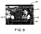
- Fig. 9 shows still another image displayed on the monitor 10 as a frame next to the image shown in Fig. 8.
- the image 100 shown in Fig. 7 represents combat scene in a town 101, and wherein, two characters (102, 103) shoot at an enemy character 104 based on instructions of user via the controller 20.
- two characters drive the enemy character into the depth of the town based on the instructions of user
- a viewpoint of the game moves to the depth of the town according to the movement of the characters because the image 100 is represented using the pseudo 3D images.
- the image 120 shown in Fig. 8 represents two characters (122, 123) displayed using the 2D animation images with a background representing a town and displayed using the pseudo 3D images. Furthermore, in the lower part of the image 120, an area 124 is located and a talk of the characters (122, 123) is represented as letters in the area 124.
- the image 120 shows a scene when the two characters (102, 103) shown in Fig. 7 need to have a conversation in combating. To represent this situation, the upper part of the characters are shown on the image 100 shown in Fig. 7 in close-up style.
- the character 122 shown in Fig. 8 corresponds to the character 102 shown in Fig. 7.
- the character 123 shown in Fig. 8 corresponds to the character 103 shown in Fig. 7.
- the characters (102, 103) are shown in small size as fitted into the background in Fig. 7, but when a condition is satisfied, the characters are shown in more detail as 2D images of enlarged upper part of the characters.
- the image 140 shown in Fig. 9 shows two characters (142, 143) which are displayed using the 2D animation images and who are substantially the same as characters shown in Fig. 8 with background which is displayed using the pseudo 3D image and represents the town as similar to the town shown in Fig. 8. Further, the image 140 includes an area 144 as similar to the area 124 in the lower part, and a talk of the characters (142, 143) is displayed in the area 144.
- the character 142, 143 in Fig. 9 are different from the corresponding characters 122, 123 in Fig. 8 in that the size of the opening mouth and the opening eyes, and the form of hair are different from each other.
- the images shown in Fig. 8 and Fig. 9 represent only two scenes which are very close in time. However, when such a change between the images is supplied over a great number of frames, the characters etc. are added to expression of natural motion.
- expression of talking characters is realized by changing the size of opening mouth one after another.
- expression of flowing hair in the wind is realized by changing the form of hair in order.
- the transitional change is performed by replacing only the changed part of the image (for example, only mouth part or only front hair part) in the display area of the frame buffer 9 with the corresponding new area.
- the 2D images and the pseudo 3D images may be displayed simultaneously on the display device.
Claims (7)
- Dispositif de jeu vidéo pour une utilisation dans l'affichage d'une image de jeu composé d'une combinaison d'une représentation tridimensionnelle avec une représentation bidimensionnelle sur un dispositif d'affichage (10), caractérisé par :une mémoire d'image (9) qui comprend une première zone (41) stockant une première image qui doit être affichée sur le dispositif d'affichage (10) et une seconde zone (42, 43) pour stocker des secondes images optimisées en taille, emplacement, et orientation et qui sont sous-divisées dans une taille prédéterminée comme des images partielles ;un dispositif de production d'image de jeu qui produit une première image remplacée sur la base des opérations du jeu en remplaçant les parties de la première image qui changent en fonction des opérations du jeu par les secondes images qui correspondent aux parties changeantes de la première image ; etun dispositif de stockage d'image de jeu qui stocke la première image remplacée dans la première zone (41);le dispositif d'affichage d'image de jeu affiche, comme l'image de jeu, la première image remplacée qui est produite par le dispositif de production d'image de jeu et qui est stockée par le dispositif de stockage d'image de jeu dans la première zone (41), sur le dispositif d'affichage (10).
- Dispositif de jeu vidéo selon la revendication 1, dans lequel chacune des secondes images est une image partielle d'une taille prédéterminée, et stockée dans un emplacement prédéterminé dans la seconde zone (42, 43) en considération de l'orientation relative entre une image qui doit être stockée dans la seconde zone (42, 43) et l'image qui doit être affichée, et dans lequel les secondes images comprennent les images représentant les changements selon un passage de temps dans une partie de la première image et ainsi le nombre de fois pour accéder à la mémoire d'image (9) est réduit en remplaçant les parties de la première image par les secondes images l'une après l'autre.
- Dispositif de jeu vidéo selon la revendication 1 ou 2, dans lequel ladite pluralité de polygones change les emplacements de ses sommets selon un passage de temps.
- Dispositif de jeu vidéo selon la revendication 2 ou 3, comprenant en outre :un première dispositif définissant une région qui sélectionne une pluralité d'images représentant le mouvement d'un personnage, accumule les parties changées ce qui produit au moins un changement parmi les images sélectionnées, et définit une quelconque forme des premières régions de sorte que les parties sont toutes couvertes, pour représenter une série de mouvements du personnage ;un dispositif divisant une région qui divise la première région en une pluralité de secondes régions, si la taille de la première région est supérieure à une taille prédéterminée ;un deuxième dispositif définissant une région qui accumule les parties entre les deuxièmes régions affichant la même partie de la première image à laquelle au moins un changement se produit et qui définit une quelconque forme des troisièmes régions de sorte que les parties sont toutes couvertes ;un dispositif commandant une division de région qui commande le dispositif divisant une région et le dispositif définissant une deuxième région pour répéter la division et la définition jusqu'à ce que les tailles des troisièmes régions soient dans une taille prédéterminée ou jusqu'à ce que le nombre de fois de la division soit un nombre prédéterminé ; etun dispositif stockant une image qui stocke les parties de changement comme les secondes images dans une unité de la taille résultante des troisièmes régions.
- Dispositif de jeu vidéo selon la revendication 4, dans lequel une quelconque forme est rectangulaire.
- Procédé d'affichage d'une première image comme une image de jeu, le procédé comprenant les étapes consistant à :diviser une mémoire d'image (9) dans une première zone (41) stockant la première image et dans une seconde zone (42, 43) stockant les secondes images ;optimiser la taille, l'emplacement, et l'orientation de chacune des secondes images qui doivent être stockées dans la seconde zone (42, 43) ;stocker les secondes images qui sont utilisées pour produire la première image et qui sont sous-divisées dans une taille prédéterminée comme des images partielles dans la seconde zone (42, 43) ;remplacer les parties de la première image qui changent en fonction des opérations du jeu par les secondes images qui correspondent aux parties changeantes de la première image ; etstocker et afficher la première image remplacée.
- Support lisible par ordinateur qui stocke un programme servant à afficher une image de jeu sur un dispositif d'affichage (10), le programme comprend les étapes consistant à :diviser une mémoire d'image (9) dans une première zone (41) stockant la première image et dans une seconde zone (42, 43) stockant les secondes images ;optimiser la taille, l'emplacement, et l'orientation de chacune des secondes images qui doivent être stockées dans la seconde zone (42, 43) ;stocker les secondes images qui sont utilisées pour produire la première image et qui sont sous-divisées dans une taille prédéterminée comme des images partielles dans la seconde zone (42, 43) ;remplacer les parties de la première image qui changent en fonction des opérations du jeu par les secondes images qui correspondent aux parties changeantes de la première image ; etstocker et afficher la première image remplacée.
Applications Claiming Priority (2)
| Application Number | Priority Date | Filing Date | Title |
|---|---|---|---|
| JP28713198 | 1998-10-08 | ||
| JP10287131A JP2000107447A (ja) | 1998-10-08 | 1998-10-08 | ビデオゲーム装置、ゲーム画像表示方法、及び記録媒体 |
Publications (3)
| Publication Number | Publication Date |
|---|---|
| EP1003130A2 EP1003130A2 (fr) | 2000-05-24 |
| EP1003130A3 EP1003130A3 (fr) | 2003-04-02 |
| EP1003130B1 true EP1003130B1 (fr) | 2007-06-20 |
Family
ID=17713476
Family Applications (1)
| Application Number | Title | Priority Date | Filing Date |
|---|---|---|---|
| EP99119906A Expired - Lifetime EP1003130B1 (fr) | 1998-10-08 | 1999-10-08 | Dispositif de jeu vidéo |
Country Status (4)
| Country | Link |
|---|---|
| US (1) | US6468161B1 (fr) |
| EP (1) | EP1003130B1 (fr) |
| JP (1) | JP2000107447A (fr) |
| DE (1) | DE69936332T2 (fr) |
Families Citing this family (28)
| Publication number | Priority date | Publication date | Assignee | Title |
|---|---|---|---|---|
| JP4519290B2 (ja) * | 2000-08-04 | 2010-08-04 | 株式会社バンダイナムコゲームス | ゲーム装置、画像生成方法、及び記録媒体 |
| TW476919B (en) * | 2000-11-09 | 2002-02-21 | Cyberlink Corp | 2.5 dimensional head image rendering method |
| US6657621B2 (en) * | 2001-05-01 | 2003-12-02 | Hewlett-Packard Development Company, L.P. | Device and method for scrolling stored images across a display |
| JP3559011B2 (ja) * | 2001-10-02 | 2004-08-25 | コナミ株式会社 | ゲーム装置、ゲーム制御方法およびプログラム |
| US20040075623A1 (en) * | 2002-10-17 | 2004-04-22 | Microsoft Corporation | Method and system for displaying images on multiple monitors |
| US8968093B2 (en) * | 2004-07-15 | 2015-03-03 | Intel Corporation | Dynamic insertion of personalized content in online game scenes |
| JP3814661B2 (ja) * | 2004-07-30 | 2006-08-30 | 株式会社コナミデジタルエンタテインメント | ゲームプログラム及びゲーム装置 |
| JP2006061198A (ja) * | 2004-08-24 | 2006-03-09 | Samii Kk | 画像処理装置、画像処理方法及びプログラム |
| JP3880603B2 (ja) * | 2005-02-22 | 2007-02-14 | 株式会社コナミデジタルエンタテインメント | 画像処理装置、画像処理方法及びプログラム |
| US20070060346A1 (en) * | 2005-06-28 | 2007-03-15 | Samsung Electronics Co., Ltd. | Tool for video gaming system and method |
| KR100657322B1 (ko) * | 2005-07-02 | 2006-12-14 | 삼성전자주식회사 | 로컬 3차원 비디오를 구현하기 위한 인코딩/디코딩 방법 및장치 |
| US7459624B2 (en) | 2006-03-29 | 2008-12-02 | Harmonix Music Systems, Inc. | Game controller simulating a musical instrument |
| JP4227639B2 (ja) * | 2006-10-26 | 2009-02-18 | 株式会社テンヨー | 手品補助玩具 |
| US8808087B2 (en) * | 2007-02-22 | 2014-08-19 | Sony Corporation | Game device, game control method, and game control program |
| US8690670B2 (en) | 2007-06-14 | 2014-04-08 | Harmonix Music Systems, Inc. | Systems and methods for simulating a rock band experience |
| US8678896B2 (en) | 2007-06-14 | 2014-03-25 | Harmonix Music Systems, Inc. | Systems and methods for asynchronous band interaction in a rhythm action game |
| US8663013B2 (en) | 2008-07-08 | 2014-03-04 | Harmonix Music Systems, Inc. | Systems and methods for simulating a rock band experience |
| US8564555B2 (en) * | 2009-04-30 | 2013-10-22 | Synaptics Incorporated | Operating a touch screen control system according to a plurality of rule sets |
| US8465366B2 (en) | 2009-05-29 | 2013-06-18 | Harmonix Music Systems, Inc. | Biasing a musical performance input to a part |
| US8449360B2 (en) | 2009-05-29 | 2013-05-28 | Harmonix Music Systems, Inc. | Displaying song lyrics and vocal cues |
| EP2494432B1 (fr) | 2009-10-27 | 2019-05-29 | Harmonix Music Systems, Inc. | Interface gestuelle |
| US9981193B2 (en) | 2009-10-27 | 2018-05-29 | Harmonix Music Systems, Inc. | Movement based recognition and evaluation |
| US8550908B2 (en) | 2010-03-16 | 2013-10-08 | Harmonix Music Systems, Inc. | Simulating musical instruments |
| US8562403B2 (en) | 2010-06-11 | 2013-10-22 | Harmonix Music Systems, Inc. | Prompting a player of a dance game |
| US9358456B1 (en) | 2010-06-11 | 2016-06-07 | Harmonix Music Systems, Inc. | Dance competition game |
| US20110306397A1 (en) | 2010-06-11 | 2011-12-15 | Harmonix Music Systems, Inc. | Audio and animation blending |
| US9024166B2 (en) | 2010-09-09 | 2015-05-05 | Harmonix Music Systems, Inc. | Preventing subtractive track separation |
| EP2728551B1 (fr) * | 2012-11-05 | 2019-07-17 | Rightware Oy | Procédé et système de rendu d'image |
Family Cites Families (6)
| Publication number | Priority date | Publication date | Assignee | Title |
|---|---|---|---|---|
| US4961153A (en) * | 1987-08-18 | 1990-10-02 | Hewlett Packard Company | Graphics frame buffer with strip Z buffering and programmable Z buffer location |
| US5830065A (en) * | 1992-05-22 | 1998-11-03 | Sitrick; David H. | User image integration into audiovisual presentation system and methodology |
| US5561745A (en) * | 1992-10-16 | 1996-10-01 | Evans & Sutherland Computer Corp. | Computer graphics for animation by time-sequenced textures |
| CN1130664C (zh) * | 1993-05-21 | 2003-12-10 | 世嘉企业股份有限公司 | 图象处理装置及方法 |
| JP3547236B2 (ja) | 1994-12-02 | 2004-07-28 | 株式会社ソニー・コンピュータエンタテインメント | 画像情報生成装置及び方法、並びに画像情報処理装置及び方法 |
| GB9610212D0 (en) * | 1996-05-16 | 1996-07-24 | Cyberglass Limited | Method and apparatus for generating moving characters |
-
1998
- 1998-10-08 JP JP10287131A patent/JP2000107447A/ja active Pending
-
1999
- 1999-10-08 US US09/414,523 patent/US6468161B1/en not_active Expired - Lifetime
- 1999-10-08 DE DE69936332T patent/DE69936332T2/de not_active Expired - Lifetime
- 1999-10-08 EP EP99119906A patent/EP1003130B1/fr not_active Expired - Lifetime
Non-Patent Citations (1)
| Title |
|---|
| None * |
Also Published As
| Publication number | Publication date |
|---|---|
| DE69936332T2 (de) | 2007-12-06 |
| JP2000107447A (ja) | 2000-04-18 |
| EP1003130A3 (fr) | 2003-04-02 |
| EP1003130A2 (fr) | 2000-05-24 |
| US6468161B1 (en) | 2002-10-22 |
| DE69936332D1 (de) | 2007-08-02 |
Similar Documents
| Publication | Publication Date | Title |
|---|---|---|
| EP1003130B1 (fr) | Dispositif de jeu vidéo | |
| JP3133299B2 (ja) | ゲーム装置、動画像表示方法及び記録媒体 | |
| JP3270928B2 (ja) | フィールドマップ生成方法、ビデオゲームシステム、及び記録媒体 | |
| JP2010022646A (ja) | プログラム、情報記憶媒体および画像生成システム | |
| JP2000132706A (ja) | 記録媒体、画像処理装置および画像処理方法 | |
| JP4804122B2 (ja) | プログラム、テクスチャデータ構造、情報記憶媒体及び画像生成システム | |
| JP3777288B2 (ja) | ゲームシステム及び情報記憶媒体 | |
| JP3449993B2 (ja) | 画像生成システム、プログラム及び情報記憶媒体 | |
| JP2003323630A (ja) | 画像生成システム、プログラム及び情報記憶媒体 | |
| JP2002063596A (ja) | ゲームシステム、プログラム及び情報記憶媒体 | |
| JP2002092628A (ja) | ゲームシステム、情報記憶媒体及び圧縮データの生成方法 | |
| JP2009129167A (ja) | プログラム、情報記憶媒体、及び画像生成システム | |
| US6972766B2 (en) | Recording medium storing dynamic picture image generation program, dynamic picture image generation program, dynamic picture image generation method, and device for the same | |
| JP3467259B2 (ja) | ゲームシステム、プログラム及び情報記憶媒体 | |
| JP4656617B2 (ja) | ゲームシステム、プログラム及び情報記憶媒体 | |
| JP3297410B2 (ja) | 画像生成システム及び情報記憶媒体 | |
| JP4632855B2 (ja) | プログラム、情報記憶媒体及び画像生成システム | |
| JP4913898B2 (ja) | ゲームシステム、プログラム及び情報記憶媒体 | |
| JP3292713B2 (ja) | 画像生成システム及び情報記憶媒体 | |
| JP3872032B2 (ja) | 画像生成プログラム、画像生成装置、画像生成方法及びビデオゲーム装置 | |
| JP4394211B2 (ja) | 画像生成システム及び情報記憶媒体 | |
| JP2002541600A (ja) | 透視変換する装置及び方法 | |
| JP2002063591A (ja) | ゲームシステム、プログラム及び情報記憶媒体 | |
| JP4391633B2 (ja) | 画像生成システム及び情報記憶媒体 | |
| JP3326128B2 (ja) | ゲーム装置、画像表示方法、及び、プログラムを記録した機械読み取り可能な情報記録媒体 |
Legal Events
| Date | Code | Title | Description |
|---|---|---|---|
| PUAI | Public reference made under article 153(3) epc to a published international application that has entered the european phase |
Free format text: ORIGINAL CODE: 0009012 |
|
| AK | Designated contracting states |
Kind code of ref document: A2 Designated state(s): AT BE CH CY DE DK ES FI FR GB GR IE IT LI LU MC NL PT SE |
|
| AX | Request for extension of the european patent |
Free format text: AL;LT;LV;MK;RO;SI |
|
| PUAL | Search report despatched |
Free format text: ORIGINAL CODE: 0009013 |
|
| AK | Designated contracting states |
Kind code of ref document: A3 Designated state(s): AT BE CH CY DE DK ES FI FR GB GR IE IT LI LU MC NL PT SE Designated state(s): AT BE CH CY DE DK ES FI FR GB GR IE IT LI LU MC NL PT SE |
|
| AX | Request for extension of the european patent |
Extension state: AL LT LV MK RO SI |
|
| RIC1 | Information provided on ipc code assigned before grant |
Ipc: 7G 06T 1/60 B Ipc: 7G 06T 15/70 A |
|
| 17P | Request for examination filed |
Effective date: 20030904 |
|
| AKX | Designation fees paid |
Designated state(s): DE FR GB |
|
| 17Q | First examination report despatched |
Effective date: 20050117 |
|
| GRAP | Despatch of communication of intention to grant a patent |
Free format text: ORIGINAL CODE: EPIDOSNIGR1 |
|
| GRAS | Grant fee paid |
Free format text: ORIGINAL CODE: EPIDOSNIGR3 |
|
| GRAA | (expected) grant |
Free format text: ORIGINAL CODE: 0009210 |
|
| AK | Designated contracting states |
Kind code of ref document: B1 Designated state(s): DE FR GB |
|
| REG | Reference to a national code |
Ref country code: GB Ref legal event code: FG4D |
|
| REF | Corresponds to: |
Ref document number: 69936332 Country of ref document: DE Date of ref document: 20070802 Kind code of ref document: P |
|
| ET | Fr: translation filed | ||
| PLBE | No opposition filed within time limit |
Free format text: ORIGINAL CODE: 0009261 |
|
| STAA | Information on the status of an ep patent application or granted ep patent |
Free format text: STATUS: NO OPPOSITION FILED WITHIN TIME LIMIT |
|
| 26N | No opposition filed |
Effective date: 20080325 |
|
| PGFP | Annual fee paid to national office [announced via postgrant information from national office to epo] |
Ref country code: FR Payment date: 20121031 Year of fee payment: 14 Ref country code: DE Payment date: 20121023 Year of fee payment: 14 |
|
| PGFP | Annual fee paid to national office [announced via postgrant information from national office to epo] |
Ref country code: GB Payment date: 20121019 Year of fee payment: 14 |
|
| REG | Reference to a national code |
Ref country code: DE Ref legal event code: R119 Ref document number: 69936332 Country of ref document: DE |
|
| GBPC | Gb: european patent ceased through non-payment of renewal fee |
Effective date: 20131008 |
|
| PG25 | Lapsed in a contracting state [announced via postgrant information from national office to epo] |
Ref country code: GB Free format text: LAPSE BECAUSE OF NON-PAYMENT OF DUE FEES Effective date: 20131008 |
|
| REG | Reference to a national code |
Ref country code: FR Ref legal event code: ST Effective date: 20140630 |
|
| PG25 | Lapsed in a contracting state [announced via postgrant information from national office to epo] |
Ref country code: FR Free format text: LAPSE BECAUSE OF NON-PAYMENT OF DUE FEES Effective date: 20131031 Ref country code: DE Free format text: LAPSE BECAUSE OF NON-PAYMENT OF DUE FEES Effective date: 20140501 |
|
| REG | Reference to a national code |
Ref country code: DE Ref legal event code: R079 Ref document number: 69936332 Country of ref document: DE Free format text: PREVIOUS MAIN CLASS: G06T0015700000 Ipc: G06T0013000000 |
|
| REG | Reference to a national code |
Ref country code: DE Ref legal event code: R119 Ref document number: 69936332 Country of ref document: DE Effective date: 20140501 Ref country code: DE Ref legal event code: R079 Ref document number: 69936332 Country of ref document: DE Free format text: PREVIOUS MAIN CLASS: G06T0015700000 Ipc: G06T0013000000 Effective date: 20141104 |