EP1003003A2 - Dispositif pour salle de meulage pour construire dans un bâtiment - Google Patents
Dispositif pour salle de meulage pour construire dans un bâtiment Download PDFInfo
- Publication number
- EP1003003A2 EP1003003A2 EP99122605A EP99122605A EP1003003A2 EP 1003003 A2 EP1003003 A2 EP 1003003A2 EP 99122605 A EP99122605 A EP 99122605A EP 99122605 A EP99122605 A EP 99122605A EP 1003003 A2 EP1003003 A2 EP 1003003A2
- Authority
- EP
- European Patent Office
- Prior art keywords
- grinding
- cabin
- ventilation
- arrangement according
- dust
- Prior art date
- Legal status (The legal status is an assumption and is not a legal conclusion. Google has not performed a legal analysis and makes no representation as to the accuracy of the status listed.)
- Withdrawn
Links
- 238000009423 ventilation Methods 0.000 claims abstract description 31
- 239000000428 dust Substances 0.000 claims abstract description 17
- 238000000605 extraction Methods 0.000 claims abstract description 9
- 238000004378 air conditioning Methods 0.000 claims abstract description 6
- 238000009434 installation Methods 0.000 claims abstract description 3
- 238000003754 machining Methods 0.000 claims abstract description 3
- 238000004880 explosion Methods 0.000 claims description 12
- 238000001816 cooling Methods 0.000 claims description 9
- 238000011144 upstream manufacturing Methods 0.000 claims description 3
- XAGFODPZIPBFFR-UHFFFAOYSA-N aluminium Chemical compound [Al] XAGFODPZIPBFFR-UHFFFAOYSA-N 0.000 description 7
- 229910052782 aluminium Inorganic materials 0.000 description 7
- 238000010438 heat treatment Methods 0.000 description 6
- XLYOFNOQVPJJNP-UHFFFAOYSA-N water Substances O XLYOFNOQVPJJNP-UHFFFAOYSA-N 0.000 description 5
- 238000004140 cleaning Methods 0.000 description 3
- UFHFLCQGNIYNRP-UHFFFAOYSA-N Hydrogen Chemical compound [H][H] UFHFLCQGNIYNRP-UHFFFAOYSA-N 0.000 description 2
- 230000001143 conditioned effect Effects 0.000 description 2
- 238000001514 detection method Methods 0.000 description 2
- 238000005516 engineering process Methods 0.000 description 2
- 239000007789 gas Substances 0.000 description 2
- 239000001257 hydrogen Substances 0.000 description 2
- 229910052739 hydrogen Inorganic materials 0.000 description 2
- 230000001105 regulatory effect Effects 0.000 description 2
- 230000004913 activation Effects 0.000 description 1
- 230000015572 biosynthetic process Effects 0.000 description 1
- 239000002826 coolant Substances 0.000 description 1
- 238000004519 manufacturing process Methods 0.000 description 1
- 238000011328 necessary treatment Methods 0.000 description 1
- 239000002245 particle Substances 0.000 description 1
- 230000000630 rising effect Effects 0.000 description 1
- 230000003584 silencer Effects 0.000 description 1
- 229910001220 stainless steel Inorganic materials 0.000 description 1
- 239000010935 stainless steel Substances 0.000 description 1
- 238000011282 treatment Methods 0.000 description 1
Images
Classifications
-
- B—PERFORMING OPERATIONS; TRANSPORTING
- B24—GRINDING; POLISHING
- B24B—MACHINES, DEVICES, OR PROCESSES FOR GRINDING OR POLISHING; DRESSING OR CONDITIONING OF ABRADING SURFACES; FEEDING OF GRINDING, POLISHING, OR LAPPING AGENTS
- B24B55/00—Safety devices for grinding or polishing machines; Accessories fitted to grinding or polishing machines for keeping tools or parts of the machine in good working condition
- B24B55/06—Dust extraction equipment on grinding or polishing machines
-
- B—PERFORMING OPERATIONS; TRANSPORTING
- B24—GRINDING; POLISHING
- B24C—ABRASIVE OR RELATED BLASTING WITH PARTICULATE MATERIAL
- B24C9/00—Appurtenances of abrasive blasting machines or devices, e.g. working chambers, arrangements for handling used abrasive material
Definitions
- the invention relates to a grinding cabin arrangement for installation in buildings with the features specified in the preamble of claim 1.
- Such grinding cabin arrangements are used, for example, in automobile factories when grinding aluminum body parts used.
- aspects also play such as explosion protection, especially with aluminum dusts.
- a ventilation device for air conditioning and generating a against dust-protecting air flow in the cabin and on the other hand one Dust extraction device for guiding away the resulting during processing Provide dusts from the cabin.
- the ventilation device especially if several are arranged Grinding booths in a factory building - a common supply air unit with a main fan provided by an intake through the roof the grinding booths are supplied with outside air via supply air ducts.
- supply air ducts In each of Supply air ducts are again intermediate fans and silencers intended.
- the heating device for the necessary treatment of the outside air to be provided in the intake manifold, for example via the factory existing hot water must be operated.
- the supply air unit is also included equipped with a cooling register to ensure that even at high outside temperatures ensure the required workplace temperature in the grinding cabin.
- the required heating or cooling capacity is regulated by the the corresponding heat exchange register of the heating or cooling Amount of heating or cooling medium set.
- the supply air temperature in the supply air duct in front of the grinding booths with a temperature sensor detected and the corresponding signal processed in a PID controller. With its help, a 3-way valve in the heating or a 2-way valve in the cooling circuit can be opened more or less.
- the invention has for its object to a grinding cabin arrangement improve that the complex supply and treatment of the air supply can be omitted for the ventilation device of the grinding cabin.
- Every grinding cabin is only connected to one suction line from an air-conditioning point of view depends on structural changes in the building much easier and smoother to implement.
- everyone can individual grinding booth through appropriate design of the ventilation modules can be individually adapted to specific ventilation requirements.
- the flexibility can be increased considerably by the ventilation modules of a grinding cabin individually or in groups are controllable. For example, with grinding booths If there is a lot of dust, the ventilation modules are placed closer to the grid ceiling and / or operated with higher performance.
- the ventilation modules can preferably be used in a grinding cabin a common upstream cooling arrangement provided in the respective grinding booth can ensure temperatures conforming to standards, if the temperatures in the factory building itself should be too high.
- decentralized cooling arrangements are far fewer complex to build and operate, like the larger ones discussed at the beginning Plants for central supply air conditioning.
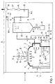
- a factory hall 1 is indicated very schematically, in who installs a grinding booth assembly designated as a whole by 2 is. Several of these arrangements 2 can be in a common factory 1 installed.
- Each such arrangement 2 has a walk-in grinding booth as the centerpiece 3 with side walls 4, a coverable entrance 5 in the form of a Slat curtain 6 and a grid-like ceiling 7.
- Each cabin 3 is supplied with supply air by a ventilation device B.
- ventilation modules 8 are used, which supply air 9 directly relate from the interior of factory hall 1, as is done by the others Arrow 10 is indicated.
- the individual ventilation modules 8 are commercially available, ready-to-connect units with a fan, filter and muffler, such as those from the company Meissner + Wurst GmbH & Co. under the name Filter Fan Units "are offered for clean room technology. They essentially have a box-shaped housing made of aluminum, in which an electrically operated radial fan works. This can be regulated and monitored by speed, which is why corresponding system cables lead from a central control to the respective ventilation module. As the name already suggests indicates that filters for the supply air and silencers are also integrated in the ventilation modules 8, so that there is no acoustic nuisance even when covering the entire surface with modules.
- the ventilation modules generate 8 an air flow in the grinding cabin 3, which is laminar from above runs down. This removes grinding dust from the head area the grinder 12 kept away, which is an inhalation of dusts effectively prevented.
- the ventilation modules 8 with a common cooling arrangement arranged in front of it 14 provided that a fan 15 and a correspondingly designed Heat exchanger 16 exists.
- the dust extraction device designated as a whole is to the Grinding cabin 3 via a detection device 17 with a rotating flow connected.
- the suction device A must - for example for use when grinding aluminum body parts - for a high explosion potential.
- Aluminum particles in air are extremely reactive and can be activated due to the lowest activation potential lead to dust explosions.
- all tubes 18 are for Exhaust air duct designed as seamlessly flanged stainless steel pipes. That from the detection device 17 outgoing pipe 18.1 leads over a Explosion quick-closing slide 19 to a dry filter 20, which acts as a container in a pressure-resistant design for an expected explosion pressure of 10 bar.
- the raw gas side before the dry filter 20 arranged quick-action slide valve 19 closes the exhaust air line suddenly rising pressure within a few milliseconds.
- the dry filter 20 On the clean gas side, the dry filter 20 has an explosion protection valve 21 subordinate, that automatically with increasing pressure - without external drive like the slide 19 - closes.
- the dry filter 20 is in the remaining connected to the collecting container 22 for the aluminum dust.
- the connecting line 18.2 there is a double slide system that is pressure-shock resistant to 10 bar 23.
- the cleaned exhaust air is led to the outside via the exhaust air line 18.3. the latter in the direction of flow 24 of the exhaust air after the explosion protection valve 21 a motor-controlled closure flap 25, a fan 26, a silencer 27 and a bushing 28 in the building ceiling 13 has.
- a motor-controlled closure flap 25 In the bushing 28 is a water trap integrated against ingress of rainwater.
- Two ejectors 36, 37 are connected via corresponding branch lines 35 supplied with compressed air, at the suction connection of the two suction lines 30 or 32 are connected. The one for the supply of the tool extraction
- the branch line 35 provided is by its own shut-off valve 38 lockable.
- the two branch lines 35 open before Rapid shot slide 19 in the exhaust air line 24 of the suction device A.
- the dry filter 20 has another Line 18.4 is connected to the exhaust line 18.3 and before the bushing 28 flows into. There is a solenoid valve 39 in line 18.4 arranged, which is opened when the system is at a standstill and for the removal of Hydrogen from the dry filter 20 leads.
- Hydrogen is produced from the reaction of aluminum dust with that due to the natural humidity in the dry filter 20 existing water vapor.
Landscapes
- Engineering & Computer Science (AREA)
- Mechanical Engineering (AREA)
- Ventilation (AREA)
- Grinding-Machine Dressing And Accessory Apparatuses (AREA)
- Prevention Of Fouling (AREA)
- Working Measures On Existing Buildindgs (AREA)
- Grinding And Polishing Of Tertiary Curved Surfaces And Surfaces With Complex Shapes (AREA)
Applications Claiming Priority (2)
| Application Number | Priority Date | Filing Date | Title |
|---|---|---|---|
| DE29820577U DE29820577U1 (de) | 1998-11-18 | 1998-11-18 | Schleifkabinenanordnung zum Einbau in Gebäude |
| DE29820577U | 1998-11-18 |
Publications (2)
| Publication Number | Publication Date |
|---|---|
| EP1003003A2 true EP1003003A2 (fr) | 2000-05-24 |
| EP1003003A3 EP1003003A3 (fr) | 2003-05-21 |
Family
ID=8065471
Family Applications (1)
| Application Number | Title | Priority Date | Filing Date |
|---|---|---|---|
| EP99122605A Withdrawn EP1003003A3 (fr) | 1998-11-18 | 1999-11-13 | Dispositif pour salle de meulage pour construire dans un bâtiment |
Country Status (2)
| Country | Link |
|---|---|
| EP (1) | EP1003003A3 (fr) |
| DE (1) | DE29820577U1 (fr) |
Cited By (3)
| Publication number | Priority date | Publication date | Assignee | Title |
|---|---|---|---|---|
| WO2004067229A1 (fr) * | 2003-01-22 | 2004-08-12 | Oellerich Joern | Procede de preparation de surfaces de matieres plastiques renforcees par des fibres de carbone permettant d'obtenir des pieces structurelles portantes |
| CN111113220A (zh) * | 2019-11-14 | 2020-05-08 | 湖州双金机械配件有限公司 | 一种用于高锰铸钢生产浇注用辅助装置 |
| CN112108999A (zh) * | 2020-09-27 | 2020-12-22 | 宁波博尔钛新能源设备有限公司 | 一种打磨除尘装置 |
Family Cites Families (4)
| Publication number | Priority date | Publication date | Assignee | Title |
|---|---|---|---|---|
| US2696910A (en) * | 1948-06-09 | 1954-12-14 | Svenska Flaektfabriken Ab | Method and apparatus for separating waste particles from media used in sandblasting |
| US3407719A (en) * | 1967-04-28 | 1968-10-29 | Zero Mfg Company | Blast room with uniform down-draft ventilation |
| US5063834A (en) * | 1988-06-10 | 1991-11-12 | Halton Oy | Focussed ventilation procedure and focussed ventilation means |
| DE29515615U1 (de) | 1995-10-02 | 1996-03-21 | GOSAG Stahl- und Anlagenbau GmbH, 06308 Klostermansfeld | Arbeitskabinensystem zur Reinigung und Oberflächenbehandlung von Gegenständen |
-
1998
- 1998-11-18 DE DE29820577U patent/DE29820577U1/de not_active Expired - Lifetime
-
1999
- 1999-11-13 EP EP99122605A patent/EP1003003A3/fr not_active Withdrawn
Cited By (4)
| Publication number | Priority date | Publication date | Assignee | Title |
|---|---|---|---|---|
| WO2004067229A1 (fr) * | 2003-01-22 | 2004-08-12 | Oellerich Joern | Procede de preparation de surfaces de matieres plastiques renforcees par des fibres de carbone permettant d'obtenir des pieces structurelles portantes |
| CN111113220A (zh) * | 2019-11-14 | 2020-05-08 | 湖州双金机械配件有限公司 | 一种用于高锰铸钢生产浇注用辅助装置 |
| CN111113220B (zh) * | 2019-11-14 | 2021-06-01 | 湖州双金机械配件有限公司 | 一种用于高锰铸钢生产浇注用辅助装置 |
| CN112108999A (zh) * | 2020-09-27 | 2020-12-22 | 宁波博尔钛新能源设备有限公司 | 一种打磨除尘装置 |
Also Published As
| Publication number | Publication date |
|---|---|
| EP1003003A3 (fr) | 2003-05-21 |
| DE29820577U1 (de) | 1999-01-28 |
Similar Documents
| Publication | Publication Date | Title |
|---|---|---|
| CH708655A1 (de) | Luftreinigungsgerät mit Ozon- und Feinstaubreinigung. | |
| DE102008037503A1 (de) | Automatikimpuls-Patronenreinigungssystem und -Verfahren | |
| DE60130105T2 (de) | Verfahren und vorrichtung zur luftfiltration | |
| DE19825420A1 (de) | Verfahren und Vorrichtung zur Rauchgas- und Wärmeabsaugung sowie zur Betriebslüftung für Verkehrsbauten und Räume | |
| EP2418431B1 (fr) | Dispositif de climatisation doté d'un dispositif de conditionnement de l'air | |
| EP3881923B1 (fr) | Séparateur d'aérosol, ainsi que procédé d'installation d'un élément de filtre à coalescence dans un séparateur d'aérosol | |
| DE202007001644U1 (de) | Modular aufgebaute Lüftungseinrichtung für den Einsatz im Reinraum | |
| EP1003003A2 (fr) | Dispositif pour salle de meulage pour construire dans un bâtiment | |
| WO2008107429A1 (fr) | Procédé pour prétraiter l'air pour un appareil de climatisation de véhicule sur rails | |
| EP1862744B1 (fr) | Système d'aération de pièce | |
| DE20209031U1 (de) | Belüftungssystem zur Raumbe- und -entlüftung | |
| DE102017105292A1 (de) | Karosseriearbeitsplatz zur Bearbeitung von Fahrzeugkarosserien | |
| EP3916314B1 (fr) | Système de ventilation | |
| DE102015203668A1 (de) | Schienenfahrzeug mit Traktionskühlanlage | |
| DE10255172A1 (de) | Raumlüftungsgerät | |
| DE4406539C2 (de) | Verfahren und Vorrichtung zum Betrieb einer Zentralabsauganlage insbesondere für holzverarbeitende Betriebe, womit ein Mindestwert des Gesamtvolumenstromes im Abluftsammelrohr aufrechterhalten wird | |
| DE102006007814A1 (de) | Vorrichtung zur Gewährleistung eines sicheren Betriebes einer in einem Aufstellraum vorgesehenen Feuerstelle | |
| DE9403123U1 (de) | Schutzbelüftungsanlage | |
| EP1861270B1 (fr) | Dispositif de separation prealable de particules de poussiere grossieres, destine a des systemes de climatisation de vehicules automobiles | |
| DE2745406A1 (de) | Kompaktfilteranlage mit schalldaempfung | |
| DE19703257A1 (de) | Vorrichtung zum Absaugen und Transportieren von staub- und/oder spanförmigen Abfällen, Granulat oder dergleichen | |
| EP1612490B1 (fr) | Dispositif de ventilation pour la climatisation d'un local | |
| DE102024138004A1 (de) | Lüftungsanlage, insbesondere zum Lüften eines Gebäudes, mit verbessertem Brandschutz, Lüftungsgerät und Verschlusseinrichtung für eine solche, sowie Vorrichtung zum Nutzen von Wärme umfassend eine solche Lüftungsanlage | |
| EP1336803A2 (fr) | Dispositif pour l'extraction et la ventilation d'un local | |
| DE3626393C2 (de) | Anordnung zur Luftfilterung für Kraftfahrzeuge |
Legal Events
| Date | Code | Title | Description |
|---|---|---|---|
| PUAI | Public reference made under article 153(3) epc to a published international application that has entered the european phase |
Free format text: ORIGINAL CODE: 0009012 |
|
| AK | Designated contracting states |
Kind code of ref document: A2 Designated state(s): AT BE CH CY DE DK ES FI FR GB GR IE IT LI LU MC NL PT SE |
|
| AX | Request for extension of the european patent |
Free format text: AL;LT;LV;MK;RO;SI |
|
| PUAL | Search report despatched |
Free format text: ORIGINAL CODE: 0009013 |
|
| AK | Designated contracting states |
Designated state(s): AT BE CH CY DE DK ES FI FR GB GR IE IT LI LU MC NL PT SE |
|
| AX | Request for extension of the european patent |
Extension state: AL LT LV MK RO SI |
|
| RIC1 | Information provided on ipc code assigned before grant |
Ipc: 7B 24C 9/00 B Ipc: 7B 24B 55/06 B Ipc: 7F 24F 3/16 A |
|
| RIN1 | Information on inventor provided before grant (corrected) |
Inventor name: LOY, JUERGEN |
|
| 17P | Request for examination filed |
Effective date: 20030617 |
|
| AKX | Designation fees paid |
Designated state(s): AT BE CH CY DE DK ES FI FR GB GR IE IT LI LU MC NL PT SE |
|
| GRAP | Despatch of communication of intention to grant a patent |
Free format text: ORIGINAL CODE: EPIDOSNIGR1 |
|
| STAA | Information on the status of an ep patent application or granted ep patent |
Free format text: STATUS: THE APPLICATION IS DEEMED TO BE WITHDRAWN |
|
| 18D | Application deemed to be withdrawn |
Effective date: 20050301 |