EP1002622B1 - Abstützeinrichtung für ein stangenartiges Werkstück an einer Bearbeitungsmaschine - Google Patents
Abstützeinrichtung für ein stangenartiges Werkstück an einer Bearbeitungsmaschine Download PDFInfo
- Publication number
- EP1002622B1 EP1002622B1 EP99122603A EP99122603A EP1002622B1 EP 1002622 B1 EP1002622 B1 EP 1002622B1 EP 99122603 A EP99122603 A EP 99122603A EP 99122603 A EP99122603 A EP 99122603A EP 1002622 B1 EP1002622 B1 EP 1002622B1
- Authority
- EP
- European Patent Office
- Prior art keywords
- workpiece
- support body
- roller
- receptacle
- support
- Prior art date
- Legal status (The legal status is an assumption and is not a legal conclusion. Google has not performed a legal analysis and makes no representation as to the accuracy of the status listed.)
- Expired - Lifetime
Links
- 239000002184 metal Substances 0.000 claims description 3
- 238000003754 machining Methods 0.000 description 9
- 238000003698 laser cutting Methods 0.000 description 5
- 230000006978 adaptation Effects 0.000 description 2
- 238000007599 discharging Methods 0.000 description 2
- 238000006073 displacement reaction Methods 0.000 description 2
- 230000002093 peripheral effect Effects 0.000 description 2
- 238000005452 bending Methods 0.000 description 1
- 238000010276 construction Methods 0.000 description 1
- 238000000034 method Methods 0.000 description 1
Images

Classifications
-
- B—PERFORMING OPERATIONS; TRANSPORTING
- B23—MACHINE TOOLS; METAL-WORKING NOT OTHERWISE PROVIDED FOR
- B23K—SOLDERING OR UNSOLDERING; WELDING; CLADDING OR PLATING BY SOLDERING OR WELDING; CUTTING BY APPLYING HEAT LOCALLY, e.g. FLAME CUTTING; WORKING BY LASER BEAM
- B23K26/00—Working by laser beam, e.g. welding, cutting or boring
- B23K26/08—Devices involving relative movement between laser beam and workpiece
- B23K26/0823—Devices involving rotation of the workpiece
-
- B—PERFORMING OPERATIONS; TRANSPORTING
- B23—MACHINE TOOLS; METAL-WORKING NOT OTHERWISE PROVIDED FOR
- B23K—SOLDERING OR UNSOLDERING; WELDING; CLADDING OR PLATING BY SOLDERING OR WELDING; CUTTING BY APPLYING HEAT LOCALLY, e.g. FLAME CUTTING; WORKING BY LASER BEAM
- B23K26/00—Working by laser beam, e.g. welding, cutting or boring
- B23K26/08—Devices involving relative movement between laser beam and workpiece
- B23K26/083—Devices involving movement of the workpiece in at least one axial direction
- B23K26/0838—Devices involving movement of the workpiece in at least one axial direction by using an endless conveyor belt
- B23K26/0846—Devices involving movement of the workpiece in at least one axial direction by using an endless conveyor belt for moving elongated workpieces longitudinally, e.g. wire or strip material
-
- B—PERFORMING OPERATIONS; TRANSPORTING
- B23—MACHINE TOOLS; METAL-WORKING NOT OTHERWISE PROVIDED FOR
- B23Q—DETAILS, COMPONENTS, OR ACCESSORIES FOR MACHINE TOOLS, e.g. ARRANGEMENTS FOR COPYING OR CONTROLLING; MACHINE TOOLS IN GENERAL CHARACTERISED BY THE CONSTRUCTION OF PARTICULAR DETAILS OR COMPONENTS; COMBINATIONS OR ASSOCIATIONS OF METAL-WORKING MACHINES, NOT DIRECTED TO A PARTICULAR RESULT
- B23Q1/00—Members which are comprised in the general build-up of a form of machine, particularly relatively large fixed members
- B23Q1/72—Auxiliary arrangements; Interconnections between auxiliary tables and movable machine elements
- B23Q1/76—Steadies; Rests
Definitions
- the invention relates to a support device for a rod-like Workpiece, in particular a metal tube, on a processing machine, the workpiece being at the processing machine about an axis of rotation extending in its longitudinal direction is rotatably supported, with at least one support body, the one Receiving for the workpiece, on the wall of the Workpiece is supported in the radial direction, the points the workpiece support in the vertical projection in a Cross-sectional plane of the workpiece along one with the axis of rotation of the workpiece concentric circumference are arranged according to the preamble of claim 1, e.g. out known from US-A-4018115.
- a Popeerdem is known a support device with a support body, its recording for the workpiece in the manner of a V-shaped Groove is formed.
- the workpiece can be in the Turn the machining around its longitudinal axis. Just like that can be a functional rotation only under the condition be accomplished that the relevant workpiece has a circular cross-section.
- the support of workpieces with deviating from the circular cross-section requires additional Precautions. This is the state of the art for this Case circular discs in front, with a cross section of the are provided for processing workpiece adapted breakthrough and slid in the longitudinal direction of the workpiece on this become.
- V-shaped groove of the support body can be the workpiece concerned then with the circular outer contour store the disc pushed onto the workpiece. Accordingly is before any machining of a workpiece with a cross-section deviating from the circular shape, with multiple support several discs of the type described above to apply to the relevant workpiece. This condition makes automated workpiece machining difficult, though not impossible.
- the present invention set to the goal.
- the stated object is achieved in that in the case of a generic support device the walls of the receiving parts in the vertical projection in the cross-sectional plane of the Workpiece are formed with a radius which the radius corresponds to the circumference of the workpiece.
- the multipart Training of the support body and the described relative mobility The support body parts create the opportunity to Support body in the radial direction of the workpiece to open and put on the workpiece, without that for this purpose Relative movement of support body or support body parts and Workpiece in the axial direction of the workpiece would be required.
- the automation of the workpiece change and thus of the entire Machining process is therefore very easy.
- Automation of workpiece machining also serves this purpose specified in claim 2 feature of the support device according to the invention.
- the respective support body part for the workpiece supply or for workpiece removal at the processing station used in the processing machine are specified in claim 2 feature of the support device according to the invention.
- the program control of the support body parts described in claim 6 serves the automation of workpiece machining.
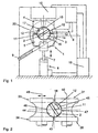
- Figure 1 comprises a support means 1 for a rod-like workpiece, in this case a metal tube 2 with Rectangular cross section, a support body 3, consisting of a upper support body part 4 and a lower support body part 5.
- the upper support body part 4 is, as indicated, on the frame attached to a processing machine 6.
- the lower support body part 5 is with a piston rod 7 of a piston-cylinder unit 8 connected.
- a chute 9 for discharging the Workpiece 2 provided after the processing. Processed the workpiece 2 is in the form of a processing station a laser cutting head 10 of the processing machine 6.
- the receptacle 13 for the workpiece 2 is formed by receiving parts 14, 15 on the support body parts 4, 5.
- walls 16, 17 the receiving parts 14, 15 extend - in the vertical projection in a matching with the plane of Figure 1
- Cross-sectional plane of the workpiece 2 - circular arc around a imaginary common center, by the axis of rotation 11 of the workpiece 2 is defined.
- the Walls 16, 17 together with a dot-dash line in Figure 1 indicated perimeter 18 of the axis of rotation 11 of the workpiece 2.
- Auf arranged around the perimeter 18 are the four corners of the rectangular cross section of the workpiece 2. This is supported by these corners Workpiece 2 in the radial direction on the walls 16, 17 of the Receiving parts 14, 15 on the support body parts 4, 5 from.
- the workpiece is 2 initially supply the processing machine 6. It is the lower support body part 5 initially by means of the piston-cylinder unit 8 in the radial direction of the workpiece 2 relative to move the upper support body part 4 in its lower rest position and consequently with the support body 3 open, with relative a large distance from the upper support body part 4 is arranged. Subsequently, the workpiece 2 at its axial ends in the chucks of the machine-side turning devices 20 clamped and then penetrates the gap between the Support body parts 4, 5. Now, the lower support body part 5 by means of the piston-cylinder unit 8 up into its working position to be moved according to FIG. In this situation becomes the support body part 5 during the machining of the workpiece 2 held by the piston-cylinder unit 8.
- the workpiece 2 is attached to a support device 31, which has a support body 33.
- the roller axes of rotation 49, 50 lie in the coincident with the plane of Figure 2 Cross-sectional plane of the workpiece 2.
- Each of the rollers 34, 35 is with a recessed in their coat groove 44, 45th provided, which extends over the entire roll circumference.
- the fillets 44, 45 are receiving parts, taken together a receptacle 43 of the support body 33 form.
- Walls 46, 47 of the flutes 44, 45 are in the shown vertical projection in the cross-sectional plane of the Workpiece 1 is formed with a radius which corresponds to the radius of the circumcircle 18 on the workpiece 2 corresponds.
- Support body parts 4, 5 of Figure 1 are the rollers 34, 35 according to Figure 2 in the horizontal direction relative to each other movable. Due to its rotation about the roller axes of rotation 49, 50 as well due to the fact that the walls 46, 47 of the fillets 44, 45 in the direction of rotation of the rollers 34, 35 a constant Radius, the rollers 34, 35 at rotate and allow any axial movements of the workpiece 2 then a low-friction displacement of the inside of the recording 43 held workpiece 2 in the axial direction.
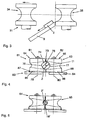
- a support 61 makes use from a support body 63 consisting of two support body parts in the form of rollers 64, 65.
- the latter are roller pivot axes 79, 80 rotatably adjustable and in each set Rotary position by means of locking devices 81, 82nd can be fixed by an axial bracing against an abutment.
- FIG. 4 shows a receptacle 73 for the workpiece 2 from receiving parts 74, 75, which in turn of corresponding Coves are formed.
- the flutes or receiving parts 74, 75 are in the jacket of the respective roller 64, 65th sunk in and each extend over a large part of the roll circumference.
- Walls 76, 77 of the flutes 74, 75 are in the direction of adjustment of the rollers 64, 65 variable radii educated. By adjusting the rollers 64, 65 around the roller rotation axis 79, 80 can consequently be the radius or the diameter change the recording 73. According to Figure 4, the walls form 76, 77 of the flutes 74, 75, the receptacle 73 with a Radius from which the radius of the circumference 18 of the workpiece 2 corresponds.
- rollers 64, 65 are shown in rotational positions, in which the walls 76, 77 of the flutes 74, 75 with minimal Radius in the cross-sectional plane of a workpiece 2 ' are opposite.
- the radius corresponds to the walls 76, 77 at the flutes 74, 75 the radius of a circumference 18 'of the workpiece 2'.
- FIGS. 4 and 5 Indicated in FIGS. 4 and 5 are display devices 83, 84, on the basis of which occupied by the rollers 64, 65 rotary position and thus the set radius of the receptacle 73 recognizable is.
- the display devices 83, 84 staggered in the direction of adjustment of the rollers 64, 65 against each other Markers 85, 86. These are associated with pointers 87, 88.
- FIG. 6 shows the roller 64 of FIGS. 4 and 5 in an individual view.
- rollers 34, 35 and the rollers 64, 65 in horizontal Direction relative to each other movable.
- rollers 34, 35 and the rollers 64, 65 in horizontal Direction relative to each other movable.
- FIG. 7 shows a support body part 94, which together with a corresponding support body part, not shown forms a support body 93 of a support 91.
- the support body part 94 is a support body part rotation axis 109 rotationally adjustable and in the same way as the Rollers 64, 65 according to Figures 4 and 5 in each set Rotary position fixable.
- the support body part 94 in the adjustment direction against each other staggered receiving parts 104, 110, wherein walls 106, 111 are formed with different radii.
- the the Support body part 94 associated second support body part is corresponding designed so that by adjusting the two support body parts around the respective support body part axis of rotation an adaptation the support 91 to two different workpiece perimeter radii or diameter can be made.
- construction and operation corresponds to the support device 91 otherwise the support devices described in detail above 1, 31, 61.
Landscapes
- Engineering & Computer Science (AREA)
- Physics & Mathematics (AREA)
- Optics & Photonics (AREA)
- Mechanical Engineering (AREA)
- Plasma & Fusion (AREA)
- Jigs For Machine Tools (AREA)
- Turning (AREA)
- Feeding Of Workpieces (AREA)
- Laser Beam Processing (AREA)
- Machine Tool Units (AREA)
Description
- Figur 1
- eine erste Ausführungsform einer Abstützeinrichtung an einer Bearbeitungsmaschine,
- Figur 2
- eine zweite Ausführungsform einer Abstützeinrichtung,
- Figur 3
- die Abstützeinrichtung nach Figur 2 beim Ausschleusen eines bearbeiteten Werkstückes,
- Figuren 4 und 5
- eine dritte Ausführungsform einer Abstützeinrichtung mit unterschiedlichen Einstellungen,
- Figur 6
- einen der Stützkörperteile der Abstützeinrichtung nach den Figuren 4 und 5 in Einzeldarstellung und
- Figur 7
- einen Stützkörperteil einer vierten Ausführungsform einer Abstützeinrichtung in Einzeldarstellung.
Claims (6)
- Abstützeinrichtung für ein stangenartiges Werkstück (2, 2'), insbesondere ein Metallrohr, an einer Bearbeitungsmaschine (6), wobei das Werkstück (2, 2') an der Bearbeitungsmaschine (6) um eine in seiner Längsrichtung verlaufende Drehachse (11) drehbar gehalten ist, mit wenigstens einem Stützkörper (3, 33, 63, 93), der eine Aufnahme (13, 43, 73) für das Werkstück (2, 2') aufweist, an deren Wandung das Werkstück (2, 2') in radialer Richtung abgestützt ist, wobei die Punkte der Werkstückabstützung in der senkrechten Projektion in eine Querschnittsebene des Werkstückes (2, 2') entlang eines mit der Drehachse (11) des Werkstückes (2, 2') konzentrischen Umkreises (18, 18') angeordnet sind, wobei der Stützkörper (3, 33, 63, 93) mehrteilig ausgebildet ist mit wenigstens zwei Stützkörperteilen (4, 5; 34, 35; 64, 65; 94), die in radialer Richtung des Werkstücks (2, 2') relativ zueinander beweglich sind und mit Aufnahmeteilen (14, 15; 44, 45; 74, 75; 104, 110) die Aufnahme (13, 43, 73) für das Werkstück (2, 2') ausbilden, dadurch gekennzeichnet, daß die Wandungen (16, 17; 46, 47; 76, 77; 106, 111) der Aufnahmeteile (14, 15; 44, 45; 74, 75; 104, 110) in der senkrechten Projektion in die Querschnittsebene des Werkstücks (2, 2') mit einem Radius ausgebildet sind, welcher dem Radius des Umkreises (18, 18') des Werkstückes (2, 2') entspricht.
- Abstützeinrichtung nach Anspruch 1, dadurch gekennzeichnet, daß wenigstens einer (5) der Stützkörperteile (4, 5) das Werkstück (2) untergreift und gemeinsam mit diesem relativ zu einer Bearbeitungsstation (10) der Bearbeitungsmaschine (6) bewegbar ist.
- Abstützeinrichtung nach einem der vorhergehenden Ansprüche, dadurch gekennzeichnet, daß wenigstens einer der Stützkörperteile (34, 35) als Rolle ausgebildet ist, die um eine in einer Querschnittsebene des Werkstücks (2) verlaufende Rollen-Drehachse (49, 50) drehbar ist sowie eine in ihren Mantel eingesenkte und den Aufnahmeteil (44, 45) der Rolle bildende Hohlkehle aufweist, die in Rollen-Drehrichtung über wenigstens einen Teil des Rollenumfangs verläuft und deren Wandung (46, 47) wenigstens teilweise mit in Rollen-Drehrichtung gleichbleibendem Radius ausgebildet ist.
- Abstützeinrichtung nach einem der vorhergehenden Ansprüche, dadurch gekennzeichnet, daß wenigstens einer (94) der Stützkörperteile um eine Stützkörperteil-Drehachse (109) drehend einstellbar ist und in Einstellrichtung gegeneinander versetzte Aufnahmeteile (104, 110) aufweist, deren Wandungen (106, 111) mit unterschiedlichen Radien ausgebildet sind.
- Abstützeinrichtung nach einem der vorhergehenden Ansprüche, dadurch gekennzeichnet, daß wenigstens einer der Stützkörperteile (64, 65) als Rolle ausgebildet ist, die um eine in einer Querschnittsebene des Werkstücks (2, 2') verlaufende Rollen-Drehachse (79, 80) drehend einstellbar ist sowie eine in ihren Mantel eingesenkte und den Aufnahmeteil (74, 75) der Rolle bildende Hohlkehle aufweist, die in Rollen-Einstellrichtung über wenigstens einen Teil des Rollenumfangs verläuft und deren Wandung (76, 77) wenigstens teilweise mit in Rollen-Einstellrichtung veränderlichem Radius ausgebildet ist.
- Abstützeinrichtung nach einem der vorhergehenden Ansprüche, dadurch gekennzeichnet, daß die Stützkörperteile (4, 5; 34, 35; 64, 65; 94) programmgesteuert relativ zueinander beweglich und/oder um die Stützkörperteil- (109) bzw. Rollen-Drehachse (79, 80) drehend einstellbar sind.
Applications Claiming Priority (2)
| Application Number | Priority Date | Filing Date | Title |
|---|---|---|---|
| DE29820779U DE29820779U1 (de) | 1998-11-20 | 1998-11-20 | Abstützeinrichtung für ein stangenartiges Werkstück an einer Bearbeitungsmaschine |
| DE29820779U | 1998-11-20 |
Publications (3)
| Publication Number | Publication Date |
|---|---|
| EP1002622A2 EP1002622A2 (de) | 2000-05-24 |
| EP1002622A3 EP1002622A3 (de) | 2003-01-02 |
| EP1002622B1 true EP1002622B1 (de) | 2004-06-23 |
Family
ID=8065610
Family Applications (1)
| Application Number | Title | Priority Date | Filing Date |
|---|---|---|---|
| EP99122603A Expired - Lifetime EP1002622B1 (de) | 1998-11-20 | 1999-11-13 | Abstützeinrichtung für ein stangenartiges Werkstück an einer Bearbeitungsmaschine |
Country Status (3)
| Country | Link |
|---|---|
| EP (1) | EP1002622B1 (de) |
| AT (1) | ATE269777T1 (de) |
| DE (2) | DE29820779U1 (de) |
Cited By (2)
| Publication number | Priority date | Publication date | Assignee | Title |
|---|---|---|---|---|
| US8404997B2 (en) | 2007-07-17 | 2013-03-26 | Trumpf Werkzeugmaschinen Gmbh + Co. Kg | Machine arrangement for machining bar-like workpieces having a device for workpiece support |
| DE102012209079B3 (de) * | 2012-05-30 | 2013-09-26 | Trumpf Werkzeugmaschinen Gmbh + Co. Kg | Verfahren zur Bearbeitung von stabartigen Werkstücken, Bearbeitungsmaschine und Abstützeinrichtung |
Families Citing this family (2)
| Publication number | Priority date | Publication date | Assignee | Title |
|---|---|---|---|---|
| EP2492041B1 (de) | 2011-02-25 | 2015-01-14 | TRUMPF Werkzeugmaschinen GmbH + Co. KG | Flexible Vorrichtung mit einer Rohrbearbeitungsvorrichtung ; Verfahren zum Entladen eines Rohres unter Verwendung einer solchen Vorrichtung |
| EP3747591A1 (de) * | 2019-06-06 | 2020-12-09 | Bystronic Laser AG | Haltevorrichtung, werkzeugmaschine und verfahren zum tragen eines stabförmigen werkstücks |
Family Cites Families (5)
| Publication number | Priority date | Publication date | Assignee | Title |
|---|---|---|---|---|
| FR923640A (fr) * | 1946-02-08 | 1947-07-11 | Machine à tailler par génération | |
| US4018115A (en) * | 1976-03-29 | 1977-04-19 | Camco, Incorporated | Self-centering steady rest for a machine tool |
| JPS5953125A (ja) * | 1982-09-20 | 1984-03-27 | Nippon Kokan Kk <Nkk> | 放電加工装置 |
| DE4019285A1 (de) | 1990-06-16 | 1991-12-19 | Kieserling & Albrecht | Spanneinrichtung zum gezielten spannen von werkstuecken |
| DE4137071C2 (de) | 1991-11-12 | 1994-04-14 | Kieserling & Albrecht | Führung zum spitzenlosen, radialen Führen von axial bewegten Stangen |
-
1998
- 1998-11-20 DE DE29820779U patent/DE29820779U1/de not_active Expired - Lifetime
-
1999
- 1999-11-13 EP EP99122603A patent/EP1002622B1/de not_active Expired - Lifetime
- 1999-11-13 AT AT99122603T patent/ATE269777T1/de not_active IP Right Cessation
- 1999-11-13 DE DE59909801T patent/DE59909801D1/de not_active Expired - Lifetime
Cited By (2)
| Publication number | Priority date | Publication date | Assignee | Title |
|---|---|---|---|---|
| US8404997B2 (en) | 2007-07-17 | 2013-03-26 | Trumpf Werkzeugmaschinen Gmbh + Co. Kg | Machine arrangement for machining bar-like workpieces having a device for workpiece support |
| DE102012209079B3 (de) * | 2012-05-30 | 2013-09-26 | Trumpf Werkzeugmaschinen Gmbh + Co. Kg | Verfahren zur Bearbeitung von stabartigen Werkstücken, Bearbeitungsmaschine und Abstützeinrichtung |
Also Published As
| Publication number | Publication date |
|---|---|
| ATE269777T1 (de) | 2004-07-15 |
| EP1002622A3 (de) | 2003-01-02 |
| DE59909801D1 (de) | 2004-07-29 |
| DE29820779U1 (de) | 1999-02-25 |
| EP1002622A2 (de) | 2000-05-24 |
Similar Documents
| Publication | Publication Date | Title |
|---|---|---|
| EP1260294B1 (de) | Verfahren und Vorrichtung zur Drehbearbeitung | |
| DE3720180C1 (de) | Wechselvorrichtung fuer eine Werkzeugmaschine | |
| EP2392438B1 (de) | Bearbeitungsvorrichtung | |
| EP2965845B1 (de) | Werkzeugrevolver | |
| DE69000888T2 (de) | Verfahren und vorrichtung zum abschraegen von einspringenden ecken bei tafeln aus farbigem oder nicht farbigem flachglas. | |
| DE19854276A1 (de) | Werkzeugmaschinen-Anordnung mit einer Vorrichtung für einen automatischen Werkzeugwechsel | |
| EP0535201B1 (de) | Verfahren zum honen von bohrungen | |
| DE2648388C2 (de) | Vorrichtung zum Walzen von Lagerringen | |
| DE2217505B2 (de) | Dorniagerung einer Vorrichtung zum Konifizieren von Rohren | |
| EP0360953B1 (de) | Maschine zum Feinbearbeiten der Zahnflanken von verzahnten Werkstücken | |
| DE10258549A1 (de) | Verfahren und Vorrichtung zum Entgraten von Zahnrädern | |
| EP1002622A2 (de) | Abstützeinrichtung für ein stangenartiges Werkstück an einer Bearbeitungsmaschine | |
| EP0787560A1 (de) | Vorrichtung zum Bearbeiten von Stangenmaterial, Profilen und dergleichen | |
| EP3670069B1 (de) | Werkstückabstützung zur abstützung von rohrmaterial in einer rohrbearbeitungsmaschine und rohrbearbeitungsmaschine | |
| DE3734734C2 (de) | ||
| DE2714706C2 (de) | Zahnradfeinbearbeitungsmaschine | |
| DE4215988A1 (de) | Verfahren und Honwerkzeug zum Herstellen konischer Bohrungen | |
| DE10147649C2 (de) | Fräsaggregat | |
| DE4335580A1 (de) | Vorrichtung zum Trennen einer mehrfach hohen Dosenzarge | |
| EP0086934B1 (de) | Verfahren und Walzgerüst zum Auswalzen von Bandmaterial unterschiedlicher Breite | |
| EP0841116A2 (de) | Verfahren zum Bearbeiten von rotationssymmetrischen Werkstückflächen sowie Werkzeug zur Durchführung eines solchen Verfahrens | |
| EP0549821B1 (de) | Verfahren zum Honen von Bohrungen und Honwerkzeug zur Durchführung des Verfahrens | |
| DE172215C (de) | ||
| DE10024105C2 (de) | Ringwalzvorrichtung | |
| DE2224761A1 (de) | Werkzeugmaschine |
Legal Events
| Date | Code | Title | Description |
|---|---|---|---|
| PUAI | Public reference made under article 153(3) epc to a published international application that has entered the european phase |
Free format text: ORIGINAL CODE: 0009012 |
|
| AK | Designated contracting states |
Kind code of ref document: A2 Designated state(s): AT BE CH CY DE DK ES FI FR GB GR IE IT LI LU MC NL PT SE |
|
| AX | Request for extension of the european patent |
Free format text: AL;LT;LV;MK;RO;SI |
|
| PUAL | Search report despatched |
Free format text: ORIGINAL CODE: 0009013 |
|
| AK | Designated contracting states |
Kind code of ref document: A3 Designated state(s): AT BE CH CY DE DK ES FI FR GB GR IE IT LI LU MC NL PT SE |
|
| AX | Request for extension of the european patent |
Free format text: AL;LT;LV;MK;RO;SI |
|
| RIC1 | Information provided on ipc code assigned before grant |
Free format text: 7B 23Q 1/76 A, 7B 23K 26/08 B |
|
| 17P | Request for examination filed |
Effective date: 20021218 |
|
| AKX | Designation fees paid |
Designated state(s): AT CH DE FR GB IT LI |
|
| GRAP | Despatch of communication of intention to grant a patent |
Free format text: ORIGINAL CODE: EPIDOSNIGR1 |
|
| GRAS | Grant fee paid |
Free format text: ORIGINAL CODE: EPIDOSNIGR3 |
|
| RAP1 | Party data changed (applicant data changed or rights of an application transferred) |
Owner name: TRUMPF WERKZEUGMASCHINEN GMBH + CO. KG |
|
| GRAA | (expected) grant |
Free format text: ORIGINAL CODE: 0009210 |
|
| AK | Designated contracting states |
Kind code of ref document: B1 Designated state(s): AT CH DE FR GB IT LI |
|
| REG | Reference to a national code |
Ref country code: GB Ref legal event code: FG4D Free format text: NOT ENGLISH |
|
| REG | Reference to a national code |
Ref country code: CH Ref legal event code: EP |
|
| REG | Reference to a national code |
Ref country code: IE Ref legal event code: FG4D Free format text: GERMAN |
|
| REF | Corresponds to: |
Ref document number: 59909801 Country of ref document: DE Date of ref document: 20040729 Kind code of ref document: P |
|
| GBT | Gb: translation of ep patent filed (gb section 77(6)(a)/1977) |
Effective date: 20040823 |
|
| PG25 | Lapsed in a contracting state [announced via postgrant information from national office to epo] |
Ref country code: AT Free format text: LAPSE BECAUSE OF NON-PAYMENT OF DUE FEES Effective date: 20041113 |
|
| REG | Reference to a national code |
Ref country code: IE Ref legal event code: FD4D |
|
| ET | Fr: translation filed | ||
| PLBE | No opposition filed within time limit |
Free format text: ORIGINAL CODE: 0009261 |
|
| STAA | Information on the status of an ep patent application or granted ep patent |
Free format text: STATUS: NO OPPOSITION FILED WITHIN TIME LIMIT |
|
| 26N | No opposition filed |
Effective date: 20050324 |
|
| PGFP | Annual fee paid to national office [announced via postgrant information from national office to epo] |
Ref country code: CH Payment date: 20081124 Year of fee payment: 10 |
|
| PGFP | Annual fee paid to national office [announced via postgrant information from national office to epo] |
Ref country code: FR Payment date: 20081118 Year of fee payment: 10 |
|
| PGFP | Annual fee paid to national office [announced via postgrant information from national office to epo] |
Ref country code: GB Payment date: 20081121 Year of fee payment: 10 |
|
| REG | Reference to a national code |
Ref country code: CH Ref legal event code: PL |
|
| GBPC | Gb: european patent ceased through non-payment of renewal fee |
Effective date: 20091113 |
|
| REG | Reference to a national code |
Ref country code: FR Ref legal event code: ST Effective date: 20100730 |
|
| PG25 | Lapsed in a contracting state [announced via postgrant information from national office to epo] |
Ref country code: LI Free format text: LAPSE BECAUSE OF NON-PAYMENT OF DUE FEES Effective date: 20091130 Ref country code: FR Free format text: LAPSE BECAUSE OF NON-PAYMENT OF DUE FEES Effective date: 20091130 Ref country code: CH Free format text: LAPSE BECAUSE OF NON-PAYMENT OF DUE FEES Effective date: 20091130 |
|
| PG25 | Lapsed in a contracting state [announced via postgrant information from national office to epo] |
Ref country code: GB Free format text: LAPSE BECAUSE OF NON-PAYMENT OF DUE FEES Effective date: 20091113 |
|
| PGFP | Annual fee paid to national office [announced via postgrant information from national office to epo] |
Ref country code: DE Payment date: 20181120 Year of fee payment: 20 |
|
| PGFP | Annual fee paid to national office [announced via postgrant information from national office to epo] |
Ref country code: IT Payment date: 20181126 Year of fee payment: 20 |
|
| REG | Reference to a national code |
Ref country code: DE Ref legal event code: R071 Ref document number: 59909801 Country of ref document: DE |