EP1002507A1 - Urinmessgerät - Google Patents
Urinmessgerät Download PDFInfo
- Publication number
- EP1002507A1 EP1002507A1 EP99121233A EP99121233A EP1002507A1 EP 1002507 A1 EP1002507 A1 EP 1002507A1 EP 99121233 A EP99121233 A EP 99121233A EP 99121233 A EP99121233 A EP 99121233A EP 1002507 A1 EP1002507 A1 EP 1002507A1
- Authority
- EP
- European Patent Office
- Prior art keywords
- valve
- housing
- measuring device
- urine
- valve plate
- Prior art date
- Legal status (The legal status is an assumption and is not a legal conclusion. Google has not performed a legal analysis and makes no representation as to the accuracy of the status listed.)
- Granted
Links
Images

Classifications
-
- A—HUMAN NECESSITIES
- A61—MEDICAL OR VETERINARY SCIENCE; HYGIENE
- A61B—DIAGNOSIS; SURGERY; IDENTIFICATION
- A61B5/00—Measuring for diagnostic purposes; Identification of persons
- A61B5/20—Measuring for diagnostic purposes; Identification of persons for measuring urological functions restricted to the evaluation of the urinary system
- A61B5/207—Sensing devices adapted to collect urine
- A61B5/208—Sensing devices adapted to collect urine adapted to determine urine quantity, e.g. flow, volume
Definitions
- the invention relates to a urine measuring device and in particular a Urine meter, which has a drip chamber with a Has anti-reflux valve.
- Urine meters are used to take urine through a Catheter runs out of a patient's body.
- a urine measuring device can germs from the environment immigrate who multiply there. These germs can pass through the connecting hose leading to the patient in the Enter patient's body and urinary tract infection cause.
- Urine meters usually at the mouth of the Connection hose into the measuring container with a Pasteur's Chamber equipped. This consists of a drip chamber with a dropper on the inlet side and an anti-reflux valve on the drain side. In the drip chamber, the Connecting hose interrupted coming liquid column. The urine drips from a dropper tip and falls free through the air without wetting the drip chamber walls. On The pathogens cannot spread to the dry walls move further towards the patient.
- Urine meter perpendicular to the patient's bed. At the end of The urine volume is logged and the The measuring container is emptied into the urine bag. For this, the Measuring container tilted by more than 90 °. The urine flowing back could also use the dropper and the inner walls of the Wet the drip chamber so that the germ barrier would be lifted. To prevent this, it is known to be at the bottom of the drip chamber to provide an anti-reflux valve.
- An anti-reflux valve is in connection with a drip chamber known from DE-PS 25 43 778.
- a Holding member is biased into the closed position.
- the Holding member and the valve flap form a check valve.
- This check valve consists of at least two parts, by which the holding member has a complex shape. Hence the Manufacturing relatively complex.
- Antireflux valve contains a valve chamber with a Valve seat against which a valve disk is pulled.
- the Valve disc is molded in one piece with a support rod, which has resilient anchor elements at the ends.
- This requires the manufacture of the complex valve body considerable effort. It should also be borne in mind that with solids (blood clot, semolina) are also transported to the urine can get stuck in the valve and this keep open.
- a urine meter, at the bottom of a measuring chamber Check valve is provided is known from DE 41 37 074 A1.
- the check valve consists of a Valve plate against one at the bottom of the Presses valve opening provided circumferential valve seat. about the attachment of the valve plate and its function are not Information provided.
- the invention has for its object to provide a urine meter To create drip chamber and anti-reflux valve, in which the Danger of malfunctions due to trapped solid bodies is excluded and which in manufacture and assembly is simple and inexpensive.
- the urine measuring device has a Valve plate on which consists of a freely movable loose part consists. This means that the valve plate is nowhere suspended or firmly attached to other construction parts is. It is a loose moving part.
- the Valve plate is a flat plate that does not come from the Protruding plate level or the like. having. The Valve plate lies against a valve seat from below, if an external force is exerted by pushing back Fluid occurs.
- Valve is integrated in the measuring device housing and is the only one specific additional part only requires the valve plate.
- the parts of the valve housing can be made in one piece in the Measuring housing can be integrated, so that a separate manufacture or assembly is not necessary.
- the valve plate is a flat plate, that does not require a special three-dimensional shape. Rather, it can be made from a suitable flat film material be punched out. It preferably consists of polyester film.
- the valve plate is relatively stiff and dimensionally stable. she consists preferably made of semi-rigid plastic.
- valve plate is between side guide elements kept loose. This means that the valve plate on none Place has a firm connection with the valve housing.
- guide elements form a cage in which the Valve plate is movable. They are arranged so that in each possible position the projection of the valve plate the Valve opening completely covered.
- the lateral guide elements preferably consist of Ribs in from the wall of the valve body protrude, the valve housing having a larger cross section has than the valve opening. So there is a big one Flow cross section available. As a result of the absence elastic clamping device and due to a large free Passage cross section there is no risk that in the urine contained solids hinder the function of the valve.
- the valve is with Exception of the valve plate, integral part of a Meter housing that contains the drip chamber.
- the valve plate is only used for this certain cavity inserted without a fixation would be required.
- this Measuring device housing two assembled housing parts.
- the Valve opening and the guide elements are part of the a housing part and a supporting the valve plate Cantilever arm is the other part of the housing.
- a supporting the valve plate Cantilever arm is the other part of the housing.
- the cross-sectional area of the valve opening is preferably around at least 70% larger than the inside cross-section of the dropper. In this way, the valve opening is of sufficient size ensured to prevent clogging.
- the urine measuring device has a measuring container 10 which consists of a Feinmeßhunt 11 and a coarse measuring chamber 12 exists.
- the Precision measuring chamber and the rough measuring chamber are through a web 13 separated and by an overflow 14 at the upper end of the web 13 connected to each other.
- a drip chamber 15 is arranged above the precision measuring chamber 11, into which a supply hose 16 coming from the patient opens.
- the inlet hose 16 is in a hose fixation 17 attached.
- the inlet hose is glued in such a way that front end a few millimeters into the drip chamber 15 protrudes and forms a dropper 18.
- At the front of the Drip chamber 15 has a ventilation filter 19 attached to it is connected to the ambient air.
- the drip chamber 15, the precision measuring chamber 11 and the rough measuring chamber 12 are part of a two-part housing Measuring device housing.
- One housing component 20 forms that Front part and the other housing component 21 forms that Back part.
- Front and back are through one all-round tongue and groove connection 22 with adhesive or Weld connected.
- the tongue and groove connection 22 extends all around the entire measuring device housing as well along the inner walls.
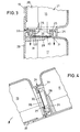
- valve housing 24 is formed in the transition area between drip chamber 15 and Fine measuring chamber 11. This consists of combined components of the two Housing parts 20,21, each one-piece plastic molded parts form.
- the valve housing 24 contains a horizontal partition wall 25, which forms the bottom wall of the drip chamber 15.
- the circular valve opening 26 is contained between the intermediate wall 25.
- the lower edge of the valve opening 26 forms the bead-like circumferential valve seat 27.
- a cantilever arm 28 arranged, of the belonging to the housing part 20 Front wall 29 protrudes inward and approximately parallel to Intermediate wall 25 runs. This cantilever forms a wing or catchment area for the valve plate 30.
- the valve plate 30 consists of a plastic film, preferably polyester film. Your specific weight is larger than that of urine. It is a flat one punched round plate, which loosely in the valve housing 24th is inserted.
- the valve plate 30 is by lateral Guide elements 31 in the form of ribs from the wall of the Valve housing 24 protrude inwards, kept centered.
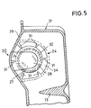
- Figure 5 shows a view from below into the valve housing 24 the Feinmeßhunt 11 out.
- The are radially arranged rib-shaped guide elements 31 recognizable, of which here six are provided. These guide elements hold the Valve plate 30 coincides with that of valve seat 27 enclosed valve opening.
- the valve plate 30 is in FIG. 5 not shown in the exact middle position, but on the side transferred. In any case, it covers the valve opening Completely. From Figure 5 it can also be seen that the Cantilever 28 only a part of the surface of the valve plate 30 reaches under. Towering over an angular range of more than 270 ° the valve plate 30 the contour of the cantilever arm 28.
- the intermediate wall 25 projects Is part of the rear housing part 21, in a groove 33, which are provided on the inside of the front wall 29 is. All guide elements 31 are part of the rear housing part 21.
- valve chamber 34 enclosed by the valve housing 24, in which protrude the guide elements 31 radially has one Diameter that is significantly larger than that Valve plate 30. Therefore, in that shown in Figure 3 State in which the valve plate 30 by its weight on the Cantilever arm 28 rests, liquid along the valve plate 30 and between the guide elements 31 into the precision measuring chamber 11 flow.
Landscapes
- Health & Medical Sciences (AREA)
- Life Sciences & Earth Sciences (AREA)
- Medical Informatics (AREA)
- Molecular Biology (AREA)
- Urology & Nephrology (AREA)
- Biophysics (AREA)
- Pathology (AREA)
- Engineering & Computer Science (AREA)
- Biomedical Technology (AREA)
- Heart & Thoracic Surgery (AREA)
- Physiology (AREA)
- Physics & Mathematics (AREA)
- Surgery (AREA)
- Animal Behavior & Ethology (AREA)
- General Health & Medical Sciences (AREA)
- Public Health (AREA)
- Veterinary Medicine (AREA)
- Investigating Or Analysing Biological Materials (AREA)
- Orthopedics, Nursing, And Contraception (AREA)
- Steroid Compounds (AREA)
- Investigating Or Analysing Materials By Optical Means (AREA)
Abstract
Description
- Fig. 1
- eine Vorderansicht des Urinmeßgerätes,
- Fig. 2
- einen Schnitt entlang der Linie II-II von Fig. 1,
- Fig. 3
- eine vergrößerte Darstellung des Ventilbereichs aus Fig. 2, wobei in der Sammelphase das Ventil geöffnet ist,
- Fig. 4
- in gleicher Darstellung wie Fig. 2 die Entleerungsphase, in der das Ventil geschlossen ist, und
- Fig. 5
- einen Schnitt entlang der Linie V-V von Fig. 2.
Claims (6)
- Urinmeßgerät mit einer Tropfkammer (15), in die ein Tropfer (18) mündet und die im Boden ein Ventil aufweist, wobei das Ventil aus einer Ventilöffnung (26), die an ihrer Unterseite einen umlaufenden Ventilsitz (27) aufweist, und einer Ventilplatte (30) besteht,
dadurch gekennzeichnet,
daß die Ventilplatte (30) ein frei bewegliches Losteil ist, das zwischen seitlichen Führungselementen (31) geführt ist. - Urinmeßgerät nach Anspruch 1, dadurch gekennzeichnet, daß die Ventilplatte (30) durch einen Kragarm (28) abgestützt ist.
- Urinmeßgerät nach Anspruch 1 oder 2, dadurch gekennzeichnet, daß die seitlichen Führungselemente (31) aus Rippen bestehen, die von der Wand eines Ventilgehäuses (24) nach innen abstehen, welches einen größeren Querschnitt hat als die Ventilöffnung (26).
- Urinmeßgerät nach einem der Ansprüche 1 bis 3, dadurch gekennzeichnet, daß das Ventil, mit Ausnahme der Ventilplatte (30), integraler Bestandteil eines Meßgeräte-Gehäuses (20,21) ist, das die Tropfkammer (15) enthält.
- Urinmeßgerät nach Anspruch 4, dadurch gekennzeichnet, daß das Meßgeräte-Gehäuse zwei zusammengesetzte Gehäuseteile (20;21) aufweist und daß die Ventilöffnung (26) und die Führungselemente (31) Bestandteil des einen Gehäuseteils (21) und ein die Ventilplatte (30) abstützender Kragarm (28) Bestandteil des anderen Gehäuseteils (20) sind.
- Urinmeßgerät nach einem der Ansprüche 1 bis 5, dadurch gekennzeichnet, daß die Querschnittsfläche der Ventilöffnung (26) um mindestens 70 % größer ist als der Innenquerschnitt des Tropfers (18).
Applications Claiming Priority (2)
| Application Number | Priority Date | Filing Date | Title |
|---|---|---|---|
| DE29820526U | 1998-11-17 | ||
| DE29820526U DE29820526U1 (de) | 1998-11-17 | 1998-11-17 | Urinmeßgerät |
Publications (2)
| Publication Number | Publication Date |
|---|---|
| EP1002507A1 true EP1002507A1 (de) | 2000-05-24 |
| EP1002507B1 EP1002507B1 (de) | 2003-02-19 |
Family
ID=8065438
Family Applications (1)
| Application Number | Title | Priority Date | Filing Date |
|---|---|---|---|
| EP99121233A Expired - Lifetime EP1002507B1 (de) | 1998-11-17 | 1999-10-23 | Urinmessgerät |
Country Status (5)
| Country | Link |
|---|---|
| US (1) | US6348046B2 (de) |
| EP (1) | EP1002507B1 (de) |
| AT (1) | ATE232706T1 (de) |
| DE (2) | DE29820526U1 (de) |
| ES (1) | ES2188085T3 (de) |
Families Citing this family (6)
| Publication number | Priority date | Publication date | Assignee | Title |
|---|---|---|---|---|
| WO2008038142A2 (en) * | 2006-09-28 | 2008-04-03 | Pan, Fei | Draining device |
| US8357105B2 (en) * | 2008-08-07 | 2013-01-22 | Covidien Lp | Anti-reflux mechanism for urine collection systems |
| US20120036926A1 (en) * | 2009-02-09 | 2012-02-16 | Pulsion Medical Systems Ag | Device and method for continuously measuring the flow velocity and total volume of a fluid, in particular of urine |
| ES2443078T3 (es) * | 2011-05-23 | 2014-02-17 | Covidien Lp | Urinómetro |
| CN205084081U (zh) * | 2014-11-24 | 2016-03-16 | 胡绍勤 | 一种自动排液引流装置 |
| US20230341975A1 (en) | 2022-04-20 | 2023-10-26 | Apple Inc. | Electronic Devices Having Moisture-Insensitive Optical Touch Sensors |
Citations (5)
| Publication number | Priority date | Publication date | Assignee | Title |
|---|---|---|---|---|
| US3928875A (en) * | 1973-02-20 | 1975-12-30 | Sture Ivan Persson | Throw-away receptacle for collection of urine of those confined to bed |
| DE2543778C3 (de) | 1974-10-02 | 1981-02-19 | The Kendall Co., Walpole, Mass. (V.St.A.) | Urinsammelbeutel mit einem auf seiner Innenseite vor einer Einlaßöffnung angeordneten Klappenventil |
| US4334537A (en) | 1981-01-28 | 1982-06-15 | The Kendall Company | Drainage receptacle with anti-reflux valve |
| US4490144A (en) * | 1983-02-10 | 1984-12-25 | The Kendall Company | Urine drainage receptacle with a normally open reflux valve |
| US4846816A (en) * | 1982-12-06 | 1989-07-11 | Manfredi Frank A | Male urinary drain system |
Family Cites Families (14)
| Publication number | Priority date | Publication date | Assignee | Title |
|---|---|---|---|---|
| US3604420A (en) * | 1969-01-21 | 1971-09-14 | Bard Inc C R | Closed system drainage design |
| US3583401A (en) * | 1969-01-21 | 1971-06-08 | Bard Inc C R | Vented closed drainage system with double lumen tube |
| US3831453A (en) * | 1972-02-10 | 1974-08-27 | Kendall & Co | Urine meter and collection receptacle |
| US3968925A (en) * | 1975-05-12 | 1976-07-13 | Plastronics, Inc. | Anti-reflux valve |
| US4158362A (en) * | 1977-08-23 | 1979-06-19 | Abbott Laboratories | Unidirectionally valved drip chamber, inlet port assembly useful for liquid collection containers |
| US4354492A (en) * | 1979-04-16 | 1982-10-19 | American Hospital Supply Corporation | Medical administration set with backflow check valve |
| FR2527452A1 (fr) * | 1982-06-01 | 1983-12-02 | Urologic Enteric Res Ass | Tube souple d'evacuation et recipient collecteur d'urine |
| US4615693A (en) * | 1984-03-27 | 1986-10-07 | Nypro Inc. | Administration of fluids |
| SE446656B (sv) * | 1985-01-08 | 1986-09-29 | Astra Meditec Ab | Ventilforsedd kopplingsanordning |
| US4743236A (en) * | 1985-05-17 | 1988-05-10 | Plastronics, Inc. | Combination urine meter and urinary drainage bag and the method of use |
| DK158130C (da) * | 1987-11-30 | 1990-09-03 | Uno Plast As | Apparat til opsamling og maaling af legemsvaeske |
| DE4137074A1 (de) * | 1991-11-12 | 1993-05-13 | Hessberg Sigfried Dipl Ing | Messzelle fuer ein geraet zur ueberwachung von aus einem katheter austretender koerperfluessigkeit |
| US5409014A (en) * | 1993-08-13 | 1995-04-25 | Dravon Medical, Inc. | Fluid meter |
| US6254581B1 (en) * | 1998-09-18 | 2001-07-03 | Creighton University | Pleural cavity drainage device |
-
1998
- 1998-11-17 DE DE29820526U patent/DE29820526U1/de not_active Expired - Lifetime
-
1999
- 1999-10-23 ES ES99121233T patent/ES2188085T3/es not_active Expired - Lifetime
- 1999-10-23 EP EP99121233A patent/EP1002507B1/de not_active Expired - Lifetime
- 1999-10-23 DE DE59904318T patent/DE59904318D1/de not_active Expired - Lifetime
- 1999-10-23 AT AT99121233T patent/ATE232706T1/de not_active IP Right Cessation
- 1999-11-03 US US09/432,227 patent/US6348046B2/en not_active Expired - Fee Related
Patent Citations (5)
| Publication number | Priority date | Publication date | Assignee | Title |
|---|---|---|---|---|
| US3928875A (en) * | 1973-02-20 | 1975-12-30 | Sture Ivan Persson | Throw-away receptacle for collection of urine of those confined to bed |
| DE2543778C3 (de) | 1974-10-02 | 1981-02-19 | The Kendall Co., Walpole, Mass. (V.St.A.) | Urinsammelbeutel mit einem auf seiner Innenseite vor einer Einlaßöffnung angeordneten Klappenventil |
| US4334537A (en) | 1981-01-28 | 1982-06-15 | The Kendall Company | Drainage receptacle with anti-reflux valve |
| US4846816A (en) * | 1982-12-06 | 1989-07-11 | Manfredi Frank A | Male urinary drain system |
| US4490144A (en) * | 1983-02-10 | 1984-12-25 | The Kendall Company | Urine drainage receptacle with a normally open reflux valve |
Also Published As
| Publication number | Publication date |
|---|---|
| US6348046B2 (en) | 2002-02-19 |
| EP1002507B1 (de) | 2003-02-19 |
| DE59904318D1 (de) | 2003-03-27 |
| ATE232706T1 (de) | 2003-03-15 |
| US20010016718A1 (en) | 2001-08-23 |
| ES2188085T3 (es) | 2003-06-16 |
| DE29820526U1 (de) | 2000-04-06 |
Similar Documents
| Publication | Publication Date | Title |
|---|---|---|
| DE2543778C3 (de) | Urinsammelbeutel mit einem auf seiner Innenseite vor einer Einlaßöffnung angeordneten Klappenventil | |
| WO2013177716A1 (de) | Drainagebehältervorrichtung und saugbeuteleinheit | |
| DE2945379A1 (de) | Vorrichtung zur abfuehrung von fluida aus einer wunde | |
| DE1491739B1 (de) | Vorrichtung zum Ableiten von Fluessigkeiten aus Koerperhohlraeumen | |
| DE3032143A1 (de) | Saug- und sammelvorrichtung fuer eine harnabsaugvorrichtung | |
| DE2103187B2 (de) | Medizinische Wegwerfvorrichtung zum Absaugen von Flüssigkeiten | |
| DE2438154A1 (de) | Geschlossene harnsammel- und -messanordnung | |
| DE3733810A1 (de) | Blutentnahmeventil | |
| EP1002507B1 (de) | Urinmessgerät | |
| DD248505A1 (de) | Ablasshahn fuer fluessigkeitsbehaelter | |
| DE69911929T2 (de) | Ventilsystem für Sammelbeutel | |
| DE202004008972U1 (de) | Staubfilterbeutel | |
| EP0058829B1 (de) | Tropfkammer in einem Ableitungssystem für Körpersekret, insbesondere Urin | |
| EP0042499B1 (de) | Flexibel ausgebildeter, einteiliger Auffangbehälter für medizinische Zwecke | |
| DE2637273B2 (de) | Vorrichtung zum Trennen von Blutfraktionen | |
| EP2467047B1 (de) | Vorrichtung zur absaugung von pulver- oder staubförmigem material | |
| DE102004054496B4 (de) | Drainagekammer zur Aufnahme von Körperfluiden, insbesondere von Liquor | |
| DE3126581C2 (de) | ||
| EP1725196B1 (de) | Drainagebeutel | |
| DE431949C (de) | Monatsbinde | |
| DE4318633A1 (de) | Anschlußvorrichtung für ein Urindrainagesystem | |
| DE2233841A1 (de) | Hahn fuer eine fluessigkeitsdruckmessanlage | |
| EP1872751A2 (de) | Harnauffangbeutel | |
| DE19720933C2 (de) | Geschlossenes Urin-Drainagesystem mit wiederverwendbarem Urinauffangbehälter | |
| DE102011104514A1 (de) | Selbstschließender Ausgießer |
Legal Events
| Date | Code | Title | Description |
|---|---|---|---|
| PUAI | Public reference made under article 153(3) epc to a published international application that has entered the european phase |
Free format text: ORIGINAL CODE: 0009012 |
|
| AK | Designated contracting states |
Kind code of ref document: A1 Designated state(s): AT BE CH CY DE DK ES FI FR GB GR IE IT LI LU MC NL PT SE |
|
| AX | Request for extension of the european patent |
Free format text: AL;LT;LV;MK;RO;SI |
|
| 17P | Request for examination filed |
Effective date: 20000707 |
|
| AKX | Designation fees paid |
Free format text: AT BE CH CY DE DK ES FI FR GB GR IE IT LI LU MC NL PT SE |
|
| 17Q | First examination report despatched |
Effective date: 20011008 |
|
| GRAG | Despatch of communication of intention to grant |
Free format text: ORIGINAL CODE: EPIDOS AGRA |
|
| GRAG | Despatch of communication of intention to grant |
Free format text: ORIGINAL CODE: EPIDOS AGRA |
|
| GRAH | Despatch of communication of intention to grant a patent |
Free format text: ORIGINAL CODE: EPIDOS IGRA |
|
| GRAH | Despatch of communication of intention to grant a patent |
Free format text: ORIGINAL CODE: EPIDOS IGRA |
|
| GRAA | (expected) grant |
Free format text: ORIGINAL CODE: 0009210 |
|
| AK | Designated contracting states |
Designated state(s): AT BE CH CY DE DK ES FI FR GB GR IE IT LI LU MC NL PT SE |
|
| PG25 | Lapsed in a contracting state [announced via postgrant information from national office to epo] |
Ref country code: NL Free format text: LAPSE BECAUSE OF FAILURE TO SUBMIT A TRANSLATION OF THE DESCRIPTION OR TO PAY THE FEE WITHIN THE PRESCRIBED TIME-LIMIT Effective date: 20030219 Ref country code: IE Free format text: LAPSE BECAUSE OF FAILURE TO SUBMIT A TRANSLATION OF THE DESCRIPTION OR TO PAY THE FEE WITHIN THE PRESCRIBED TIME-LIMIT Effective date: 20030219 Ref country code: GR Free format text: LAPSE BECAUSE OF FAILURE TO SUBMIT A TRANSLATION OF THE DESCRIPTION OR TO PAY THE FEE WITHIN THE PRESCRIBED TIME-LIMIT Effective date: 20030219 Ref country code: FI Free format text: LAPSE BECAUSE OF FAILURE TO SUBMIT A TRANSLATION OF THE DESCRIPTION OR TO PAY THE FEE WITHIN THE PRESCRIBED TIME-LIMIT Effective date: 20030219 |
|
| REG | Reference to a national code |
Ref country code: CH Ref legal event code: EP |
|
| REG | Reference to a national code |
Ref country code: IE Ref legal event code: FG4D Free format text: GERMAN |
|
| REF | Corresponds to: |
Ref document number: 59904318 Country of ref document: DE Date of ref document: 20030327 Kind code of ref document: P |
|
| PG25 | Lapsed in a contracting state [announced via postgrant information from national office to epo] |
Ref country code: SE Free format text: LAPSE BECAUSE OF FAILURE TO SUBMIT A TRANSLATION OF THE DESCRIPTION OR TO PAY THE FEE WITHIN THE PRESCRIBED TIME-LIMIT Effective date: 20030519 Ref country code: PT Free format text: LAPSE BECAUSE OF FAILURE TO SUBMIT A TRANSLATION OF THE DESCRIPTION OR TO PAY THE FEE WITHIN THE PRESCRIBED TIME-LIMIT Effective date: 20030519 Ref country code: DK Free format text: LAPSE BECAUSE OF FAILURE TO SUBMIT A TRANSLATION OF THE DESCRIPTION OR TO PAY THE FEE WITHIN THE PRESCRIBED TIME-LIMIT Effective date: 20030519 |
|
| REG | Reference to a national code |
Ref country code: ES Ref legal event code: FG2A Ref document number: 2188085 Country of ref document: ES Kind code of ref document: T3 |
|
| GBT | Gb: translation of ep patent filed (gb section 77(6)(a)/1977) | ||
| ET | Fr: translation filed | ||
| NLV1 | Nl: lapsed or annulled due to failure to fulfill the requirements of art. 29p and 29m of the patents act | ||
| REG | Reference to a national code |
Ref country code: IE Ref legal event code: FD4D Ref document number: 1002507E Country of ref document: IE |
|
| PG25 | Lapsed in a contracting state [announced via postgrant information from national office to epo] |
Ref country code: LU Free format text: LAPSE BECAUSE OF NON-PAYMENT OF DUE FEES Effective date: 20031023 Ref country code: CY Free format text: LAPSE BECAUSE OF FAILURE TO SUBMIT A TRANSLATION OF THE DESCRIPTION OR TO PAY THE FEE WITHIN THE PRESCRIBED TIME-LIMIT Effective date: 20031023 Ref country code: AT Free format text: LAPSE BECAUSE OF NON-PAYMENT OF DUE FEES Effective date: 20031023 |
|
| PG25 | Lapsed in a contracting state [announced via postgrant information from national office to epo] |
Ref country code: MC Free format text: LAPSE BECAUSE OF NON-PAYMENT OF DUE FEES Effective date: 20031031 Ref country code: LI Free format text: LAPSE BECAUSE OF NON-PAYMENT OF DUE FEES Effective date: 20031031 Ref country code: CH Free format text: LAPSE BECAUSE OF NON-PAYMENT OF DUE FEES Effective date: 20031031 Ref country code: BE Free format text: LAPSE BECAUSE OF NON-PAYMENT OF DUE FEES Effective date: 20031031 |
|
| PLBE | No opposition filed within time limit |
Free format text: ORIGINAL CODE: 0009261 |
|
| STAA | Information on the status of an ep patent application or granted ep patent |
Free format text: STATUS: NO OPPOSITION FILED WITHIN TIME LIMIT |
|
| 26N | No opposition filed |
Effective date: 20031120 |
|
| BERE | Be: lapsed |
Owner name: B. *BRAUN MELSUNGEN A.G. Effective date: 20031031 |
|
| REG | Reference to a national code |
Ref country code: CH Ref legal event code: PL |
|
| REG | Reference to a national code |
Ref country code: FR Ref legal event code: PLFP Year of fee payment: 17 |
|
| REG | Reference to a national code |
Ref country code: FR Ref legal event code: PLFP Year of fee payment: 18 |
|
| REG | Reference to a national code |
Ref country code: FR Ref legal event code: PLFP Year of fee payment: 19 |
|
| REG | Reference to a national code |
Ref country code: FR Ref legal event code: PLFP Year of fee payment: 20 |
|
| PGFP | Annual fee paid to national office [announced via postgrant information from national office to epo] |
Ref country code: DE Payment date: 20181024 Year of fee payment: 20 |
|
| PGFP | Annual fee paid to national office [announced via postgrant information from national office to epo] |
Ref country code: FR Payment date: 20181023 Year of fee payment: 20 Ref country code: GB Payment date: 20181025 Year of fee payment: 20 Ref country code: IT Payment date: 20181022 Year of fee payment: 20 Ref country code: ES Payment date: 20181122 Year of fee payment: 20 |
|
| REG | Reference to a national code |
Ref country code: DE Ref legal event code: R071 Ref document number: 59904318 Country of ref document: DE |
|
| REG | Reference to a national code |
Ref country code: GB Ref legal event code: PE20 Expiry date: 20191022 |
|
| PG25 | Lapsed in a contracting state [announced via postgrant information from national office to epo] |
Ref country code: GB Free format text: LAPSE BECAUSE OF EXPIRATION OF PROTECTION Effective date: 20191022 |
|
| REG | Reference to a national code |
Ref country code: ES Ref legal event code: FD2A Effective date: 20200723 |
|
| PG25 | Lapsed in a contracting state [announced via postgrant information from national office to epo] |
Ref country code: ES Free format text: LAPSE BECAUSE OF EXPIRATION OF PROTECTION Effective date: 20191024 |