EP1001707B1 - Vaso-okklusive anordnung - Google Patents
Vaso-okklusive anordnung Download PDFInfo
- Publication number
- EP1001707B1 EP1001707B1 EP98939234A EP98939234A EP1001707B1 EP 1001707 B1 EP1001707 B1 EP 1001707B1 EP 98939234 A EP98939234 A EP 98939234A EP 98939234 A EP98939234 A EP 98939234A EP 1001707 B1 EP1001707 B1 EP 1001707B1
- Authority
- EP
- European Patent Office
- Prior art keywords
- vaso
- occlusive
- aneurysm
- retainer
- delivery member
- Prior art date
- Legal status (The legal status is an assumption and is not a legal conclusion. Google has not performed a legal analysis and makes no representation as to the accuracy of the status listed.)
- Expired - Lifetime
Links
Images


Classifications
-
- A—HUMAN NECESSITIES
- A61—MEDICAL OR VETERINARY SCIENCE; HYGIENE
- A61B—DIAGNOSIS; SURGERY; IDENTIFICATION
- A61B17/00—Surgical instruments, devices or methods, e.g. tourniquets
- A61B17/12—Surgical instruments, devices or methods, e.g. tourniquets for ligaturing or otherwise compressing tubular parts of the body, e.g. blood vessels, umbilical cord
- A61B17/12022—Occluding by internal devices, e.g. balloons or releasable wires
- A61B17/12099—Occluding by internal devices, e.g. balloons or releasable wires characterised by the location of the occluder
- A61B17/12109—Occluding by internal devices, e.g. balloons or releasable wires characterised by the location of the occluder in a blood vessel
- A61B17/12113—Occluding by internal devices, e.g. balloons or releasable wires characterised by the location of the occluder in a blood vessel within an aneurysm
-
- A—HUMAN NECESSITIES
- A61—MEDICAL OR VETERINARY SCIENCE; HYGIENE
- A61B—DIAGNOSIS; SURGERY; IDENTIFICATION
- A61B17/00—Surgical instruments, devices or methods, e.g. tourniquets
- A61B17/12—Surgical instruments, devices or methods, e.g. tourniquets for ligaturing or otherwise compressing tubular parts of the body, e.g. blood vessels, umbilical cord
- A61B17/12022—Occluding by internal devices, e.g. balloons or releasable wires
- A61B17/12131—Occluding by internal devices, e.g. balloons or releasable wires characterised by the type of occluding device
- A61B17/1214—Coils or wires
-
- A—HUMAN NECESSITIES
- A61—MEDICAL OR VETERINARY SCIENCE; HYGIENE
- A61B—DIAGNOSIS; SURGERY; IDENTIFICATION
- A61B17/00—Surgical instruments, devices or methods, e.g. tourniquets
- A61B17/12—Surgical instruments, devices or methods, e.g. tourniquets for ligaturing or otherwise compressing tubular parts of the body, e.g. blood vessels, umbilical cord
- A61B17/12022—Occluding by internal devices, e.g. balloons or releasable wires
- A61B17/12131—Occluding by internal devices, e.g. balloons or releasable wires characterised by the type of occluding device
- A61B17/12168—Occluding by internal devices, e.g. balloons or releasable wires characterised by the type of occluding device having a mesh structure
- A61B17/12172—Occluding by internal devices, e.g. balloons or releasable wires characterised by the type of occluding device having a mesh structure having a pre-set deployed three-dimensional shape
-
- A—HUMAN NECESSITIES
- A61—MEDICAL OR VETERINARY SCIENCE; HYGIENE
- A61B—DIAGNOSIS; SURGERY; IDENTIFICATION
- A61B17/00—Surgical instruments, devices or methods, e.g. tourniquets
- A61B17/12—Surgical instruments, devices or methods, e.g. tourniquets for ligaturing or otherwise compressing tubular parts of the body, e.g. blood vessels, umbilical cord
- A61B17/12022—Occluding by internal devices, e.g. balloons or releasable wires
- A61B2017/1205—Introduction devices
- A61B2017/12054—Details concerning the detachment of the occluding device from the introduction device
- A61B2017/12063—Details concerning the detachment of the occluding device from the introduction device electrolytically detachable
Definitions
- This invention is a device for bridging the neck of either a wide-necked or narrow-necked aneurysm in the vasculature and stabilizing the presence of vaso-occlusive devices (such as helically wound coils) in that aneurysm.
- the retainer assembly may be delivered from its attachment to the distal end of a tubular member preferably by the severance of an included electrolytically severable joint.
- the retainer assembly itself typically has a number of array elements which are intended to be resident within the aneurysm after the device is deployed from the distal end of a catheter. After deployment of this retainer, the aneurysm is at least partially filled with a vaso-occlusive device such as helically wound coils.
- occlusive devices are useful in filling vascular or other body spaces.
- Some body spaces, such as vascular aneurysms, are formed due to a weakening in the wall of an artery. Often these aneurysms are the site of internal bleeding and stroke.
- embolic agents are known as, at least ideally, suitable for treatment of these anomalies. These treatments are commonly known as “artificial vaso-occlusion.”
- embolic agents includes indictable fluids or suspensions, such as microfibrillar collagen, various polymeric beads, and polyvinylalcohol foam. These polymeric agents may additionally be crosslinked, sometimes in vivo, to extend the persistence of the agent at the vascular site. These agents are often introduced into the vasculature through a catheter. After such introduction, the introduced materials there form a solid space-filling mass. Although some provide excellent short term occlusion, many are thought to allow vessel recanalization due to absorption of polymer into the blood. Another procedure in which a partially hydrolyzed polyvinylacetate (PVA) is dissolved in an ethanol solvent and ejected into a desired vascular site is found in US-A-5,925,683. Other materials such as hog hair and suspensions of metal particles have also been suggested and used by those wishing to form occlusions.
- PVA polyvinylacetate
- Other materials including polymer resins, typically cyanoacrylates, are also employed as injectable vaso-occlusive materials. These resins are typically mixed with a radio-opaque contrast material or are made radio-opaque by the addition of a tantalum powder. Their use is fraught with problems in that placement of the mixture is quite difficult. These materials may crosslink with the human body. Inadvertent embolisms in normal vasculature (due to the inability of controlling the destination of the resins) is not uncommon. The material is also difficult or impossible to retrieve once it has been placed in the vasculature.
- vaso-occlusive devices Implantable metal coils that are useful as artificial occlusion devices in vasculature lumens or aneurysms are herein referred to as "vaso-occlusions coils.”
- Vaso-occlusion coils are generally constructed of a wire, usually made of a metal or metal alloy, that is wound to a helix. Many such devices are introduced to the selected target site through a catheter in a stretched linear form. The vaso-occlusive device assumes an irregular shape upon discharge of the device from the distal end of the catheter a variety of vaso-occlusive coils and braids are known. For instance, U.S. Patent No. 4, 994,069, to Ritchart et al. shows a flexible, preferably coiled, wire for use in small vessel vaso-occlusion.
- Ritchart et al taught a coil which is fairly soft and is delivered to the site using a pusher within a catheter lumen. Upon discharge from the delivery catheter, the coil may undertake any of the number of random or regular configurations used to fill the site.
- the coils may be used for small vessel sites, e.g., 0.5-6 mm in diameter.
- the coils themselves are described as being between 0.0254 and 0.0762 cm (010 and 0.030 inches) in diameter.
- the length of the coil wire is typically 15 to 20 times the diameter of the vessel to be occluded.
- the wire used to make up the coils may be, for instance, 0.0051 to 0.0152 cm (0.002 to 0.006 inches) in diameter.
- Tungsten, platinum, and gold threads or wires are said to be preferred. These coils have a variety of benefits including the fact that they are relatively permanent, they may be easily imaged radiographically, they may be located at a well defined vessel site, and they can be retrieved.
- vaso-occlusive devices be delivered through microcatheters such as the type disclosed in U.S. Patent No. 4,739,768, to Engelson. These microcatheters track a guidewire to a point just proximal or within the desired site for occlusion. The coil is advanced through the microcatheter (once the guidewire is removed) and out the distal end hole so to at least partially fill the selected space and create an occlusion.
- vaso-occlusive coils In addition to vaso-occlusion devices or coils having predetermined secondary shapes that dictate in part their space filling mechanism, other vaso-occlusive coils have been disclosed that take on random shapes when expelled from a delivery sheath.
- a vaso-occlusive coil often referred to as "a liquid coil”.
- a liquid coil is a very soft and flexible coil which is flow-injectable through a delivery catheter using, e.g., saline solution.
- vaso-occlusive coils In addition to the various types of space filling mechanisms and geometries of vaso-occlusive coils, other particularized features of coil designs, such as mechanisms for delivering vaso-occlusive coils through delivery catheters and implanting them in a desired occlusion site, have also been described.
- the examples of categories of vaso-occlusive coils based upon their delivery mechanisms include pushable coils, mechanically detachable coils, and electrolytically detachable coils.
- Pushable coils are commonly provided in a cartridge and are pushed or “plunged” from the cartridge into a delivery catheter lumen pusher advances the pushable coil through and out of the delivery catheter lumen and into the site for occlusion.
- Mechanically detachable vaso-occlusive devices are typically integrated with a pusher rod and are mechanically detached from the distal end of that pusher after exiting a delivery catheter. Examples of such mechanically detachable vaso-occlusive coils are found in U.S. Patent No. 5,261,916 to Engelson or U.S.. Patent No. 5,250,071 to Palermo.
- vaso-occlusive coils having fibers attached thereto are known -- see, for example, U.S. Patent No. 5,226,911, to Chee et al.
- Each of the devices described above may be used in the treatment by occlusion of aneurysms.
- aneurysms present particularly acute medical risk due to the dangers of potential rupture of the thin wall inherent in such aneurysm.
- Occlusion of aneurysms by use of vaso-occlusive coils without occluding the adjacent artery is a special challenge and is a desirable method of reducing such risk of rupture.
- vaso-occlusive coils in treating aneurysms are widespread. These vaso-occlusive devices are placed in an aneurysm in the following fashion. A microcatheter is initially steered into or adjacent to the entrance of an aneurysm, typically aided by the use of a steerable guidewire. The wire is then withdrawn from the microcatheter lumen and replaced by the vaso-occlusive coil. The vaso-occlusive coil is advanced through and out of the microcatheter, desirably being completely delivered into the aneurysm.
- Aneurysm commonly known as a "wide neck aneurysm” is known to present particular difficulty in the placement and retention of vaso-occlusive coils.
- Wide neck aneurysms are herein referred to as aneurysms of vessel walls having a neck or a "entrance zone" from the adjacent vessel, which entrance zone has a diameter that either: (1) is at least 80% of the largest diameter of the aneurysm; or (2) is clinically observed to be too wide effectively to retain vaso-occlusive coils that are deployed using the techniques discussed above.
- vaso-occlusive coils lacking substantial secondary shape strength may be difficult to maintain in position within an aneurysm no matter how skillfully they are placed.
- EP-A-0 820 726 which is a European patent application that falls within the terms of Article 54(3) EPC. That application describes devices which are said to be placed within the lumen of a feed vessel exterior to the aneurysm so to retain coils within the aneurysm cavity. That is to say that the retainer device is released in the good vessel exterior to the aneurysm. The device is held in place via the use of radial pressure on the vessel wall.
- a microcatheter is inserted into the lumen behind the retainer device; the distal end of the catheter is inserted into the aneurysm cavity.
- One or more vaso-occlusive devices is introduced into the aneurysm cavity.
- the retainer device maintains the presence of those vaso-occlusive devices within the aneurysm no matter whether the aneurysm is a large mouth aneurysm or not.
- a vaso-occlusive device such as a coil or braid has on its outer surface a polymeric composition which may be reformed or solidified in situ within the human body.
- the device is simply inserted into the aneurysm and the polymer is then reformed, e.g., by the application of light to melt or otherwise reform the polymer exterior to the vaso-occlusive device.
- the vaso-occlusive device then sticks to itself at the various sites of self-contact and forms a rigid whole mass within the aneurysm.
- DE-U-9413645 discloses an implant configured to be placed in a duct connected between two vessels.
- the implant is made from a foam-like material that swells when contacted with liquid.
- US-A-5354295 discloses a vaso-occlusive device for occluding an aneurysm. The vaso-occlusive device is self-anchoring within the aneurysm.
- a vaso-occlusive system comprising:
- implantable medical device is useful for retaining occlusion devices at an occlusion site, such as an aneurysm.
- the implantable vaso-occlusive device retainer is deliverable through an elongated tubular delivery device such as a vascular catheter.
- the assemblage includes an implantable retainer which is placed in and allowed to remain in an aneurysm and a tubular delivery member to which it is attached by an electrolytically severable joint.
- the implantable retainer component may either extend from the distal end of the tubular delivery member or may include a small tubular section which in turn is slipped over the distal end of the delivery component.
- the joint itself is electrolytically severable upon application of a suitable current to the joint, typically by use of a conductor wire which may be placed in the wall of the delivery member.
- the joint is comparatively more electrolytically dissolvable when a current is applied than are any of the rest of the components which surround or deliver it.
- the retainer component itself has a number of array elements shaped preferably the general shape of flower petals in a flower.
- the array elements may either be exterior wires or regions having exterior wires and covered with a mesh of some kind.
- the petals or array elements have a primary shape when inside the delivery tubular member and then assume a secondary shape upon exit from the distal end of that delivery tubular member.
- the vaso-occlusive device e.g. vaso-occlusive coils
- the vaso-occlusive device may be introduced into the aneurysm either through the small tubular member to which the array members are attached or, if the array members do not have a mesh covering, through the open area found at the neck of the aneurysm.
- This invention relates to a device for stabilizing the position and, usually, the structure of vaso-occlusive devices which are placed in a target occlusion site, usually an aneurysm.
- the retaining devices prevent the potential migration of those one or more occlusive devices (e.g., helically wound coils) from that target occlusion site, by forming a barrier at the entrance zone to the aneurysm where it meets a feeding vessel.
- Figure 1 shows in partial cross section, the general assemblage of components used to deliver both the aneurysm neck bridge and the accompanying vaso-occlusive devices.
- a tubular delivery member (102) which may be vascular catheter designed for other purposes or more likely one specifically designed for this purpose.
- Interior to the delivery catheter or member (102) is an inner elongated tubular member (104), which is attached via an electrolytically severable joint to the aneurysm neck bridge (106).
- the severable joint is of a scale that cannot easily be seen in Figure 1 and is depicted in greater clarity in Figures 2A and 2B.
- a vaso-occlusive device in this case a helically wound coil (108), is interior to both of the tubular delivery members and it too is severable from its delivery member by an electrolytically severable joint which also is too small to be seen in this particular rendition.
- the core wire (110) to which it is attached may more clearly be seen at the proximal end of the overall assembly (100). It will be noted at proximal end of the delivery catheter (102) that a pair of power supplies are depicted. Schematically at least, a first power supply (112) is used to deliver current to the electrolytically severable joint, the severance of which releases the aneurysm neck bridge (106).
- a second power supply (114) is depicted as providing a current to sever the electrolytic joint attached to vaso-occlusive coil (108). It would not be typical that both power supplies are used at the same time and consequently a single power supply is likely adequate for both purposes obviously after having switched from one conductor to the other.
- the aneurysm neck bridge (106) is shown in Figures 1 and 2A in the so-called "secondary" shape or condition.
- the neck bridge or retainer (106) is delivered to the chosen site within the lumen of the delivery catheter (102). It is only after the retainer (106) is pushed from the distal end of the delivery catheter (102) that it unfolds to form the secondary shape shown in these two drawings. Obviously, prior to the time it is pushed from the safe harbor within the delivery catheter (102), it generally maintains the shape of the inner lumen of that catheter (102). Consequently, we describe the shape of the aneurysm retainer (106) as a "secondary shape" which is different from the "primary shape” or “delivery shape” it maintains during the time the neck bridge (106) is within the delivery catheter (102).
- Figure 2A is a close-up cross section of the distal tip of the assembly (100) shown in Figure 1.
- the distal tip of delivery catheter (102) may be seen with its radio-opaque marker (116).
- the inner tubular delivery member (104) may be seen in cross section.
- Inner delivery tubular member (104) is shown with two radio-opaque markers (118).
- Conductor (120) is for conducting current from first power supply (112) to electrolytically detachable joint (122).
- the construction of electrolytically severable joint (122) is shown in more detail elsewhere herein.
- Aneurysm neck bridge (106) is shown in this variation as having a small tubular member (124), the interior of which is slid onto the distal end of inner tubular delivery member (104).
- this small tubular member (124) is typically somewhat loose around the inner delivery member (104) and is maintained in position on that inner delivery member (104) by the electrolytic joint (122).
- retainer member (106) may be seen a number of array members or wires (126) which, upon placement in the aneurysm, spread to the general shape shown in Figure 2A.
- core wire (110) may be seen, along with its insulating layer (128).
- This insulating layer (128) allows the current flowing from second power supply (114) to pass without creating other circuits, to the electrolytically severable joint (130). Passage of current through electrolytically severable joint (130) and its ultimate severance from core wire (110) will release vaso-occlusive device (108) into the aneurysm. The sequence of operation of each of these devices will be apparent from the discussion below.
- Figure 2B shows an even greater magnification (also in cross section) of the most distal portion of inner tubular delivery member (104).
- the radio-opaque members (118) are also shown in Figure 2B.
- the small tubular member (124) forming the central portion of retainer member (106) may also be seen.
- a portion of array members (126) may also be seen in Figure 2B.
- Figure 3 shows a cross-sectional view of another variation of the inventive concept described herein.
- the major difference between the variation shown in Figure 3 and the variation shown in Figures 2A and 2B involves the manner in which the retainer or neck bridge is attached to the elongate tubular delivery member.
- FIG 3 again shows a delivery catheter (102) with its radio-opaque marker (116).
- the inner elongate delivery member (150) also has one or more radio-opaque markers (152) and conductive wire (154) which may be embedded in the member wall.
- the major difference from the previously described variations of the invention is that the aneurysm bridge or retainer subassembly (156), although attached with an electrolytically severable joint (158) to delivery member (150), is so attached without benefit of the short tubular member 124 (shown in Figures 2A and 2B). Instead, the electrolytic joint (158) fixedly attaches the retainer subassembly (156) to the distal end of delivery member (150).
- a simple pair of loops (160) are shown as making up aneurysm neck bridge or retainer (156) subassembly. This configuration or that shown in the drawings which follow may be used as desired.
- core wire (110) with its insulative coating (128) is shown also having an electrolytically severable joint (130) and a vaso-occlusive coil (108).
- the array elements or loops (126) in Figures 2A and 2B and (160) in Figure 3 and those discussed below, are required to undertake massive changes in shape during deployment in the human body.
- the various retainer subassembly elements be produced of a material such as a super-elastic alloy.
- super-elastic or pseudoelastic shape recovery alloys are well known in this art. For instance, U.S. Patent Nos. 3,174,851; 3,351,463; and 3,753,700 each describe one of the more well known super-elastic alloys, known as Nitinol.
- alloys are characterized by their ability to be transformed from an austenitic crystal structure to a stress-induced martensitic (SIM) structure at certain temperatures and then to return elastically to the austenitic shape when the stress is removed.
- SIM stress-induced martensitic
- These alternating crystal structures provide the alloy with its super-elastic properties.
- the alloy mentioned in the three patents just above, is a nickel titanium alloy. It is readily commercially available and undergoes the austenitic-SIM-austenitic transformation at a variety of temperatures between -20°C and +30°C.
- alloys are especially suitable because of their capacity to recover elastically, almost completely, to the initial configuration once the stress is removed.
- This ability allows the retainer device to undertake substantial bends both as it is collapsed to enter the various tubular delivery devices and as it undertakes further bending in passing through the vasculature. In spite of this bending, it returns to its original shape once the bend has been traversed without retaining kinks or permanent bends.
- the super-elastic alloys currently available, we consider our preferred material to be nominally 50.6 ⁇ 2% nickel with most of the remainder being titanium. Up to about 5% of the alloy may be a member of the iron group of metals, particularly chromium and iron. The alloy should not contain more than about 500 parts per million of oxygen, carbon, or nitrogen. The transition temperature of this material is not particularly important, but it should be reasonably below the typical temperature of the human body so to allow it to be in its austenitic phase during use. The diameter of the wires or ribbons making up the various array elements preferably are smaller than about 0.0254 cm (0.010 inches) in diameter. These super-elastic alloys are not always completely visible under fluoroscopy as it is used in the human body.
- Radio-opaque metals such as gold and platinum are well known. They may be added the various elements of this inventive device by such widely recognized methods as by plating or by wrapping the element in a radio-opaque wire or ribbon..
- the various array elements be of polymeric materials. Polymeric materials are somewhat easier to work with in forming a device. Such polymeric materials may include members from the group of polyethylene, polypropylene, polytetraflouroethylene, various Nylons, and the like. These polymers are easily chosen by one having ordinary skill in this art for the purposes shown herein.
- the various electrolytically severable joints may also be denominated as sacrificial links.
- the core wire (110) is typically coated with an electrical insulator which is not susceptible to dissolution via the electrolysis process in blood or other ionic media.
- Suitable coatings for core wires (110) includes such insulating materials as the polyfluorocarbons (e.g., Teflon), polyurethane, polyethylene, polypropylene, polyimides, or other suitable well known polymeric materials.
- the various electrolytically severable joints are not coated with such an insulator but they are made of materials which are susceptible to electrolytic dissolution in blood.
- electrolytically severable joints may be a simple uninsulated continuation of, e.g., the stainless steel core wire (110), which has been insulated proximally of the joint. It should also be apparent that the sacrificial joints are more susceptible to electrolysis than any of the other elements of the device near that joint. Further discussion of the construction of, placement of, and other physical details of such electrolytically severable joints may be found in U.S. Patent Nos. 5,122,136 to Guglielmi et al.; 5,354,295 to Guglielmi et al.; and 5,624,449 to Pham et al.; and others.
- FIGS 4A and 4B show respectively a side, top view of another variation (180) the inventive retainer.
- This retainer includes the small tubular member (182) which, after being placed in an aneurysm, is near the mouth of the aneurysm.
- This variation (180) has two array elements (184).
- Each of the portrayed array elements (184) includes an outer wire or ribbon rim (186) and a mesh filler (188).
- the mesh filler (188) may be a woven cloth, a flat woven mesh, a knitted mesh, or other common and non-critical sheetings.
- the rim material (186) is preferably of a form which retains a large measure of elasticity after having been bent, the filler or field material (188) need not be so elastic.
- the material making up sheeting (188) not have substantial strength so to allow the device to be folded and placed into the various delivery catheters and the like discussed above without adding unnecessary stiffness.
- the sole function of the sheeting (188) is simply to maintain the presence of the vaso-occlusive coils in the aneurysm. It is the rim material (186) of the array member (184) which is intended to maintain the structural integrity of the device as it is situated in the aneurysm.
- FIG. 5A and Figure 5B show respectively side and top views of aneurysm retainer subassemblies (190) made according to the invention.
- This variation (190) is similar to that shown in Figures 4A and 4B except that it has three array elements (192) rather than the two overlapping elements shown in Figures 4A and 4B.
- This configuration has the benefit of being somewhat more open and perhaps allowing easier access to the interior of the aneurysm for placement of vaso-occlusive materials including coils and chemical vaso-occlusive materials such as cyanoacrylates.
- Materials of construction in the variation shown in Figures 5A and 5B are the same as those utilized in Figures 4A and 4B.
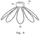
- Figure 6 shows another variation (196) of the inventive aneurysm retainer assembly. It too includes a small tubular member (198) which, as with variations discussed above, become situated at the mouth of the aneurysm, but preferably not in the feed vessel, and is the principal passageway for entry of vaso-occlusive devices into the aneurysm cavity.
- This variation of the invention includes a number of interior array elements (200).
- the array elements (200) are shown without the presence of a mesh or other covering in the loops of the array element (200). It is within the scope of this invention that array elements (200) and the analogous ones shown above may be used with or without mesh depending upon the shape of the aneurysm and the configuration of its opening into the feed vessel.
- array elements having mesh coverings would provide additional stability to the large mouth of an aneurysm and therefore the lessen the chance that vaso-occlusive device placed in the aneurysm will either enter the feed vessel or creep distally with blood flow.
- Figures 7A through 7E show the manner in which these devices are typically used in occluding and stabilizing an aneurysm.
- Figure 7A shows the placement of the distal end of a catheter (204) within the mouth of an aneurysm (206).
- Figure 7B shows catheter (204) having been withdrawn proximally a bit and the aneurysm retainer device (208) placed in the mouth of the aneurysm (206).
- the inner tubular delivery member (210) is shown with its electrolytic joint (212) still intact.
- Figure 7C shows the introduction of vaso-occlusive devices, in this case helically wound coils (214) into the vascular cavity interior to the retainer device (208).
- FIG 7D shows the vascular cavity of aneurysm (206) filled with coils (214) and the electrolytic joint maintaining the continuity between the core wire (shown in other drawings) severed.
- electrolytic joint (212) has been severed and the placement catheter (204) and the interior tubular delivery member (210) have withdrawn leaving the vaso-occlusive device (214) in place within aneurysm (206).
- the neck bridge or retainer (208) is shown stabilizing the presence of that coil (214) and preventing vaso-occlusive coil (214) from being drawn into the feed vessel.
- this variation of the invention shows that the small tubular member (216) is also placed well out of the normal blood flow of the feed vessel.
Claims (10)
- Vaso-Okklusiv-System, aufweisend:eine Vaso-Okklusiv-Wicklung (108, 214) zum Okkludieren eines Aneurysma's (206), undeine Rückhalte-Anordnung, welche ein längliches, rohrförmiges Zuführelement (104, 150, 210) und einen Vaso-Okklusiv-Vorrichtung-Rückhalter (106, 156, 180, 190, 196, 208) aufweist, wobei der Vaso-Okklusiv-Vorrichtung-Rückhalter eine Mehrzahl von Schleifen (126, 160, 186, 200) aufweist, welche an ein Distalende des länglichen, rohrförmigen Zuführelements gekuppelt sind, wobei der Rückhalter eine Zuführgestalt, wenn er innerhalb eines Gefäß-Katheters (102, 204) gehalten wird, und eine Entfaltungsgestalt aufweist, welche anders als die Zuführgestalt, wenn der Rückhalter nicht in dem Gefäß-Katheter gehalten wird, wobei der Vaso-Okklusiv-Vorrichtung-Rückhalter eine derartige Größe aufweist, dass er in das Aneurysma hinein zuführbar ist zum Zurückhalten der Vaso-Okklusiv-Wicklung innerhalb des Aneurysma's.
- Vaso-Okklusiv-System gemäß Anspruch 1, wobei die Mehrzahl von Schleifen (126, 160, 186, 200) aus einem Material aufgebaut ist, welche aus einer Gruppe ausgewählt ist, welche aus rostfreiem Stahl und superelastischen Legierungen zusammengesetzt ist.
- Vaso-Okklusiv-System gemäß einem der vorherigen Ansprüche, wobei die Mehrzahl von Schleifen (126, 160, 186, 200) zumindest teilweise mit einem Gewebe oder einem Netz (192) bedeckt sind.
- Vaso-Okklusiv-System gemäß einem der vorherigen Ansprüche, wobei die Mehrzahl von Schleifen (126, 160, 186, 200) strahlenundurchlässig sind.
- Vaso-Okklusiv-System gemäß einem der vorherigen Ansprüche, wobei das längliche, rohrförmige Zuführelement (104, 150, 210) zusätzlich mindestens eine strahlenundurchlässige Marke (118, 152) aufweist, welche distal angeordnet ist.
- Vaso-Okklusiv-System gemäß einem der vorherigen Ansprüche, ferner aufweisend:ein Vaso-Okklusiv-Vorrichtung-Zuführelement zum Zuführen der Vaso-Okklusiv-Wicklung (108, 214), wobei das Vaso-Okklusiv-Vorrichtung-Zuführelement einen Kerndraht (110) aufweist, welcher ein Proximalende und ein Distalende hat, wobei das Kerndraht-Distalende an der Vaso-Okklusiv-Wicklung über eine elektrolytisch trennbaren Verbindungsstelle (130) abtrennbar angebracht ist, welche nach Anlegung einer geeigneten Spannung abtrennbar ist.
- Vaso-Okklusiv-System gemäß einem der vorherigen Ansprüche; welches ferner den Gefäß-Katheter (102, 204) aufweist.
- Vaso-Okklusiv-System gemäß einem der vorherigen Ansprüche, wobei der Vaso-Okklusiv-Vorrichtung-Rückhalter ferner einen zentralen, rohrförmigen Abschnitt (124, 182, 198, 216) aufweist, wobei die Mehrzahl von Schleifen (126, 160, 186, 200) jeweilige Enden haben, welche an dem zentralen, rohrförmigen Anschnitt fest angebracht sind und wobei die Mehrzahl von Schleifen an das längliche, rohrförmige Zuführelement (104, 150, 210) über den zentralen rohrförmigen Abschnitt gekuppelt sind.
- Vaso-Okklusiv-System gemäß Anspruch 8, wobei der zentrale rohrförmige Abschnitt (124, 182, 198, 216) an das rohrförmige Zuführelement (104, 150, 210) über eine elektrolytisch trennbare Verbindungsstelle (122) angebracht ist.
- Vaso-Okklusiv-System gemäß einem der Ansprüche 1-7, wobei die Mehrzahl von Schleifen (126, 160, 186, 200) an das Distalende des länglichen, rohrförmigen Zuführelements (104, 150, 210) über eine elektrolytisch abtrennbare Verbindungsstelle direkt angebracht sind.
Applications Claiming Priority (5)
| Application Number | Priority Date | Filing Date | Title |
|---|---|---|---|
| US5476897P | 1997-08-05 | 1997-08-05 | |
| US54768 | 1997-08-05 | ||
| US126700 | 1998-07-30 | ||
| US09/126,700 US6063070A (en) | 1997-08-05 | 1998-07-30 | Detachable aneurysm neck bridge (II) |
| PCT/US1998/016308 WO1999007294A1 (en) | 1997-08-05 | 1998-08-04 | Detachable aneurysm neck bridge (ii) |
Publications (2)
| Publication Number | Publication Date |
|---|---|
| EP1001707A1 EP1001707A1 (de) | 2000-05-24 |
| EP1001707B1 true EP1001707B1 (de) | 2006-03-08 |
Family
ID=26733472
Family Applications (1)
| Application Number | Title | Priority Date | Filing Date |
|---|---|---|---|
| EP98939234A Expired - Lifetime EP1001707B1 (de) | 1997-08-05 | 1998-08-04 | Vaso-okklusive anordnung |
Country Status (7)
| Country | Link |
|---|---|
| US (2) | US6063070A (de) |
| EP (1) | EP1001707B1 (de) |
| JP (1) | JP4057776B2 (de) |
| AU (1) | AU8770598A (de) |
| CA (1) | CA2299350C (de) |
| DE (1) | DE69833767T2 (de) |
| WO (1) | WO1999007294A1 (de) |
Cited By (1)
| Publication number | Priority date | Publication date | Assignee | Title |
|---|---|---|---|---|
| EP4147652A1 (de) * | 2016-02-10 | 2023-03-15 | Microvention, Inc. | Vorrichtungen für gefässverschluss |
Families Citing this family (290)
| Publication number | Priority date | Publication date | Assignee | Title |
|---|---|---|---|---|
| US5928260A (en) * | 1997-07-10 | 1999-07-27 | Scimed Life Systems, Inc. | Removable occlusion system for aneurysm neck |
| US7569066B2 (en) | 1997-07-10 | 2009-08-04 | Boston Scientific Scimed, Inc. | Methods and devices for the treatment of aneurysms |
| US6168615B1 (en) | 1998-05-04 | 2001-01-02 | Micrus Corporation | Method and apparatus for occlusion and reinforcement of aneurysms |
| US6641593B1 (en) | 1998-06-03 | 2003-11-04 | Coalescent Surgical, Inc. | Tissue connector apparatus and methods |
| US6613059B2 (en) | 1999-03-01 | 2003-09-02 | Coalescent Surgical, Inc. | Tissue connector apparatus and methods |
| US6945980B2 (en) | 1998-06-03 | 2005-09-20 | Medtronic, Inc. | Multiple loop tissue connector apparatus and methods |
| US5935148A (en) * | 1998-06-24 | 1999-08-10 | Target Therapeutics, Inc. | Detachable, varying flexibility, aneurysm neck bridge |
| US6165193A (en) * | 1998-07-06 | 2000-12-26 | Microvention, Inc. | Vascular embolization with an expansible implant |
| EP1109499B1 (de) * | 1998-09-04 | 2007-08-15 | Boston Scientific Limited | Ablösbares system zum verschliessen eines aneurysmashalses |
| US7410482B2 (en) | 1998-09-04 | 2008-08-12 | Boston Scientific-Scimed, Inc. | Detachable aneurysm neck bridge |
| US7044134B2 (en) * | 1999-11-08 | 2006-05-16 | Ev3 Sunnyvale, Inc | Method of implanting a device in the left atrial appendage |
| US7128073B1 (en) * | 1998-11-06 | 2006-10-31 | Ev3 Endovascular, Inc. | Method and device for left atrial appendage occlusion |
| US7713282B2 (en) * | 1998-11-06 | 2010-05-11 | Atritech, Inc. | Detachable atrial appendage occlusion balloon |
| US6569179B2 (en) | 1998-11-10 | 2003-05-27 | Scimed Life Systems, Inc. | Bioactive three loop coil |
| US6723112B2 (en) | 1998-11-10 | 2004-04-20 | Scimed Life Systems, Inc. | Bioactive three loop coil |
| US8016852B2 (en) | 1998-11-10 | 2011-09-13 | Stryker Corporation | Bioactive components for incorporation with vaso-occlusive members |
| CA2351531C (en) * | 1998-11-18 | 2007-04-24 | General Surgical Innovations, Inc. | Helical fastener and applicator for surgical procedures |
| US8118822B2 (en) | 1999-03-01 | 2012-02-21 | Medtronic, Inc. | Bridge clip tissue connector apparatus and methods |
| US6695859B1 (en) * | 1999-04-05 | 2004-02-24 | Coalescent Surgical, Inc. | Apparatus and methods for anastomosis |
| US6375668B1 (en) | 1999-06-02 | 2002-04-23 | Hanson S. Gifford | Devices and methods for treating vascular malformations |
| US20020169473A1 (en) | 1999-06-02 | 2002-11-14 | Concentric Medical, Inc. | Devices and methods for treating vascular malformations |
| US8529583B1 (en) | 1999-09-03 | 2013-09-10 | Medtronic, Inc. | Surgical clip removal apparatus |
| US6231561B1 (en) | 1999-09-20 | 2001-05-15 | Appriva Medical, Inc. | Method and apparatus for closing a body lumen |
| US6689150B1 (en) * | 1999-10-27 | 2004-02-10 | Atritech, Inc. | Filter apparatus for ostium of left atrial appendage |
| US6551303B1 (en) * | 1999-10-27 | 2003-04-22 | Atritech, Inc. | Barrier device for ostium of left atrial appendage |
| US6652555B1 (en) * | 1999-10-27 | 2003-11-25 | Atritech, Inc. | Barrier device for covering the ostium of left atrial appendage |
| US6926730B1 (en) | 2000-10-10 | 2005-08-09 | Medtronic, Inc. | Minimally invasive valve repair procedure and apparatus |
| US6994092B2 (en) * | 1999-11-08 | 2006-02-07 | Ev3 Sunnyvale, Inc. | Device for containing embolic material in the LAA having a plurality of tissue retention structures |
| US6790218B2 (en) | 1999-12-23 | 2004-09-14 | Swaminathan Jayaraman | Occlusive coil manufacture and delivery |
| US20050187564A1 (en) * | 1999-12-23 | 2005-08-25 | Swaminathan Jayaraman | Occlusive coil manufacturing and delivery |
| US6551332B1 (en) | 2000-03-31 | 2003-04-22 | Coalescent Surgical, Inc. | Multiple bias surgical fastener |
| US6730104B1 (en) | 2000-06-29 | 2004-05-04 | Concentric Medical, Inc. | Methods and devices for removing an obstruction from a blood vessel |
| US8298257B2 (en) | 2000-06-29 | 2012-10-30 | Concentric Medical, Inc. | Systems, methods and devices for removing obstructions from a blood vessel |
| US7153323B1 (en) * | 2000-06-30 | 2006-12-26 | Boston Scientific Scimed, Inc. | Aneurysm liner with multi-segment extender |
| US20040204701A1 (en) * | 2000-10-18 | 2004-10-14 | Brian Cox | Mechanism for the deployment of endovascular implants |
| US6635069B1 (en) * | 2000-10-18 | 2003-10-21 | Scimed Life Systems, Inc. | Non-overlapping spherical three-dimensional coil |
| US6589265B1 (en) * | 2000-10-31 | 2003-07-08 | Endovascular Technologies, Inc. | Intrasaccular embolic device |
| CA2441119A1 (en) * | 2001-03-08 | 2002-09-19 | Atritech, Inc. | Atrial filter implants |
| US7294137B2 (en) * | 2001-03-27 | 2007-11-13 | Boston Scientific Scimed | Device for multi-modal treatment of vascular lesions |
| CA2449468A1 (en) * | 2001-06-04 | 2002-12-12 | Albert Einstein Healthcare Network | Cardiac stimulating apparatus having a blood clot filter and atrial pacer |
| US6454780B1 (en) | 2001-06-21 | 2002-09-24 | Scimed Life Systems, Inc. | Aneurysm neck obstruction device |
| US20030181927A1 (en) * | 2001-06-21 | 2003-09-25 | Wallace Michael P. | Aneurysm neck obstruction device |
| US20030100945A1 (en) * | 2001-11-23 | 2003-05-29 | Mindguard Ltd. | Implantable intraluminal device and method of using same in treating aneurysms |
| US8252040B2 (en) * | 2001-07-20 | 2012-08-28 | Microvention, Inc. | Aneurysm treatment device and method of use |
| US20030050662A1 (en) * | 2001-09-07 | 2003-03-13 | Don Michael T. Anthony | Devices for observing and treating body passages |
| US6802851B2 (en) * | 2001-09-20 | 2004-10-12 | Gordia Neurovascular, Inc. | Stent aneurysm embolization method using collapsible member and embolic coils |
| US6811560B2 (en) * | 2001-09-20 | 2004-11-02 | Cordis Neurovascular, Inc. | Stent aneurysm embolization method and device |
| JP4429589B2 (ja) * | 2001-11-15 | 2010-03-10 | コーディス・ニューロバスキュラー・インコーポレイテッド | 閉塞部材を用いる動脈瘤塞栓装置 |
| US20060292206A1 (en) | 2001-11-26 | 2006-12-28 | Kim Steven W | Devices and methods for treatment of vascular aneurysms |
| US7695488B2 (en) * | 2002-03-27 | 2010-04-13 | Boston Scientific Scimed, Inc. | Expandable body cavity liner device |
| US20030195553A1 (en) * | 2002-04-12 | 2003-10-16 | Scimed Life Systems, Inc. | System and method for retaining vaso-occlusive devices within an aneurysm |
| WO2003088815A2 (en) * | 2002-04-17 | 2003-10-30 | Tyco Healthcare Group, Lp | Tacking tool and tack |
| EP1496807B1 (de) * | 2002-04-22 | 2017-01-04 | Covidien LP | Klammer und klammer-applikator |
| US8425549B2 (en) | 2002-07-23 | 2013-04-23 | Reverse Medical Corporation | Systems and methods for removing obstructive matter from body lumens and treating vascular defects |
| US20040034386A1 (en) * | 2002-08-19 | 2004-02-19 | Michael Fulton | Aneurysm stent |
| US8075585B2 (en) * | 2002-08-29 | 2011-12-13 | Stryker Corporation | Device and method for treatment of a vascular defect |
| US20040044391A1 (en) * | 2002-08-29 | 2004-03-04 | Stephen Porter | Device for closure of a vascular defect and method of treating the same |
| US8066724B2 (en) | 2002-09-12 | 2011-11-29 | Medtronic, Inc. | Anastomosis apparatus and methods |
| EP1539291A4 (de) * | 2002-09-20 | 2010-03-10 | Flowmedica Inc | Verfahren und gerät für die selektive materialabgabe über einen intrarenalen katheter |
| US8105345B2 (en) | 2002-10-04 | 2012-01-31 | Medtronic, Inc. | Anastomosis apparatus and methods |
| US7481821B2 (en) | 2002-11-12 | 2009-01-27 | Thomas J. Fogarty | Embolization device and a method of using the same |
| US7229454B2 (en) * | 2003-01-07 | 2007-06-12 | Boston Scientific Scimed, Inc. | Occlusive cinching devices and methods of use |
| US20040260382A1 (en) | 2003-02-12 | 2004-12-23 | Fogarty Thomas J. | Intravascular implants and methods of using the same |
| ATE416717T1 (de) * | 2003-03-17 | 2008-12-15 | Ev3 Endovascular Inc | Stent mit laminierter dünnfilmverbund |
| WO2004087006A2 (en) * | 2003-03-26 | 2004-10-14 | Cardiomind, Inc. | Implant delivery technologies |
| US7771463B2 (en) | 2003-03-26 | 2010-08-10 | Ton Dai T | Twist-down implant delivery technologies |
| US8016869B2 (en) | 2003-03-26 | 2011-09-13 | Biosensors International Group, Ltd. | Guidewire-less stent delivery methods |
| US20050209672A1 (en) * | 2004-03-02 | 2005-09-22 | Cardiomind, Inc. | Sliding restraint stent delivery systems |
| US7651513B2 (en) * | 2003-04-03 | 2010-01-26 | Boston Scientific Scimed, Inc. | Flexible embolic device delivery system |
| US7803395B2 (en) | 2003-05-15 | 2010-09-28 | Biomerix Corporation | Reticulated elastomeric matrices, their manufacture and use in implantable devices |
| ATE369799T1 (de) * | 2003-07-03 | 2007-09-15 | Cook Inc | Verschlussvorrichtung zum okkludieren des flüssigkeitsflusses durch ein körpergefäss |
| US20050015110A1 (en) | 2003-07-18 | 2005-01-20 | Fogarty Thomas J. | Embolization device and a method of using the same |
| US20050021023A1 (en) * | 2003-07-23 | 2005-01-27 | Scimed Life Systems, Inc. | System and method for electrically determining position and detachment of an implantable device |
| US7182769B2 (en) | 2003-07-25 | 2007-02-27 | Medtronic, Inc. | Sealing clip, delivery systems, and methods |
| US7735493B2 (en) * | 2003-08-15 | 2010-06-15 | Atritech, Inc. | System and method for delivering a left atrial appendage containment device |
| US20050043749A1 (en) | 2003-08-22 | 2005-02-24 | Coalescent Surgical, Inc. | Eversion apparatus and methods |
| US8394114B2 (en) | 2003-09-26 | 2013-03-12 | Medtronic, Inc. | Surgical connection apparatus and methods |
| US20070203452A1 (en) * | 2003-10-07 | 2007-08-30 | Mehta Bharat A | Platform Catheter |
| US7879047B2 (en) | 2003-12-10 | 2011-02-01 | Medtronic, Inc. | Surgical connection apparatus and methods |
| US20050149109A1 (en) * | 2003-12-23 | 2005-07-07 | Wallace Michael P. | Expanding filler coil |
| US7763077B2 (en) | 2003-12-24 | 2010-07-27 | Biomerix Corporation | Repair of spinal annular defects and annulo-nucleoplasty regeneration |
| DE102004003265A1 (de) | 2004-01-21 | 2005-08-11 | Dendron Gmbh | Vorrichtung zur Implantation von elektrisch isolierten Okklusionswendeln |
| EP1715788B1 (de) | 2004-02-17 | 2011-09-07 | Philips Electronics LTD | Verfahren und vorrichtung zur registrierung, verifizierung von und bezugnahme auf körperorgane(n) |
| US20050209671A1 (en) * | 2004-03-02 | 2005-09-22 | Cardiomind, Inc. | Corewire actuated delivery system with fixed distal stent-carrying extension |
| US20050209670A1 (en) * | 2004-03-02 | 2005-09-22 | Cardiomind, Inc. | Stent delivery system with diameter adaptive restraint |
| US7651521B2 (en) | 2004-03-02 | 2010-01-26 | Cardiomind, Inc. | Corewire actuated delivery system with fixed distal stent-carrying extension |
| US7876738B2 (en) * | 2004-03-02 | 2011-01-25 | Nokia Corporation | Preventing an incorrect synchronization between a received code-modulated signal and a replica code |
| US8267985B2 (en) | 2005-05-25 | 2012-09-18 | Tyco Healthcare Group Lp | System and method for delivering and deploying an occluding device within a vessel |
| WO2006032291A1 (de) | 2004-09-22 | 2006-03-30 | Dendron Gmbh | Vorrichtung zur implantation von mikrowendeln |
| WO2006032289A1 (de) | 2004-09-22 | 2006-03-30 | Dendron Gmbh | Medizinisches implantat |
| WO2006042114A1 (en) * | 2004-10-06 | 2006-04-20 | Cook, Inc. | Emboli capturing device having a coil and method for capturing emboli |
| US20060085057A1 (en) * | 2004-10-14 | 2006-04-20 | Cardiomind | Delivery guide member based stent anti-jumping technologies |
| WO2006057786A1 (en) * | 2004-11-05 | 2006-06-01 | The Government Of The United States Of America As Represented By The Secretary, Department Of Health And Human Services | Access system |
| US7805269B2 (en) * | 2004-11-12 | 2010-09-28 | Philips Electronics Ltd | Device and method for ensuring the accuracy of a tracking device in a volume |
| US7751868B2 (en) * | 2004-11-12 | 2010-07-06 | Philips Electronics Ltd | Integrated skin-mounted multifunction device for use in image-guided surgery |
| US20060106421A1 (en) * | 2004-11-16 | 2006-05-18 | Clifford Teoh | Expansible neck bridge |
| EP1838215B1 (de) * | 2005-01-18 | 2012-08-01 | Philips Electronics LTD | Elektromagnetisch verfolgte k-draht-vorrichtung |
| WO2006078678A2 (en) * | 2005-01-18 | 2006-07-27 | Traxtal Inc. | Method and apparatus for guiding an instrument to a target in the lung |
| US20060206199A1 (en) * | 2005-03-12 | 2006-09-14 | Churchwell Stacey D | Aneurysm treatment devices |
| US20060206198A1 (en) * | 2005-03-12 | 2006-09-14 | Churchwell Stacey D | Aneurysm treatment devices and methods |
| US8945169B2 (en) | 2005-03-15 | 2015-02-03 | Cook Medical Technologies Llc | Embolic protection device |
| US8221446B2 (en) | 2005-03-15 | 2012-07-17 | Cook Medical Technologies | Embolic protection device |
| EP1864613A4 (de) * | 2005-03-29 | 2014-04-09 | Terumo Corp | Vorrichtung zum schliessen eines defekts und abgabegerät |
| US8273101B2 (en) | 2005-05-25 | 2012-09-25 | Tyco Healthcare Group Lp | System and method for delivering and deploying an occluding device within a vessel |
| JP4945714B2 (ja) | 2005-05-25 | 2012-06-06 | タイコ ヘルスケア グループ リミテッド パートナーシップ | 管路内に閉塞装置を供給して展開するためのシステム及び方法 |
| US20070073379A1 (en) * | 2005-09-29 | 2007-03-29 | Chang Jean C | Stent delivery system |
| US8109962B2 (en) | 2005-06-20 | 2012-02-07 | Cook Medical Technologies Llc | Retrievable device having a reticulation portion with staggered struts |
| US7850708B2 (en) | 2005-06-20 | 2010-12-14 | Cook Incorporated | Embolic protection device having a reticulated body with staggered struts |
| US8632461B2 (en) * | 2005-06-21 | 2014-01-21 | Koninklijke Philips N.V. | System, method and apparatus for navigated therapy and diagnosis |
| EP1937153B1 (de) * | 2005-06-21 | 2010-12-22 | Traxtal Inc. | Vorrichtung und verfahren für einen verfolgbaren ultraschall |
| US7766934B2 (en) | 2005-07-12 | 2010-08-03 | Cook Incorporated | Embolic protection device with an integral basket and bag |
| US7771452B2 (en) | 2005-07-12 | 2010-08-10 | Cook Incorporated | Embolic protection device with a filter bag that disengages from a basket |
| US8187298B2 (en) | 2005-08-04 | 2012-05-29 | Cook Medical Technologies Llc | Embolic protection device having inflatable frame |
| US9661991B2 (en) * | 2005-08-24 | 2017-05-30 | Koninklijke Philips N.V. | System, method and devices for navigated flexible endoscopy |
| US8377092B2 (en) | 2005-09-16 | 2013-02-19 | Cook Medical Technologies Llc | Embolic protection device |
| US7972359B2 (en) | 2005-09-16 | 2011-07-05 | Atritech, Inc. | Intracardiac cage and method of delivering same |
| US8632562B2 (en) | 2005-10-03 | 2014-01-21 | Cook Medical Technologies Llc | Embolic protection device |
| US8182508B2 (en) | 2005-10-04 | 2012-05-22 | Cook Medical Technologies Llc | Embolic protection device |
| US8252017B2 (en) | 2005-10-18 | 2012-08-28 | Cook Medical Technologies Llc | Invertible filter for embolic protection |
| KR101334502B1 (ko) * | 2005-10-19 | 2013-12-05 | 펄사 배스큘러, 아이엔씨. | 내강과 조직 결함을 치료하고 혈관내 결찰을 위한 장치 및 시스템 |
| US8545530B2 (en) * | 2005-10-19 | 2013-10-01 | Pulsar Vascular, Inc. | Implantable aneurysm closure systems and methods |
| US20070100414A1 (en) | 2005-11-02 | 2007-05-03 | Cardiomind, Inc. | Indirect-release electrolytic implant delivery systems |
| US8216269B2 (en) | 2005-11-02 | 2012-07-10 | Cook Medical Technologies Llc | Embolic protection device having reduced profile |
| US8152831B2 (en) | 2005-11-17 | 2012-04-10 | Cook Medical Technologies Llc | Foam embolic protection device |
| US20070135826A1 (en) * | 2005-12-01 | 2007-06-14 | Steve Zaver | Method and apparatus for delivering an implant without bias to a left atrial appendage |
| US8777979B2 (en) | 2006-04-17 | 2014-07-15 | Covidien Lp | System and method for mechanically positioning intravascular implants |
| JP5230602B2 (ja) | 2006-04-17 | 2013-07-10 | タイコ ヘルスケア グループ リミテッド パートナーシップ | 血管内インプラントを機械的に位置付けるためのシステムおよび方法 |
| US20080071307A1 (en) | 2006-09-19 | 2008-03-20 | Cook Incorporated | Apparatus and methods for in situ embolic protection |
| US9901434B2 (en) | 2007-02-27 | 2018-02-27 | Cook Medical Technologies Llc | Embolic protection device including a Z-stent waist band |
| AU2008226694B8 (en) | 2007-03-13 | 2013-06-20 | Covidien Lp | An implant including a coil and a stretch-resistant member |
| KR20100015521A (ko) | 2007-03-13 | 2010-02-12 | 마이크로 테라퓨틱스 인코포레이티드 | 임플란트, 맨드릴, 및 임플란트 형성방법 |
| EP2157937B1 (de) | 2007-06-04 | 2017-03-22 | Sequent Medical, Inc. | Vorrichtungen zur behandlung von gefässdefekten |
| EP2162101B1 (de) | 2007-06-25 | 2019-02-20 | MicroVention, Inc. | Selbstexpandierende prothese |
| EP2182854B1 (de) | 2007-08-17 | 2019-12-11 | Micrus Endovascular Corporation | Verdrehte primärspule für gefässtherapie |
| US8419748B2 (en) | 2007-09-14 | 2013-04-16 | Cook Medical Technologies Llc | Helical thrombus removal device |
| US8252018B2 (en) | 2007-09-14 | 2012-08-28 | Cook Medical Technologies Llc | Helical embolic protection device |
| US9138307B2 (en) | 2007-09-14 | 2015-09-22 | Cook Medical Technologies Llc | Expandable device for treatment of a stricture in a body vessel |
| US8088140B2 (en) | 2008-05-19 | 2012-01-03 | Mindframe, Inc. | Blood flow restorative and embolus removal methods |
| US11337714B2 (en) | 2007-10-17 | 2022-05-24 | Covidien Lp | Restoring blood flow and clot removal during acute ischemic stroke |
| US10123803B2 (en) | 2007-10-17 | 2018-11-13 | Covidien Lp | Methods of managing neurovascular obstructions |
| US8585713B2 (en) | 2007-10-17 | 2013-11-19 | Covidien Lp | Expandable tip assembly for thrombus management |
| US8926680B2 (en) | 2007-11-12 | 2015-01-06 | Covidien Lp | Aneurysm neck bridging processes with revascularization systems methods and products thereby |
| US8066757B2 (en) | 2007-10-17 | 2011-11-29 | Mindframe, Inc. | Blood flow restoration and thrombus management methods |
| US9198687B2 (en) | 2007-10-17 | 2015-12-01 | Covidien Lp | Acute stroke revascularization/recanalization systems processes and products thereby |
| US9220522B2 (en) | 2007-10-17 | 2015-12-29 | Covidien Lp | Embolus removal systems with baskets |
| JP5367721B2 (ja) | 2007-12-21 | 2013-12-11 | マイクロベンション インコーポレイテッド | インプラント分離を検出するシステムおよび方法 |
| EP2231030B1 (de) | 2007-12-21 | 2019-02-27 | MicroVention, Inc. | System und verfahren zur lokalisation einer ablösezone eines ablösbaren implantats |
| JP5457373B2 (ja) | 2008-02-22 | 2014-04-02 | コヴィディエン リミテッド パートナーシップ | 血流回復のための装置 |
| US8177836B2 (en) | 2008-03-10 | 2012-05-15 | Medtronic, Inc. | Apparatus and methods for minimally invasive valve repair |
| WO2009126935A2 (en) | 2008-04-11 | 2009-10-15 | Mindframe, Inc. | Monorail neuro-microcatheter for delivery of medical devices to treat stroke, processes and products thereby |
| WO2009132045A2 (en) * | 2008-04-21 | 2009-10-29 | Nfocus Neuromedical, Inc. | Braid-ball embolic devices and delivery systems |
| US10028747B2 (en) | 2008-05-01 | 2018-07-24 | Aneuclose Llc | Coils with a series of proximally-and-distally-connected loops for occluding a cerebral aneurysm |
| US10716573B2 (en) | 2008-05-01 | 2020-07-21 | Aneuclose | Janjua aneurysm net with a resilient neck-bridging portion for occluding a cerebral aneurysm |
| WO2009135166A2 (en) * | 2008-05-02 | 2009-11-05 | Sequent Medical Inc. | Filamentary devices for treatment of vascular defects |
| WO2009140437A1 (en) | 2008-05-13 | 2009-11-19 | Nfocus Neuromedical, Inc. | Braid implant delivery systems |
| EP2341843A1 (de) | 2008-07-22 | 2011-07-13 | Micro Therapeutics, Inc. | Vorrichtung für vaskuläre remodellierung |
| WO2010028314A1 (en) * | 2008-09-05 | 2010-03-11 | Pulsar Vascular, Inc. | Systems and methods for supporting or occluding a physiological opening or cavity |
| US20100069948A1 (en) * | 2008-09-12 | 2010-03-18 | Micrus Endovascular Corporation | Self-expandable aneurysm filling device, system and method of placement |
| WO2010048177A2 (en) * | 2008-10-20 | 2010-04-29 | IMDS, Inc. | Systems and methods for aneurysm treatment and vessel occlusion |
| US8388644B2 (en) | 2008-12-29 | 2013-03-05 | Cook Medical Technologies Llc | Embolic protection device and method of use |
| ES2516066T3 (es) | 2009-01-16 | 2014-10-30 | Claret Medical, Inc. | Filtro sanguíneo intravascular |
| US9326843B2 (en) | 2009-01-16 | 2016-05-03 | Claret Medical, Inc. | Intravascular blood filters and methods of use |
| US20170202657A1 (en) | 2009-01-16 | 2017-07-20 | Claret Medical, Inc. | Intravascular blood filters and methods of use |
| US8518060B2 (en) | 2009-04-09 | 2013-08-27 | Medtronic, Inc. | Medical clip with radial tines, system and method of using same |
| US8668704B2 (en) | 2009-04-24 | 2014-03-11 | Medtronic, Inc. | Medical clip with tines, system and method of using same |
| US8657870B2 (en) | 2009-06-26 | 2014-02-25 | Biosensors International Group, Ltd. | Implant delivery apparatus and methods with electrolytic release |
| US8974489B2 (en) | 2009-07-27 | 2015-03-10 | Claret Medical, Inc. | Dual endovascular filter and methods of use |
| EP3305214A3 (de) | 2009-09-04 | 2018-07-04 | Pulsar Vascular, Inc. | Systeme zum einschliessen einer anatomischen öffnung |
| EP3300691B1 (de) | 2009-09-21 | 2021-06-30 | Boston Scientific Scimed, Inc. | Intravaskuläre blutfilter |
| AU2010315106A1 (en) | 2009-11-05 | 2012-05-17 | Sequent Medical Inc. | Multiple layer filamentary devices or treatment of vascular defects |
| US9095342B2 (en) | 2009-11-09 | 2015-08-04 | Covidien Lp | Braid ball embolic device features |
| US9814562B2 (en) | 2009-11-09 | 2017-11-14 | Covidien Lp | Interference-relief type delivery detachment systems |
| US9358140B1 (en) | 2009-11-18 | 2016-06-07 | Aneuclose Llc | Stent with outer member to embolize an aneurysm |
| US8926681B2 (en) | 2010-01-28 | 2015-01-06 | Covidien Lp | Vascular remodeling device |
| WO2011094638A1 (en) | 2010-01-28 | 2011-08-04 | Micro Therapeutics, Inc. | Vascular remodeling device |
| WO2012034135A1 (en) | 2010-09-10 | 2012-03-15 | Maria Aboytes | Devices and methods for the treatment of vascular defects |
| US8998947B2 (en) | 2010-09-10 | 2015-04-07 | Medina Medical, Inc. | Devices and methods for the treatment of vascular defects |
| US9987461B2 (en) * | 2010-10-13 | 2018-06-05 | Cook Medical Technologies Llc | Hemodialysis catheter with thrombus blocker |
| WO2012078678A1 (en) | 2010-12-06 | 2012-06-14 | Tyco Healthcare Group Lp | Vascular remodeling device |
| US8876796B2 (en) | 2010-12-30 | 2014-11-04 | Claret Medical, Inc. | Method of accessing the left common carotid artery |
| KR101965456B1 (ko) | 2011-01-17 | 2019-04-03 | 메타랙티브 메디컬, 인크. | 블록스텐트 장치 및 사용방법 |
| US11484318B2 (en) | 2011-01-17 | 2022-11-01 | Artio Medical, Inc. | Expandable body device and method of use |
| AU2012214240B2 (en) | 2011-02-11 | 2015-03-12 | Covidien Lp | Two-stage deployment aneurysm embolization devices |
| US9089332B2 (en) | 2011-03-25 | 2015-07-28 | Covidien Lp | Vascular remodeling device |
| WO2012155093A1 (en) | 2011-05-11 | 2012-11-15 | Microvention, Inc. | Device for occluding a lumen |
| EP2713905B1 (de) | 2011-06-03 | 2022-03-16 | Pulsar Vascular, Inc. | Systeme zum einschliessen einer anatomischen öffnung, einschliesslich stossdämpfender aneurysmenvorrichtungen |
| WO2012167156A1 (en) | 2011-06-03 | 2012-12-06 | Pulsar Vascular, Inc. | Aneurysm devices with additional anchoring mechanisms and associated systems and methods |
| US10813630B2 (en) | 2011-08-09 | 2020-10-27 | Corquest Medical, Inc. | Closure system for atrial wall |
| US10307167B2 (en) * | 2012-12-14 | 2019-06-04 | Corquest Medical, Inc. | Assembly and method for left atrial appendage occlusion |
| US10314594B2 (en) | 2012-12-14 | 2019-06-11 | Corquest Medical, Inc. | Assembly and method for left atrial appendage occlusion |
| US8945171B2 (en) | 2011-09-29 | 2015-02-03 | Covidien Lp | Delivery system for implantable devices |
| US8795313B2 (en) | 2011-09-29 | 2014-08-05 | Covidien Lp | Device detachment systems with indicators |
| US9060886B2 (en) | 2011-09-29 | 2015-06-23 | Covidien Lp | Vascular remodeling device |
| US9119625B2 (en) | 2011-10-05 | 2015-09-01 | Pulsar Vascular, Inc. | Devices, systems and methods for enclosing an anatomical opening |
| EP2747669B1 (de) * | 2011-11-28 | 2017-01-04 | St. Jude Medical Puerto Rico LLC | ANKERVORRICHTUNG ZUM VERSCHLIESSEN VON GEFÄSSÖFFNUNGEN MIT GROßEM DURCHMESSER |
| US9579104B2 (en) | 2011-11-30 | 2017-02-28 | Covidien Lp | Positioning and detaching implants |
| KR102189536B1 (ko) * | 2012-01-17 | 2020-12-14 | 아르티오 메디컬 인크. | 팽창성 바디 디바이스 및 사용 방법 |
| US9011480B2 (en) | 2012-01-20 | 2015-04-21 | Covidien Lp | Aneurysm treatment coils |
| MX358482B (es) * | 2012-03-15 | 2018-08-23 | Medina Medical Inc | Dispositivos y metodos para el tratamiento de defectos vasculares. |
| US9687245B2 (en) | 2012-03-23 | 2017-06-27 | Covidien Lp | Occlusive devices and methods of use |
| US9259229B2 (en) | 2012-05-10 | 2016-02-16 | Pulsar Vascular, Inc. | Systems and methods for enclosing an anatomical opening, including coil-tipped aneurysm devices |
| US9155647B2 (en) | 2012-07-18 | 2015-10-13 | Covidien Lp | Methods and apparatus for luminal stenting |
| US9326774B2 (en) | 2012-08-03 | 2016-05-03 | Covidien Lp | Device for implantation of medical devices |
| US9186267B2 (en) | 2012-10-31 | 2015-11-17 | Covidien Lp | Wing bifurcation reconstruction device |
| US9314248B2 (en) | 2012-11-06 | 2016-04-19 | Covidien Lp | Multi-pivot thrombectomy device |
| KR102309795B1 (ko) | 2012-11-13 | 2021-10-08 | 코비디엔 엘피 | 폐색 장치 |
| US20140142689A1 (en) | 2012-11-21 | 2014-05-22 | Didier De Canniere | Device and method of treating heart valve malfunction |
| US9295571B2 (en) | 2013-01-17 | 2016-03-29 | Covidien Lp | Methods and apparatus for luminal stenting |
| US9463105B2 (en) | 2013-03-14 | 2016-10-11 | Covidien Lp | Methods and apparatus for luminal stenting |
| CN110169802B (zh) | 2013-03-15 | 2022-07-08 | 柯惠有限合伙公司 | 血管植入物的输送与分离机构 |
| CN105142545B (zh) | 2013-03-15 | 2018-04-06 | 柯惠有限合伙公司 | 闭塞装置 |
| AU2014232323B2 (en) * | 2013-03-15 | 2019-02-14 | Artio Medical, Inc. | Expandable body device and method of use |
| US9955976B2 (en) | 2013-08-16 | 2018-05-01 | Sequent Medical, Inc. | Filamentary devices for treatment of vascular defects |
| US9078658B2 (en) | 2013-08-16 | 2015-07-14 | Sequent Medical, Inc. | Filamentary devices for treatment of vascular defects |
| US9566443B2 (en) | 2013-11-26 | 2017-02-14 | Corquest Medical, Inc. | System for treating heart valve malfunction including mitral regurgitation |
| CN106102600B (zh) * | 2014-02-27 | 2019-09-27 | 因库麦迪斯有限公司 | 栓塞构架微弹簧圈 |
| US11154302B2 (en) | 2014-03-31 | 2021-10-26 | DePuy Synthes Products, Inc. | Aneurysm occlusion device |
| US11076860B2 (en) | 2014-03-31 | 2021-08-03 | DePuy Synthes Products, Inc. | Aneurysm occlusion device |
| US9629635B2 (en) | 2014-04-14 | 2017-04-25 | Sequent Medical, Inc. | Devices for therapeutic vascular procedures |
| US9713475B2 (en) | 2014-04-18 | 2017-07-25 | Covidien Lp | Embolic medical devices |
| US9808256B2 (en) | 2014-08-08 | 2017-11-07 | Covidien Lp | Electrolytic detachment elements for implant delivery systems |
| US9814466B2 (en) | 2014-08-08 | 2017-11-14 | Covidien Lp | Electrolytic and mechanical detachment for implant delivery systems |
| NZ728984A (en) | 2014-09-17 | 2022-08-26 | Artio Medical Inc | Expandable body device and method of use |
| DE102014219593A1 (de) * | 2014-09-26 | 2016-03-31 | Olympus Winter & Ibe Gmbh | Vorrichtung zur hysteroskopischen Sterilisation sowie ein Nachrüstsatz hierfür |
| US10842626B2 (en) | 2014-12-09 | 2020-11-24 | Didier De Canniere | Intracardiac device to correct mitral regurgitation |
| US10595875B2 (en) | 2014-12-31 | 2020-03-24 | Endostream Medical Ltd. | Device for restricting blood flow to aneurysms |
| US10736730B2 (en) | 2015-01-20 | 2020-08-11 | Neurogami Medical, Inc. | Vascular implant |
| US10857012B2 (en) | 2015-01-20 | 2020-12-08 | Neurogami Medical, Inc. | Vascular implant |
| US11484319B2 (en) | 2015-01-20 | 2022-11-01 | Neurogami Medical, Inc. | Delivery system for micrograft for treating intracranial aneurysms |
| WO2016118420A1 (en) | 2015-01-20 | 2016-07-28 | Neurogami Medical, Inc. | Micrograft for the treatment of intracranial aneurysms and method for use |
| US10925611B2 (en) | 2015-01-20 | 2021-02-23 | Neurogami Medical, Inc. | Packaging for surgical implant |
| US9375333B1 (en) | 2015-03-06 | 2016-06-28 | Covidien Lp | Implantable device detachment systems and associated devices and methods |
| US9566144B2 (en) | 2015-04-22 | 2017-02-14 | Claret Medical, Inc. | Vascular filters, deflectors, and methods |
| US9717503B2 (en) | 2015-05-11 | 2017-08-01 | Covidien Lp | Electrolytic detachment for implant delivery systems |
| US10478194B2 (en) | 2015-09-23 | 2019-11-19 | Covidien Lp | Occlusive devices |
| US10874827B2 (en) | 2015-10-06 | 2020-12-29 | Boston Scientific Scimed, Inc. | Detachable polymer bond |
| US10966728B2 (en) | 2016-06-21 | 2021-04-06 | Endostream Medical Ltd. | Medical device for treating vascular malformations |
| US10828039B2 (en) | 2016-06-27 | 2020-11-10 | Covidien Lp | Electrolytic detachment for implantable devices |
| US10828037B2 (en) | 2016-06-27 | 2020-11-10 | Covidien Lp | Electrolytic detachment with fluid electrical connection |
| US11051822B2 (en) | 2016-06-28 | 2021-07-06 | Covidien Lp | Implant detachment with thermal activation |
| US10420563B2 (en) | 2016-07-08 | 2019-09-24 | Neurogami Medical, Inc. | Delivery system insertable through body lumen |
| US10478195B2 (en) | 2016-08-04 | 2019-11-19 | Covidien Lp | Devices, systems, and methods for the treatment of vascular defects |
| JP2019526324A (ja) * | 2016-09-14 | 2019-09-19 | メディノール リミテッドMedinol Ltd. | 動脈瘤閉塞デバイス |
| US11337790B2 (en) | 2017-02-22 | 2022-05-24 | Boston Scientific Scimed, Inc. | Systems and methods for protecting the cerebral vasculature |
| JP7139346B2 (ja) | 2017-02-23 | 2022-09-20 | デピュイ・シンセス・プロダクツ・インコーポレイテッド | 動脈瘤装置及び送達システム |
| JP2020509922A (ja) * | 2017-03-24 | 2020-04-02 | シークエント メディカル インコーポレイテッド | 身体構造の塞栓形成のためのシステムおよび方法 |
| US11432809B2 (en) | 2017-04-27 | 2022-09-06 | Boston Scientific Scimed, Inc. | Occlusive medical device with fabric retention barb |
| US10675036B2 (en) | 2017-08-22 | 2020-06-09 | Covidien Lp | Devices, systems, and methods for the treatment of vascular defects |
| CN111565673A (zh) | 2017-10-27 | 2020-08-21 | 波士顿科学医学有限公司 | 用于保护脑血管的系统和方法 |
| WO2019118374A1 (en) | 2017-12-12 | 2019-06-20 | Penumbra, Inc. | Vascular cages and methods of making and using the same |
| JP7013591B2 (ja) | 2017-12-18 | 2022-01-31 | ボストン サイエンティフィック サイムド,インコーポレイテッド | 拡張可能部材を備えた閉塞装置 |
| EP3727192B1 (de) | 2017-12-19 | 2023-03-08 | Boston Scientific Scimed, Inc. | System zum schutz der zerebralen vaskulatur |
| EP3740139A1 (de) | 2018-01-19 | 2020-11-25 | Boston Scientific Scimed Inc. | Okklusive medizinische vorrichtung mit abgabesystem |
| US10905430B2 (en) | 2018-01-24 | 2021-02-02 | DePuy Synthes Products, Inc. | Aneurysm device and delivery system |
| EP3784168B1 (de) | 2018-04-26 | 2024-03-20 | Boston Scientific Scimed, Inc. | Systeme zum schutz der zerebralen vaskulatur |
| WO2019213274A1 (en) | 2018-05-02 | 2019-11-07 | Boston Scientific Scimed, Inc. | Occlusive sealing sensor system |
| US11241239B2 (en) | 2018-05-15 | 2022-02-08 | Boston Scientific Scimed, Inc. | Occlusive medical device with charged polymer coating |
| US11596412B2 (en) | 2018-05-25 | 2023-03-07 | DePuy Synthes Products, Inc. | Aneurysm device and delivery system |
| US11058430B2 (en) | 2018-05-25 | 2021-07-13 | DePuy Synthes Products, Inc. | Aneurysm device and delivery system |
| US10939915B2 (en) | 2018-05-31 | 2021-03-09 | DePuy Synthes Products, Inc. | Aneurysm device and delivery system |
| EP3801301A1 (de) | 2018-06-08 | 2021-04-14 | Boston Scientific Scimed Inc. | Verschlussvorrichtung mit betätigbaren fixierelementen |
| WO2019237004A1 (en) | 2018-06-08 | 2019-12-12 | Boston Scientific Scimed, Inc. | Medical device with occlusive member |
| EP3817671A1 (de) | 2018-07-06 | 2021-05-12 | Boston Scientific Scimed Inc. | Okklusives medizinprodukt |
| US11051825B2 (en) | 2018-08-08 | 2021-07-06 | DePuy Synthes Products, Inc. | Delivery system for embolic braid |
| CN112714632A (zh) | 2018-08-21 | 2021-04-27 | 波士顿科学医学有限公司 | 用于心血管设备的带有倒钩的突出构件 |
| US11351023B2 (en) | 2018-08-21 | 2022-06-07 | Claret Medical, Inc. | Systems and methods for protecting the cerebral vasculature |
| US11123077B2 (en) | 2018-09-25 | 2021-09-21 | DePuy Synthes Products, Inc. | Intrasaccular device positioning and deployment system |
| US11076861B2 (en) | 2018-10-12 | 2021-08-03 | DePuy Synthes Products, Inc. | Folded aneurysm treatment device and delivery method |
| US11406392B2 (en) | 2018-12-12 | 2022-08-09 | DePuy Synthes Products, Inc. | Aneurysm occluding device for use with coagulating agents |
| CN111388044A (zh) | 2018-12-17 | 2020-07-10 | 柯惠有限合伙公司 | 闭塞装置 |
| US11272939B2 (en) | 2018-12-18 | 2022-03-15 | DePuy Synthes Products, Inc. | Intrasaccular flow diverter for treating cerebral aneurysms |
| WO2020148768A1 (en) | 2019-01-17 | 2020-07-23 | Endostream Medical Ltd. | Vascular-malformation implant system |
| US11134953B2 (en) | 2019-02-06 | 2021-10-05 | DePuy Synthes Products, Inc. | Adhesive cover occluding device for aneurysm treatment |
| US11559309B2 (en) | 2019-03-15 | 2023-01-24 | Sequent Medical, Inc. | Filamentary devices for treatment of vascular defects |
| EP3908354A4 (de) | 2019-03-15 | 2023-04-26 | Sequent Medical, Inc. | Faserartige vorrichtungen zur behandlung von gefässdefekten |
| WO2020190630A1 (en) | 2019-03-15 | 2020-09-24 | Sequent Medical, Inc. | Filamentary devices having a flexible joint for treatment of vascular defects |
| US11337706B2 (en) | 2019-03-27 | 2022-05-24 | DePuy Synthes Products, Inc. | Aneurysm treatment device |
| US11278292B2 (en) | 2019-05-21 | 2022-03-22 | DePuy Synthes Products, Inc. | Inverting braided aneurysm treatment system and method |
| US11413046B2 (en) | 2019-05-21 | 2022-08-16 | DePuy Synthes Products, Inc. | Layered braided aneurysm treatment device |
| US11672542B2 (en) | 2019-05-21 | 2023-06-13 | DePuy Synthes Products, Inc. | Aneurysm treatment with pushable ball segment |
| US11602350B2 (en) | 2019-12-05 | 2023-03-14 | DePuy Synthes Products, Inc. | Intrasaccular inverting braid with highly flexible fill material |
| US11497504B2 (en) | 2019-05-21 | 2022-11-15 | DePuy Synthes Products, Inc. | Aneurysm treatment with pushable implanted braid |
| US11607226B2 (en) | 2019-05-21 | 2023-03-21 | DePuy Synthes Products, Inc. | Layered braided aneurysm treatment device with corrugations |
| US10653425B1 (en) | 2019-05-21 | 2020-05-19 | DePuy Synthes Products, Inc. | Layered braided aneurysm treatment device |
| WO2021011694A1 (en) | 2019-07-17 | 2021-01-21 | Boston Scientific Scimed, Inc. | Left atrial appendage implant with continuous covering |
| CN114340516A (zh) | 2019-08-30 | 2022-04-12 | 波士顿科学医学有限公司 | 带密封盘的左心房附件植入物 |
| US11679458B2 (en) | 2019-11-04 | 2023-06-20 | Covidien Lp | Devices, systems, and methods for treating aneurysms |
| US11457926B2 (en) | 2019-12-18 | 2022-10-04 | DePuy Synthes Products, Inc. | Implant having an intrasaccular section and intravascular section |
| US11903589B2 (en) | 2020-03-24 | 2024-02-20 | Boston Scientific Scimed, Inc. | Medical system for treating a left atrial appendage |
| US11931041B2 (en) | 2020-05-12 | 2024-03-19 | Covidien Lp | Devices, systems, and methods for the treatment of vascular defects |
Citations (1)
| Publication number | Priority date | Publication date | Assignee | Title |
|---|---|---|---|---|
| EP0820726A2 (de) * | 1996-07-26 | 1998-01-28 | Target Therapeutics, Inc. | Schliessvorrichtung für ein Aneurysma |
Family Cites Families (27)
| Publication number | Priority date | Publication date | Assignee | Title |
|---|---|---|---|---|
| DE233303C (de) | 1911-04-05 | |||
| US3174851A (en) * | 1961-12-01 | 1965-03-23 | William J Buehler | Nickel-base alloys |
| US3351463A (en) * | 1965-08-20 | 1967-11-07 | Alexander G Rozner | High strength nickel-base alloys |
| US3753700A (en) * | 1970-07-02 | 1973-08-21 | Raychem Corp | Heat recoverable alloy |
| US4643184A (en) * | 1982-09-29 | 1987-02-17 | Mobin Uddin Kazi | Embolus trap |
| DD233303A1 (de) * | 1984-12-28 | 1986-02-26 | Univ Berlin Humboldt | Verschlusskoerper fuer blutgefaesse und verfahren zu seiner einfuehrung |
| US4710192A (en) * | 1985-12-30 | 1987-12-01 | Liotta Domingo S | Diaphragm and method for occlusion of the descending thoracic aorta |
| US4739768B2 (en) * | 1986-06-02 | 1995-10-24 | Target Therapeutics Inc | Catheter for guide-wire tracking |
| US4994069A (en) * | 1988-11-02 | 1991-02-19 | Target Therapeutics | Vaso-occlusion coil and method |
| FR2641692A1 (fr) * | 1989-01-17 | 1990-07-20 | Nippon Zeon Co | Bouchon de fermeture d'une breche pour application medicale et dispositif pour bouchon de fermeture l'utilisant |
| US5421832A (en) * | 1989-12-13 | 1995-06-06 | Lefebvre; Jean-Marie | Filter-catheter and method of manufacturing same |
| US5354295A (en) * | 1990-03-13 | 1994-10-11 | Target Therapeutics, Inc. | In an endovascular electrolytically detachable wire and tip for the formation of thrombus in arteries, veins, aneurysms, vascular malformations and arteriovenous fistulas |
| US5122136A (en) * | 1990-03-13 | 1992-06-16 | The Regents Of The University Of California | Endovascular electrolytically detachable guidewire tip for the electroformation of thrombus in arteries, veins, aneurysms, vascular malformations and arteriovenous fistulas |
| US5108407A (en) * | 1990-06-08 | 1992-04-28 | Rush-Presbyterian St. Luke's Medical Center | Method and apparatus for placement of an embolic coil |
| US5226911A (en) * | 1991-10-02 | 1993-07-13 | Target Therapeutics | Vasoocclusion coil with attached fibrous element(s) |
| US5261916A (en) * | 1991-12-12 | 1993-11-16 | Target Therapeutics | Detachable pusher-vasoocclusive coil assembly with interlocking ball and keyway coupling |
| US5509900A (en) * | 1992-03-02 | 1996-04-23 | Kirkman; Thomas R. | Apparatus and method for retaining a catheter in a blood vessel in a fixed position |
| US5250071A (en) * | 1992-09-22 | 1993-10-05 | Target Therapeutics, Inc. | Detachable embolic coil assembly using interlocking clasps and method of use |
| US5624449A (en) * | 1993-11-03 | 1997-04-29 | Target Therapeutics | Electrolytically severable joint for endovascular embolic devices |
| US5522836A (en) * | 1994-06-27 | 1996-06-04 | Target Therapeutics, Inc. | Electrolytically severable coil assembly with movable detachment point |
| EP1695673A3 (de) * | 1994-07-08 | 2009-07-08 | ev3 Inc. | Intravaskulärer Filter |
| DE9413645U1 (de) * | 1994-08-24 | 1994-10-27 | Schneidt Bernhard Ing Grad | Vorrichtung zum Verschließen eines Ductus, insbesondere des Ductus arteriosus |
| EP0734697B1 (de) | 1995-03-30 | 2002-10-30 | Boston Scientific Limited | System zum Implantieren von flüssigen Spiralen mit Sekundärstruktur |
| US6013084A (en) * | 1995-06-30 | 2000-01-11 | Target Therapeutics, Inc. | Stretch resistant vaso-occlusive coils (II) |
| US5733294A (en) * | 1996-02-28 | 1998-03-31 | B. Braun Medical, Inc. | Self expanding cardiovascular occlusion device, method of using and method of making the same |
| US5925683A (en) | 1996-10-17 | 1999-07-20 | Target Therapeutics, Inc. | Liquid embolic agents |
| US5980554A (en) * | 1997-05-05 | 1999-11-09 | Micro Therapeutics, Inc. | Wire frame partial flow obstruction for aneurysm treatment |
-
1998
- 1998-07-30 US US09/126,700 patent/US6063070A/en not_active Expired - Fee Related
- 1998-08-04 WO PCT/US1998/016308 patent/WO1999007294A1/en active IP Right Grant
- 1998-08-04 AU AU87705/98A patent/AU8770598A/en not_active Abandoned
- 1998-08-04 CA CA002299350A patent/CA2299350C/en not_active Expired - Fee Related
- 1998-08-04 JP JP2000506892A patent/JP4057776B2/ja not_active Expired - Fee Related
- 1998-08-04 DE DE69833767T patent/DE69833767T2/de not_active Expired - Lifetime
- 1998-08-04 EP EP98939234A patent/EP1001707B1/de not_active Expired - Lifetime
-
2000
- 2000-01-07 US US09/479,427 patent/US6383174B1/en not_active Expired - Lifetime
Patent Citations (1)
| Publication number | Priority date | Publication date | Assignee | Title |
|---|---|---|---|---|
| EP0820726A2 (de) * | 1996-07-26 | 1998-01-28 | Target Therapeutics, Inc. | Schliessvorrichtung für ein Aneurysma |
Cited By (2)
| Publication number | Priority date | Publication date | Assignee | Title |
|---|---|---|---|---|
| EP4147652A1 (de) * | 2016-02-10 | 2023-03-15 | Microvention, Inc. | Vorrichtungen für gefässverschluss |
| US11678888B2 (en) | 2016-02-10 | 2023-06-20 | Microvention, Inc. | Devices for vascular occlusion |
Also Published As
| Publication number | Publication date |
|---|---|
| CA2299350A1 (en) | 1999-02-18 |
| WO1999007294A9 (en) | 1999-06-17 |
| DE69833767D1 (de) | 2006-05-04 |
| DE69833767T2 (de) | 2007-01-18 |
| CA2299350C (en) | 2007-03-13 |
| WO1999007294A8 (en) | 2005-10-27 |
| US6383174B1 (en) | 2002-05-07 |
| AU8770598A (en) | 1999-03-01 |
| US6063070A (en) | 2000-05-16 |
| EP1001707A1 (de) | 2000-05-24 |
| WO1999007294A1 (en) | 1999-02-18 |
| JP4057776B2 (ja) | 2008-03-05 |
| JP2001513354A (ja) | 2001-09-04 |
Similar Documents
| Publication | Publication Date | Title |
|---|---|---|
| EP1001707B1 (de) | Vaso-okklusive anordnung | |
| US7128736B1 (en) | Detachable aneurysm neck closure patch | |
| US8449532B2 (en) | Detachable aneurysm neck bridge | |
| EP1098598B1 (de) | Schliessvorrichtung für ein aneurysma mit variabler flexibilität | |
| EP1039846B1 (de) | Aneurysmakragenbrücke aus blattmetall | |
| US6936055B1 (en) | Detachable aneurysm neck bridge (III) | |
| US6086577A (en) | Detachable aneurysm neck bridge (III) | |
| US6425914B1 (en) | Fast-detaching electrically insulated implant |
Legal Events
| Date | Code | Title | Description |
|---|---|---|---|
| PUAI | Public reference made under article 153(3) epc to a published international application that has entered the european phase |
Free format text: ORIGINAL CODE: 0009012 |
|
| 17P | Request for examination filed |
Effective date: 20000221 |
|
| AK | Designated contracting states |
Kind code of ref document: A1 Designated state(s): DE FR GB IE IT NL |
|
| 17Q | First examination report despatched |
Effective date: 20031110 |
|
| GRAP | Despatch of communication of intention to grant a patent |
Free format text: ORIGINAL CODE: EPIDOSNIGR1 |
|
| RTI1 | Title (correction) |
Free format text: VASO-OCCLUSIVE SYSTEM |
|
| GRAS | Grant fee paid |
Free format text: ORIGINAL CODE: EPIDOSNIGR3 |
|
| GRAA | (expected) grant |
Free format text: ORIGINAL CODE: 0009210 |
|
| AK | Designated contracting states |
Kind code of ref document: B1 Designated state(s): DE FR GB IE IT NL |
|
| REG | Reference to a national code |
Ref country code: GB Ref legal event code: FG4D |
|
| REG | Reference to a national code |
Ref country code: IE Ref legal event code: FG4D |
|
| REF | Corresponds to: |
Ref document number: 69833767 Country of ref document: DE Date of ref document: 20060504 Kind code of ref document: P |
|
| PGFP | Annual fee paid to national office [announced via postgrant information from national office to epo] |
Ref country code: IT Payment date: 20060831 Year of fee payment: 9 |
|
| ET | Fr: translation filed | ||
| PLBE | No opposition filed within time limit |
Free format text: ORIGINAL CODE: 0009261 |
|
| STAA | Information on the status of an ep patent application or granted ep patent |
Free format text: STATUS: NO OPPOSITION FILED WITHIN TIME LIMIT |
|
| 26N | No opposition filed |
Effective date: 20061211 |
|
| PGFP | Annual fee paid to national office [announced via postgrant information from national office to epo] |
Ref country code: NL Payment date: 20070710 Year of fee payment: 10 |
|
| NLV4 | Nl: lapsed or anulled due to non-payment of the annual fee |
Effective date: 20090301 |
|
| PG25 | Lapsed in a contracting state [announced via postgrant information from national office to epo] |
Ref country code: NL Free format text: LAPSE BECAUSE OF NON-PAYMENT OF DUE FEES Effective date: 20090301 |
|
| PG25 | Lapsed in a contracting state [announced via postgrant information from national office to epo] |
Ref country code: IT Free format text: LAPSE BECAUSE OF NON-PAYMENT OF DUE FEES Effective date: 20070804 |
|
| PGFP | Annual fee paid to national office [announced via postgrant information from national office to epo] |
Ref country code: IE Payment date: 20110810 Year of fee payment: 14 |
|
| PGFP | Annual fee paid to national office [announced via postgrant information from national office to epo] |
Ref country code: GB Payment date: 20110803 Year of fee payment: 14 Ref country code: DE Payment date: 20110727 Year of fee payment: 14 Ref country code: FR Payment date: 20110818 Year of fee payment: 14 |
|
| GBPC | Gb: european patent ceased through non-payment of renewal fee |
Effective date: 20120804 |
|
| REG | Reference to a national code |
Ref country code: FR Ref legal event code: ST Effective date: 20130430 |
|
| REG | Reference to a national code |
Ref country code: IE Ref legal event code: MM4A |
|
| PG25 | Lapsed in a contracting state [announced via postgrant information from national office to epo] |
Ref country code: GB Free format text: LAPSE BECAUSE OF NON-PAYMENT OF DUE FEES Effective date: 20120804 Ref country code: DE Free format text: LAPSE BECAUSE OF NON-PAYMENT OF DUE FEES Effective date: 20130301 Ref country code: IE Free format text: LAPSE BECAUSE OF NON-PAYMENT OF DUE FEES Effective date: 20120804 |
|
| PG25 | Lapsed in a contracting state [announced via postgrant information from national office to epo] |
Ref country code: FR Free format text: LAPSE BECAUSE OF NON-PAYMENT OF DUE FEES Effective date: 20120831 |
|
| REG | Reference to a national code |
Ref country code: DE Ref legal event code: R119 Ref document number: 69833767 Country of ref document: DE Effective date: 20130301 |