EP1000843A2 - Dispositif de fixation perfectionné pour élément antivol de bicyclette, de motocyclettes et analogues - Google Patents
Dispositif de fixation perfectionné pour élément antivol de bicyclette, de motocyclettes et analogues Download PDFInfo
- Publication number
- EP1000843A2 EP1000843A2 EP99402797A EP99402797A EP1000843A2 EP 1000843 A2 EP1000843 A2 EP 1000843A2 EP 99402797 A EP99402797 A EP 99402797A EP 99402797 A EP99402797 A EP 99402797A EP 1000843 A2 EP1000843 A2 EP 1000843A2
- Authority
- EP
- European Patent Office
- Prior art keywords
- elastic
- anchor
- blocking body
- blades
- motorcycles
- Prior art date
- Legal status (The legal status is an assumption and is not a legal conclusion. Google has not performed a legal analysis and makes no representation as to the accuracy of the status listed.)
- Withdrawn
Links
Images


Classifications
-
- B—PERFORMING OPERATIONS; TRANSPORTING
- B62—LAND VEHICLES FOR TRAVELLING OTHERWISE THAN ON RAILS
- B62H—CYCLE STANDS; SUPPORTS OR HOLDERS FOR PARKING OR STORING CYCLES; APPLIANCES PREVENTING OR INDICATING UNAUTHORIZED USE OR THEFT OF CYCLES; LOCKS INTEGRAL WITH CYCLES; DEVICES FOR LEARNING TO RIDE CYCLES
- B62H5/00—Appliances preventing or indicating unauthorised use or theft of cycles; Locks integral with cycles
-
- B—PERFORMING OPERATIONS; TRANSPORTING
- B62—LAND VEHICLES FOR TRAVELLING OTHERWISE THAN ON RAILS
- B62J—CYCLE SADDLES OR SEATS; AUXILIARY DEVICES OR ACCESSORIES SPECIALLY ADAPTED TO CYCLES AND NOT OTHERWISE PROVIDED FOR, e.g. ARTICLE CARRIERS OR CYCLE PROTECTORS
- B62J11/00—Supporting arrangements specially adapted for fastening specific devices to cycles, e.g. supports for attaching maps
Definitions
- the device which is the subject of the invention is particularly designed to fix, part of the vehicle, and during its running periods, an element lock of the type of those formed by a resistant and flexible loop, one of which of the ends is inseparably linked to a blocking body and the other end can be blocked in the breast of this blocking body using a closing mechanism which can be actuated by means of a key lock.
- the fastening devices to the vehicle frame are classified in one or the other of two major groups: the fastening devices which are incorporated functionally to the actual locking system of the anti-theft element; and fasteners which are, on the contrary, functionally independent of the actual locking system of the anti-theft element.
- the most basic example of the first case is the one in which the flexible loop or one of the fork legs (depending on the type of lock) through a hole in a support secured to the vehicle frame before blocking this flexible loop or this fork in its blocking body.
- a known example relating to the second case is that described in U.S. Patent No. 4,736,921, where the means of attachment to the vehicle frame are independent of the actual closing means of the lock. Basically, it consists of a double flange formed by two twin tubular cells; in one of them, the fixing to the frame of the vehicle, and in the other, we grab the blocking body of a fork type lock rigid, this second tubular cell having an opening mechanism quick by eccentric lever.
- the fixing means are carried out in complete functional independence from the proper closure of the lock, since, to remove the lock, it is not necessary to open it beforehand, as would happen, on the contrary, in the example cited above of a support provided with a passage opening for the branch fork or flexible loop.
- the fixing means place an anchoring element in the anti-theft device, which is constituted by the actual locking body of the anti-theft device, and a closure element or blocking which is related to this anchoring and which is constituted by the double flange and by its quick opening lever associated with the flange socket intended for receiving said anchoring element.
- the first movement involves moving the blocking body of the fork until placing it in the axial extension of the corresponding socket of the double flange; so we can carry out, perpendicularly, the second movement, which, by sliding, couples said blocking body in the breast of said socket.
- the first movement aims to align the said projecting part and said sliding part; during the second movement, perpendicular to the first, the slip occurs which, like a dovetail coupling leads the projecting part to assemble in the sliding part.
- release means (quick opening eccentric lever and curved spring) are incorporated in the part of the fixing device which is fixed to the frame of the vehicle; therefore, to remove the lock, it is necessary to use both hands, one to activate the release mechanism and the other to pull the lock by performing the maneuver in broken lines perpendicular opposite to that of the implementation; this therefore gives rise to difficult manipulations and inconvenient, mainly if you consider the places of difficult access which are frequently chosen to place the lock on the vehicle frame.
- Another drawback which relates more particularly to the solution of the flexible loop, is that, because the protruding part that we make slide is formed in the blocking body (which also incorporates the mechanism if the protruding part is damaged and no longer fulfills its function, the blocking body as a whole will prove to be unusable and, by extension, the anti-theft device itself.
- the fixing device which is the subject of the present invention responds to a new concept that said blocking body has a cavity in which, by means of a simple maneuver, made of a single movement which describes a trajectory in a single straight part, an anchor penetrates frontally, this anchor being provided with three plane and parallel blades formed a rigid central blade and two side blades which are separated from the blade central by a potential elastic play and which, at their point and towards the outside, form each of the bulges placed in opposition, which bulges are determined by a front cutaway attached to an intermediate flank which extends backwards parallel to the side blade proper up to reach a transverse posterior shoulder, the cavity having a wall formed of opposite movable edges which belong to external pushers and which, following said rectilinear front insertion path, have a profile which is the opposite of that jointly defined by said cutaway and said intermediate flank, said reverse profiles remaining mutually contiguous during, respectively, the non-pushed state of said pushers and the relaxed state said elastic side blades, while in said cavity there are also a
- this new device Compared to the known state of the art, this new device has notable advantages. On the one hand, it requires an available space minimum as soon as there is room strictly necessary for the correct positioning of the blocking body, since it locks in anchoring at the cost of a single frontal movement in relation to the anchoring fixed in the vehicle frame.
- Another important advantage is that, now, the anchoring is outside the blocking body and that its possible deterioration does not affect this last, so that it can be replaced at the best cost.
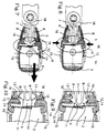
- said blocking body (3) has ( Figures 1 and 2) a cavity (5) in which, by means of a simple operation consisting of a single movement describing a trajectory in a single straight section, penetrates frontally an anchor (6) provided with three planar and parallel blades (7, 8), formed respectively a rigid central blade (7) and two lateral blades (8) which are separated from the central blade (7) by a potential elastic clearance (9) and which, at their point and outwards, each form bulges (10) in opposition, which are defined by an anterior cutaway (11) attached to a flank intermediate (12) which extends back parallel to the side blade (8) itself until reaching a posterior transverse shoulder (13), the cavity having a wall formed of opposite movable edges (14) which belong to respective external pushers (15) which, following said rectilinear trajectory frontal insertion, have a profile which is the opposite of that defined by jointly said front cutaway (11) and said intermediate flank (12), said inverse profiles remaining mutually contiguous during, respectively, the non-pushing state of said pushers
- Figures 4 and 5 clearly show the simple and advantageous according to which, with a single rectilinear and frontal movement, one brings the blocking body against the anchor (6) making it bend elastically its side blades (8) and enters the cavity (5) until, at the bottom thereof, the bulges (10) remain coupled to the movable edges (14) and fixed (16) in a way that can be seen clearly in Figure 8 and which determines the desired attachment of the anchor (6) within the blocking body (3); the initial bending of the side blades (8) ( Figure 4) is facilitated by the effect of inclined plane acting between the front cutaway (11) and the orifice of the cavity (5).
- the stall maneuver is also extremely simple ( Figures 6, 7, 9 and 10) and gives the appreciable advantage of being able to be carried out with one hand.
- said intermediate flank (12) has a convex profile in the direction the width of the elastic blade (8) or the length of said movable edge (14).
- a version of the invention envisages that the anchor (6) is connected to a collar (18) opening rigidly relative to a part of said frame (1) of the vehicle. This is the version which is mainly represented on the drawings attached.
- an anchor (6) as shown in the Figure 3 is used independently of the collar (18) and that it suffices for the latter that the fixing takes place through the hole provided for the axis of articulation, which can be crossed and fixed by any screw.
Landscapes
- Engineering & Computer Science (AREA)
- Mechanical Engineering (AREA)
- Lock And Its Accessories (AREA)
- Clamps And Clips (AREA)
- Motorcycle And Bicycle Frame (AREA)
Abstract
Description
Claims (4)
- Dispositif de fixation perfectionné pour élément antivol de bicyclettes, motocyclettes et analogues, en particulier pour la fixation au cadre (1) du véhicule, pendant les périodes de marche de celui-ci, d'un élément antivol du type de ceux qui sont formés d'une boucle (2) résistante et souple dont une des extrémités est réunie de façon inséparable à un corps de blocage (3) et l'autre extrémité peut être bloquée dans le sein de ce corps de blocage (3) à l'aide d'un mécanisme de fermeture actionnable au moyen d'une clé de serrure (4), caractérisé en ce que ledit corps de blocage (3) possède une cavité (5) dans laquelle, au moyen d'une manoeuvre simple constituée d'un seul mouvement qui décrit une trajectoire ayant un unique tronçon rectiligne, pénètre frontalement un ancrage (6) doté de trois lames (7, 8) planes et parallèles, formées d'une lame centrale (7) rigide et de deux lames latérales (8) qui sont séparées de cette lame centrale (7) par un jeu élastique potentiel (9) et qui, à leur pointe et vers l'extérieur, forment chacune des renflements (10) en opposition qui sont définies par un pan coupé antérieur (11) se rattachant à un flanc intermédiaire (12) qui s'étend en arrière parallèlement à la lame latérale elle-même (8) jusqu'à atteindre un épaulement transversal postérieur (13), ladite cavité possédant une paroi formée de bords mobiles opposés (14) qui appartiennent à des poussoirs externes (15) respectifs et qui, suivant ladite trajectoire rectiligne d'insertion frontale, présentent un profil qui est l'inverse de celui que définissent ensemble ledit pan coupé antérieur (11) et ledit flanc intermédiaire (12), lesdits profils inverses restant mutuellement accolés pendant, respectivement, l'état de non-poussée desdits poussoirs (15) et l'état détendu desdites lames latérales élastiques (8), tandis que, dans ladite cavité (5), existe également une paroi formée de bords fixes opposés (16) qui, dans ledit état détendu des lames élastiques (8), sont situés exactement à l'arrière desdits épaulements postérieurs (13), lesquels épaulements postérieurs (13) dépassent latéralement de leur lame élastique (8) dans une mesure sensiblement moindre que ledit jeu élastique (9) des lames élastiques (8) et que la course possible de rapprochement mutuel desdits bords mobiles (14), ledit ancrage (6) possédant des parties saillantes postérieures (17) qui établissent la limite de pénétration de celui-ci dans ledit corps de blocage (3).
- Dispositif de fixation perfectionné pour élément antivol de bicyclettes, de motocyclettes et analogues, selon la revendication 1, caractérisé en ce que ledit flanc intermédiaire (12) possède un profil convexe dans la direction de la largeur de la lame élastique (8), ou de la longueur dudit bord mobile (14).
- Dispositif de fixation perfectionné pour élément antivol de bicyclettes, de motocyclettes et analogues, selon les revendications précédentes, caractérisé en ce que ledit ancrage (6) est relié à un collier (18) d'ouverture de façon rigide par rapport à une partie dudit cadre (1) du véhicule.
- Dispositif de fixation perfectionné pour élément antivol de bicyclettes, de motocyclettes et analogues, selon les revendications précédentes, caractérisé en ce que ledit ancrage (6) est relié de manière articulée à un dit collier (18).
Applications Claiming Priority (2)
| Application Number | Priority Date | Filing Date | Title |
|---|---|---|---|
| ES9802371 | 1998-11-12 | ||
| ES009802371A ES2165250B1 (es) | 1998-11-12 | 1998-11-12 | Dispositivo de sujecion perfeccionado para un elemento antirrobo de bicicletas, motocicletas y similares. |
Publications (2)
| Publication Number | Publication Date |
|---|---|
| EP1000843A2 true EP1000843A2 (fr) | 2000-05-17 |
| EP1000843A3 EP1000843A3 (fr) | 2002-01-02 |
Family
ID=8305760
Family Applications (1)
| Application Number | Title | Priority Date | Filing Date |
|---|---|---|---|
| EP99402797A Withdrawn EP1000843A3 (fr) | 1998-11-12 | 1999-11-10 | Dispositif de fixation perfectionné pour élément antivol de bicyclette, de motocyclettes et analogues |
Country Status (3)
| Country | Link |
|---|---|
| EP (1) | EP1000843A3 (fr) |
| DE (1) | DE19910075C1 (fr) |
| ES (2) | ES2165250B1 (fr) |
Families Citing this family (4)
| Publication number | Priority date | Publication date | Assignee | Title |
|---|---|---|---|---|
| DE19937125B4 (de) * | 1999-08-06 | 2008-11-13 | Trelock Gmbh | Mitführbefestigung eines Zweiradschlosses an einem Zweirad |
| DE19937126B4 (de) * | 1999-08-06 | 2008-11-13 | Trelock Gmbh | Mitführbefestigung eines Zweiradschlosses an einem Zweirad |
| DE10341783A1 (de) * | 2003-09-10 | 2005-04-28 | Bremicker Soehne Kg A | Halterung zur Befestigung eines Zubehörteils an einem Zweirad |
| TWI246954B (en) | 2004-10-26 | 2006-01-11 | Global Ind Holdings Ltd | Tool box hanging base |
Citations (1)
| Publication number | Priority date | Publication date | Assignee | Title |
|---|---|---|---|---|
| US4736921A (en) | 1985-05-24 | 1988-04-12 | Kbl Corporation | Clamp for holding bicycle lock |
Family Cites Families (11)
| Publication number | Priority date | Publication date | Assignee | Title |
|---|---|---|---|---|
| GB2133830B (en) * | 1983-01-19 | 1986-05-29 | Itw Ltd | Lockable latches |
| US4712280A (en) * | 1985-04-26 | 1987-12-15 | Gerhard Fildan | Strap fastener |
| JPH047772Y2 (fr) * | 1986-11-11 | 1992-02-28 | ||
| US4912950A (en) * | 1988-10-03 | 1990-04-03 | Illinois Tool Works, Inc. | Lockable buckle |
| KR940004657Y1 (ko) * | 1992-01-27 | 1994-07-16 | 시삼암 | 고정편을 결합한 가방 괘정구 |
| DE4312032C3 (de) * | 1992-04-14 | 1999-09-23 | Rixen & Kaul Gmbh | Kupplung zum Befestigen und Lösen von Ausrüstungsgegenständen |
| GB2266337B (en) * | 1992-04-21 | 1995-04-05 | Lincoln Yates | Improvements in or relating to fasteners and fastener devices |
| DE4312033C2 (de) * | 1992-05-12 | 1998-02-12 | Rixen & Kaul Gmbh | Halterung für ein oder mit einem tragbaren Schloß |
| DE9313594U1 (de) * | 1993-09-08 | 1995-01-12 | Winkhaus Fa August | Kabelschloß, insbesondere für Zweiradfahrzeuge |
| JP3494704B2 (ja) * | 1994-08-24 | 2004-02-09 | 株式会社アルファ | 盗難防止装置 |
| DE19532383A1 (de) * | 1995-09-01 | 1997-03-06 | Winkhaus Fa August | Mitführbefestigung eines Zubehörteils an einem mobilen Objekt |
-
1998
- 1998-11-12 ES ES009802371A patent/ES2165250B1/es not_active Expired - Fee Related
-
1999
- 1999-03-08 DE DE19910075A patent/DE19910075C1/de not_active Expired - Lifetime
- 1999-04-16 ES ES009900792A patent/ES2165266B1/es not_active Expired - Fee Related
- 1999-11-10 EP EP99402797A patent/EP1000843A3/fr not_active Withdrawn
Patent Citations (1)
| Publication number | Priority date | Publication date | Assignee | Title |
|---|---|---|---|---|
| US4736921A (en) | 1985-05-24 | 1988-04-12 | Kbl Corporation | Clamp for holding bicycle lock |
Also Published As
| Publication number | Publication date |
|---|---|
| EP1000843A3 (fr) | 2002-01-02 |
| ES2165266B1 (es) | 2003-05-16 |
| ES2165266A1 (es) | 2002-03-01 |
| ES2165250B1 (es) | 2003-05-16 |
| DE19910075C1 (de) | 2000-05-04 |
| ES2165250A1 (es) | 2002-03-01 |
Similar Documents
| Publication | Publication Date | Title |
|---|---|---|
| EP1237453B1 (fr) | Dispositif de prehension pour ustensile de cuisson | |
| FR2614874A1 (fr) | Dispositif de retenue de corde | |
| EP2319349A1 (fr) | Dispositif de fixation d'un bracelet sur une boîte de montre | |
| FR2848597A1 (fr) | Ensemble de rerouillage pour un element mobile de fermeture | |
| CA2524872A1 (fr) | Dispositif antivol a cable pour un cycle et cycle equipe d'un tel dispositif | |
| CA2593966A1 (fr) | Dispositif de verrouillage et de deverrouillage a l'aide d'une cle d'un tampon ou couvercle sur un cadre, notamment de regard de chaussee | |
| FR2510965A3 (fr) | Dispositif pour fixer un element amovible au corps d'un vehicule a moteur a deux roues | |
| FR2601841A1 (fr) | Dispositif electronique de vehicule automobile | |
| EP1000843A2 (fr) | Dispositif de fixation perfectionné pour élément antivol de bicyclette, de motocyclettes et analogues | |
| CH665379A5 (fr) | Necessaire de rasage. | |
| EP1022213B1 (fr) | Pédale automatique de cycle | |
| EP0862097A1 (fr) | Barrette de fixation d'un bracelet de montre et montre munie d'une telle barrette | |
| WO1995025447A1 (fr) | Fermoir pour lien | |
| FR2765852A1 (fr) | Support d'antivol pour bicyclette ou vehicule similaire | |
| FR2652374A1 (fr) | Poignee pour portiere de vehicule a moteur. | |
| FR2669001A1 (fr) | Dispositif de freinage pour bicyclettes ou vehicules similaires. | |
| FR2915227A1 (fr) | Ensemble de poignee exterieure de porte de vehicule automobile. | |
| EP0934870B1 (fr) | Crampon d'assemblage d'un garde-boue pour bicyclette avec une tringle de support | |
| CH703680B1 (fr) | Dispositif de fixation ou d'accouplement rapide. | |
| EP0354840A1 (fr) | Outil de jardin à main comprenant un manche et divers outils montables de façon interchangeable sur ce manche | |
| EP1323881A2 (fr) | Poignée de véhicule automobile, en particulier pour une portière latérale | |
| FR2726110A1 (fr) | Consigneur pour chariot | |
| EP0158152B1 (fr) | Fermoir à double sécurité pour bracelet | |
| FR2980158A1 (fr) | Kit de support de tiers element sur reservoir de motocyclette | |
| FR2585979A1 (fr) | Cutter a changement de lame par l'avant |
Legal Events
| Date | Code | Title | Description |
|---|---|---|---|
| PUAI | Public reference made under article 153(3) epc to a published international application that has entered the european phase |
Free format text: ORIGINAL CODE: 0009012 |
|
| AK | Designated contracting states |
Kind code of ref document: A2 Designated state(s): AT BE CH CY DE DK ES FI FR GB GR IE IT LI LU MC NL PT SE Kind code of ref document: A2 Designated state(s): FR IT NL |
|
| AX | Request for extension of the european patent |
Free format text: AL;LT;LV;MK;RO;SI |
|
| PUAL | Search report despatched |
Free format text: ORIGINAL CODE: 0009013 |
|
| AK | Designated contracting states |
Kind code of ref document: A3 Designated state(s): AT BE CH CY DE DK ES FI FR GB GR IE IT LI LU MC NL PT SE |
|
| AX | Request for extension of the european patent |
Free format text: AL;LT;LV;MK;RO;SI |
|
| 17P | Request for examination filed |
Effective date: 20020625 |
|
| AKX | Designation fees paid |
Free format text: FR IT NL |
|
| REG | Reference to a national code |
Ref country code: DE Ref legal event code: 8566 |
|
| GRAP | Despatch of communication of intention to grant a patent |
Free format text: ORIGINAL CODE: EPIDOSNIGR1 |
|
| STAA | Information on the status of an ep patent application or granted ep patent |
Free format text: STATUS: THE APPLICATION IS DEEMED TO BE WITHDRAWN |
|
| 18D | Application deemed to be withdrawn |
Effective date: 20050524 |