EP0999397B1 - Tubular element with sealing means and a method for manufacturing the tubular element - Google Patents
Tubular element with sealing means and a method for manufacturing the tubular element Download PDFInfo
- Publication number
- EP0999397B1 EP0999397B1 EP98850172A EP98850172A EP0999397B1 EP 0999397 B1 EP0999397 B1 EP 0999397B1 EP 98850172 A EP98850172 A EP 98850172A EP 98850172 A EP98850172 A EP 98850172A EP 0999397 B1 EP0999397 B1 EP 0999397B1
- Authority
- EP
- European Patent Office
- Prior art keywords
- sealing ring
- tubular element
- lip
- sealing
- base
- Prior art date
- Legal status (The legal status is an assumption and is not a legal conclusion. Google has not performed a legal analysis and makes no representation as to the accuracy of the status listed.)
- Expired - Lifetime
Links
Images


Classifications
-
- F—MECHANICAL ENGINEERING; LIGHTING; HEATING; WEAPONS; BLASTING
- F16—ENGINEERING ELEMENTS AND UNITS; GENERAL MEASURES FOR PRODUCING AND MAINTAINING EFFECTIVE FUNCTIONING OF MACHINES OR INSTALLATIONS; THERMAL INSULATION IN GENERAL
- F16L—PIPES; JOINTS OR FITTINGS FOR PIPES; SUPPORTS FOR PIPES, CABLES OR PROTECTIVE TUBING; MEANS FOR THERMAL INSULATION IN GENERAL
- F16L17/00—Joints with packing adapted to sealing by fluid pressure
- F16L17/02—Joints with packing adapted to sealing by fluid pressure with sealing rings arranged between outer surface of pipe and inner surface of sleeve or socket
- F16L17/025—Joints with packing adapted to sealing by fluid pressure with sealing rings arranged between outer surface of pipe and inner surface of sleeve or socket the sealing rings having radially directed ribs
-
- F—MECHANICAL ENGINEERING; LIGHTING; HEATING; WEAPONS; BLASTING
- F16—ENGINEERING ELEMENTS AND UNITS; GENERAL MEASURES FOR PRODUCING AND MAINTAINING EFFECTIVE FUNCTIONING OF MACHINES OR INSTALLATIONS; THERMAL INSULATION IN GENERAL
- F16L—PIPES; JOINTS OR FITTINGS FOR PIPES; SUPPORTS FOR PIPES, CABLES OR PROTECTIVE TUBING; MEANS FOR THERMAL INSULATION IN GENERAL
- F16L21/00—Joints with sleeve or socket
- F16L21/02—Joints with sleeve or socket with elastic sealing rings between pipe and sleeve or between pipe and socket, e.g. with rolling or other prefabricated profiled rings
- F16L21/035—Joints with sleeve or socket with elastic sealing rings between pipe and sleeve or between pipe and socket, e.g. with rolling or other prefabricated profiled rings placed around the spigot end before connection
-
- F—MECHANICAL ENGINEERING; LIGHTING; HEATING; WEAPONS; BLASTING
- F24—HEATING; RANGES; VENTILATING
- F24F—AIR-CONDITIONING; AIR-HUMIDIFICATION; VENTILATION; USE OF AIR CURRENTS FOR SCREENING
- F24F13/00—Details common to, or for air-conditioning, air-humidification, ventilation or use of air currents for screening
- F24F13/02—Ducting arrangements
- F24F13/0209—Ducting arrangements characterised by their connecting means, e.g. flanges
Definitions
- the present invention relates to a tubular element for use in a fluid-conducting duct system, in particular a ventilation duct system, and a method for manufacturing the tubular element (cf. for instance US-A-3,955,834).
- US-A-3,955,834 discloses various modes of providing sealing means in the joint between a tube connector inserted in and interconnecting two tubes.
- Figs 3-9 and 13-15 of this US patent of 1976 show how an external, circumferential, flexible sealing ring having L-shaped cross-section is mounted at the end of a tubular element.
- the sealing ring is placed with its base abutting the outer surface of the tubular element, whereupon the free end portion of the tubular element is bent rearwardly outwards and turned back towards the wall of the tubular element.
- the sealing ring has a sealing lip radially extending away from the base and adapted to seal against an inner surface of an outer tube, in which the tubular element is inserted (see Fig. 8).
- the base of the L-shaped sealing ring is placed on an annular, circumferential step which protrudes radially outwards.
- This step leads to various drawbacks related to the mounting of the sealing ring as well as the structure of the sealing ring and its manufacture.
- the sealing ring When mounting the sealing ring on the tubular body, it is difficult to put the base on the raised step. Normally, this is a manual operation and the person mounting the ring often has to adjust the sealing ring on the raised step before the bending operation. Due to the raised step, the sealing ring has a tendency to slide inwardly on the tubular body during the bending of the end portion of the tubular body. This sliding movement may jeopardise the bending and clamping operation and thereby prevent safe fastening of the sealing ring.
- the bulge on the front end of the sealing ring base is normally not enough to prevent this sliding, especially in cases where the sealing ring material is relatively soft.
- this known L-shaped sealing ring has special drawbacks for tubes of a large diameter, say exceeding about 300 mm.
- the radial dimension of the sealing lip is larger than the axial dimension of the base.
- Such sealing rings have a tendency to "tilt" about 90°, which means that the sealing ring is abutting the wall of the tubular body whereas the sealing ring base is directed radially outwards from the tubular wall. This misplacement has to be corrected manually in mounting.
- the bulge at the free end of the sealing ring base makes it difficult to produce the sealing ring which consists of rubber. Due to the bulge, special tooling has to be used which involve specific drawbacks. The bulge makes it hard to achieve proper release from the mould. Especially when the sealing ring is injection moulded, the bulge is disadvantageous.
- An object of the present invention is to eliminate the disadvantages mentioned above and to provide a tubular element with improved sealing means.
- a further object of the invention is to provide a method of manufacturing such an improved tubular element.
- a specific object of the invention is to provide an improved technique for reliable fastening of the sealing means on the tubular body.
- the sealing ring of the invention Since the sealing ring of the invention is disposed in a groove, it is far more easy to fix the same before the fastening operation compared to the known sealing ring placed on a raised step. Should the sealing ring of the invention for some reason be placed inaccurately before the bending operation, that is partially outside the groove, this is easily remedied. The misplaced sealing ring is only to be somewhat rotated, whereby the sealing ring base automatically finds its way into the groove.
- the sealing ring base is disposed in the groove between defined shoulders of the same, which means that the sealing ring is safely kept in place during the fastening operation.
- the improved sealing ring has no tendency to "tilt" as has been the case with known sealing rings.
- the design of the further lip as well as its connection to the sealing ring base further promote this advantage.
- the base of the new sealing ring has no bulge, which makes the ring easier to manufacture than the known sealing ring discussed above.
- the bent end portion of the tubular element and the bottom of the groove define an annular, circumferential space filled with the further lip and a portion of the sealing ring base.
- said space has a radial width which decreases axially inwards from the end of the tubular element. This feature further enhances the reliable fastening of the sealing ring.
- the sealing ring has a substantially U-shaped cross-section, the flanges of which form the sealing lip and the further lip, respectively. This design of the sealing ring enhances the stiffness of the same, which in turn contributes to secure fastening of the sealing ring in the groove.
- the sealing ring has at least one intermediate sealing lip which is disposed between the sealing lip and the further lip and which is intended to provide an additional sealing against the inner surface of the outer tube, into which the tubular element is inserted.
- Fig. 1 shows a wall portion 1 of a tubular element and a known L-shaped sealing ring having a radial sealing lip 2 and a base 3.
- the wall portion 1 has a raised step 4 on which the base 3 is placed.
- the base 3 has at its free end a bulge 5, around which an end portion 6 of the wall 1 is bent in a manner known per se.
- This sealing means 2, 3 has the drawbacks mentioned above.
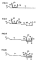
- Figs 2-5 show how a sealing ring generally designated 10 is mounted on a tubular element 11 having a radial, circumferential bead 12.
- the sealing ring 10 of this first embodiment has a base 13 and three lips 14-16 radially extending outwardly away from the base 13.
- the inner lip is a sealing lip 14 adapted to seal against an inner surface of an outer tube, in which the tubular element 11 is inserted (see Fig. 6).
- the outer projection or lip 15 is lower than the sealing lip 14 and takes part in the fastening of the sealing ring 10 as will be described below.
- the intermediate sealing lip 16 provides for additional sealing against the inner surface of the outer tube (Fig. 6).
- a circumferential groove 17 is formed in the wall of the tubular element 11 (Fig. 3).
- a free end portion of the tubular element 11 is bent to form a radially extending flange 18 which defines a shoulder 19 which together with an opposite, spaced shoulder 20, forms the groove 17.
- the sealing ring 10 is axially displaced along the outside of the tubular element 11 (arrow A) from its initial position (Fig. 2) and placed in the groove 17.
- the axial displacement of the sealing ring 10 is promoted by an inclined portion 11a of the wall of the tubular element 11, and the sealing ring base 13 is securely set in the groove 17.
- the wall portion 11a is inclined towards the groove 17.
- the axial width of the groove 17 matches the axial width of the sealing ring base 13.
- the opposite shoulders 19, 20 of the groove 17 axially abut the transitions between the sealing ring base 13 and the sealing lip 14 and the further lip 15, respectively.
- the sealing ring base 13 has no bulge as has the prior-art sealing ring shown in Fig. 1, but has a planar surface in abutment with the planar bottom of the groove 17. In this position (Fig. 4), the further lip 15 extends adjacent to and substantially in parallel with the flange 18.
- the flange 18 is bent further back towards the wall of the tubular element 11 so that the further lip 15 is bent down together with the flange 18 and clamped against the sealing ring base 13 (Fig. 5).
- the radial height of the further lip 15 is calculated in such a way that the free end of the same is approximately radially flush with the free end of the bent flange 18 in the clamped position.
- the further lip 15 must not interfere with the intermediate lip 16 in the clamped position.
- the bent flange 18 preferably extends over approximately half of the axial width of the groove 17 in the clamped position. This structure results in a very secure mounting of the sealing ring 10 at the end of the tubular element 11.
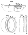
- the section of Fig. 6 shows how the sealing lip 14 seals against the inside of an outer tube 21, in which the tubular element 11 is inserted and the free end of which is stopped by the bead 12.
- the outer tube 21 is a so-called helically wound lock-seam tube having a helical lock seam 22.
- Such tubes are commonly used in ventilation duct systems.
- the intermediate sealing lip 16 seals against the inside of the outer tube 21 and is particularly adapted to seal the helical groove 23, which in certain cases may cause leakage if not sealed. Indeed, the main sealing function is of course provided by the larger sealing lip 14.
- the bent flange 18 and the bottom of the groove 17 define an annular, circumferential space filled with the further lip 15 clamped on a portion of the sealing ring base 13.
- This firm clamping of the further lip 15 guarantees reliable fastening of the sealing ring 10.
- the space between the flange 18 and the bottom of the groove 17 has a radial width which decreases axially inwards from the end of the tubular element 11.
- the space has a frustoconical shape with its smallest radial width approximately in the middle of the groove 17 and its largest radial width adjacent to the end of the tubular element 11.
- Figs 7-8 show the tubular element 11 with the sealing means 10 in accordance with the first embodiment of the invention.
- Fig. 9 shows the sealing ring 10 separately, and the details of the sealing ring 10 can be seen in the cross-section of Fig. 10.
- Fig. 11 shows in a view corresponding to Fig. 9 a sealing ring generally designated 30.
- the sealing ring 30 has two intermediate lips 16a and 16b (Fig. 12) which extend radially away from the sealing ring base 13 and which both are intended to seal against the inside of the outer tube 21 (cf. Fig. 6).
- the two intermediate lips 16a, 16b are parallel and mainly intended to seal the helical groove 23 on the inside of the outer tube 21.
- the sealing lip 14 and the further lip 15 of the sealing ring 30 are of the same design as the corresponding lips of the sealing ring 10 in the first embodiment.
- the axial dimension of the sealing ring base 13 of the modified sealing ring 30 is somewhat greater than that of the sealing ring base 13 in the first embodiment.
- Figs 13-16 which basically correspond to Figs 2-5, still another modified sealing ring 40 is shown, as well as its fastening on the tubular element 11.
- the sealing ring 40 in accordance with this third embodiment is a so-called double-lip sealing ring with no intermediate lip. Since the sealing ring 40 has no intermediate lip, the flange 18 can be bent in such a way that it extends over somewhat more than half of the groove 17 as is shown in Fig. 16. This enhances the clamping effect.
- the tests have also produced good results when the further lip 15 has a thickness greater than that of the sealing lip 14.
- the thickness of the sealing lip 14 and the further lip 15, respectively should decrease radially away from the sealing ring base 13. Since the sealing lip 14 and the further lip 15, respectively, are relatively thick adjacent to the base 13, the stiffness of the sealing ring 10, 30, 40 is promoted. Further, it is preferred that the two lips 14, 15 diverge radially away from the sealing ring base 13, which in particular makes the sealing ring 10, 30, 40 easy to produce.
- the sealing ring 10, 30, 40 is substantially U-shaped in cross-section, the flanges of which form the sealing lip 14 and the further lip 15, respectively, and the web of which forms the base 13.
- the U-shaped design of the sealing ring 10, 30, 40 with its main lips 14 and 15 enhances the stiffness of the sealing ring 30 and thereby promotes secure fixing of the ring 30 in the groove 17.
- the base 13 of the U-shaped sealing ring 10, 30, 40 has no bulge, but is planar which makes the ring easier to manufacture than the known sealing ring shown in Fig. 1.
- the intermediate sealing lip(s) 16, 16a, 16b should preferably have a thickness which is less than that of the sealing lip 14.
- the thickness of the intermediate lips 16, 16a, 16b may also be substantially the same as that of the sealing lip 14, or in certain cases also somewhat thicker (not shown).
- the intermediate lip(s) 16, 16a, 16b should also have a radial height with respect to the sealing ring base 13 that is substantially the same as the radial height of the further lip 15.
- the sealing lip 14 is shown somewhat inclined away from the base 13, but alternatively the lip 14 may also be orthogonal to the base 13 or even somewhat inclined inwards with respect to the base (not shown).
- the further lip 15 may also be orthogonal as an alternative (not shown).
- the sealing ring 10, 30, 40 consists of a flexible polymer material, for instance EPDM rubber.
- the tubular element 11 is for instance of sheet metal, as is the outer tube 21.
- the invention is by no means restricted to the embodiments described above, and modifications are feasible within the scope of the invention defined by the appended claims.
- the number of lips of the sealing ring is not crucial and that the tubular element of the invention may be used in various applications, although ventilation duct systems are the main field of the invention.
- the tubular element may for instance be a connector, a bend, a T-piece or any other fitting used in a ventilation duct system.
Landscapes
- Engineering & Computer Science (AREA)
- General Engineering & Computer Science (AREA)
- Mechanical Engineering (AREA)
- Fluid Mechanics (AREA)
- Combustion & Propulsion (AREA)
- Physics & Mathematics (AREA)
- Chemical & Material Sciences (AREA)
- Gasket Seals (AREA)
- Joints With Sleeves (AREA)
- Lining Or Joining Of Plastics Or The Like (AREA)
- Joints With Pressure Members (AREA)
- Containers And Plastic Fillers For Packaging (AREA)
- Shaping Of Tube Ends By Bending Or Straightening (AREA)
- Duct Arrangements (AREA)
Priority Applications (29)
| Application Number | Priority Date | Filing Date | Title |
|---|---|---|---|
| AT98850172T ATE231596T1 (de) | 1998-11-06 | 1998-11-06 | Rohrförmiges element mit abdichtvorrichtung und verfahren zur herstellung von rohrförmigen elementen |
| DE69810930T DE69810930T2 (de) | 1998-11-06 | 1998-11-06 | Rohrförmiges Element mit Abdichtvorrichtung und Verfahren zur Herstellung von rohrförmigen Elementen |
| AT01101930T ATE273474T1 (de) | 1998-11-06 | 1998-11-06 | Dichtring für röhrenförmiges element |
| EP01101930A EP1106892B1 (en) | 1998-11-06 | 1998-11-06 | Sealing ring for tubular element |
| DK98850172T DK0999397T3 (da) | 1998-11-06 | 1998-11-06 | Rørformet element med forseglingsmidler og fremgangsmåde til fremstilling af det rørformede element |
| DK01101930T DK1106892T3 (da) | 1998-11-06 | 1998-11-06 | Tætningsring til rörformet element |
| DE69825637T DE69825637T2 (de) | 1998-11-06 | 1998-11-06 | Dichtring für röhrenförmiges Element |
| ES01101930T ES2223655T3 (es) | 1998-11-06 | 1998-11-06 | Anillo de estanqueidad para elemento tubular. |
| PT01101930T PT1106892E (pt) | 1998-11-06 | 1998-11-06 | Anel de vedacao para elemento tubular |
| EP98850172A EP0999397B1 (en) | 1998-11-06 | 1998-11-06 | Tubular element with sealing means and a method for manufacturing the tubular element |
| SE9804257A SE514535C2 (sv) | 1998-11-06 | 1998-12-09 | Rörstycke med tätningsorgan samt sätt att framställa ett sådant rörstycke |
| TR2001/03303T TR200103303T2 (tr) | 1998-11-06 | 1999-11-04 | Boru biçiminde parça için conta bileziği. |
| CA002349845A CA2349845A1 (en) | 1998-11-06 | 1999-11-04 | Tubular element with sealing means and a method for manufacturing the tubular element |
| PCT/SE1999/001982 WO2000028253A1 (en) | 1998-11-06 | 1999-11-04 | Tubular element with sealing means and a method for manufacturing the tubular element |
| AU14339/00A AU757428B2 (en) | 1998-11-06 | 1999-11-04 | Tubular element with sealing means and a method for manufacturing the tubular element |
| BR9915053-0A BR9915053A (pt) | 1998-11-06 | 1999-11-04 | Elemento tubular com dispositivo de vedação e processo para fabricar o elemento tubular |
| PL347902A PL192380B1 (pl) | 1998-11-06 | 1999-11-04 | Element rurowy z pierścieniem uszczelniającym dla układu przewodów, zwłaszcza wentylacyjnych, pierścień uszczelniający elementu rurowego i sposób formowania elementu rurowego z pierścieniem uszczelniającym dla układu przewodów, zwłaszcza wentylacyjnych |
| JP2000581397A JP2002529672A (ja) | 1998-11-06 | 1999-11-04 | 密封手段を備えた管状要素及びその製造方法 |
| RU2001114524A RU2239118C2 (ru) | 1998-11-06 | 1999-11-04 | Трубчатый элемент со средствами герметизации и способ изготовления трубчатого элемента |
| HU0104040A HU224605B1 (hu) | 1998-11-06 | 1999-11-04 | Csőszerű elem közegvezető csőrendszerekhez, valamint eljárás ilyen csőszerű elem gyártására |
| HU0303802A HU224603B1 (hu) | 1998-11-06 | 1999-11-04 | Tömítőgyűrű, főleg közegvezető csőrendszerek csőszerű elemeihez |
| CZ20011530A CZ299550B6 (cs) | 1998-11-06 | 1999-11-04 | Trubková soucást, zpusob její výroby a tesnicí kroužek |
| US09/433,234 US6170883B1 (en) | 1998-11-06 | 1999-11-04 | Tubular element with sealing means and a method for manufacturing the tubular element |
| TR2001/01231T TR200101231T2 (tr) | 1998-11-06 | 1999-11-04 | Conta aracı olan boru biçiminde parça ve boru biçiminde parçayı imal etmek için yöntem |
| CNB991234413A CN1166888C (zh) | 1998-11-06 | 1999-11-05 | 管形件、制造管形件的方法和装有管形件的通风管系统 |
| CNB2003101161322A CN1308608C (zh) | 1998-11-06 | 1999-11-05 | 管形件的密封圈 |
| SE0003529A SE515653C2 (sv) | 1998-11-06 | 2000-10-02 | Tätningsring för montering på utsidan av ett rörstycke |
| NO20012192A NO334757B1 (no) | 1998-11-06 | 2001-05-03 | Rørformet element med tetningsorgan og en fremgangsmåte for fremstilling av rørformet element |
| HK01108635.3A HK1037710B (en) | 2001-12-10 | Sealing ring for tubular element |
Applications Claiming Priority (1)
| Application Number | Priority Date | Filing Date | Title |
|---|---|---|---|
| EP98850172A EP0999397B1 (en) | 1998-11-06 | 1998-11-06 | Tubular element with sealing means and a method for manufacturing the tubular element |
Related Child Applications (1)
| Application Number | Title | Priority Date | Filing Date |
|---|---|---|---|
| EP01101930A Division EP1106892B1 (en) | 1998-11-06 | 1998-11-06 | Sealing ring for tubular element |
Publications (2)
| Publication Number | Publication Date |
|---|---|
| EP0999397A1 EP0999397A1 (en) | 2000-05-10 |
| EP0999397B1 true EP0999397B1 (en) | 2003-01-22 |
Family
ID=8236983
Family Applications (2)
| Application Number | Title | Priority Date | Filing Date |
|---|---|---|---|
| EP98850172A Expired - Lifetime EP0999397B1 (en) | 1998-11-06 | 1998-11-06 | Tubular element with sealing means and a method for manufacturing the tubular element |
| EP01101930A Expired - Lifetime EP1106892B1 (en) | 1998-11-06 | 1998-11-06 | Sealing ring for tubular element |
Family Applications After (1)
| Application Number | Title | Priority Date | Filing Date |
|---|---|---|---|
| EP01101930A Expired - Lifetime EP1106892B1 (en) | 1998-11-06 | 1998-11-06 | Sealing ring for tubular element |
Country Status (20)
| Country | Link |
|---|---|
| US (1) | US6170883B1 (es) |
| EP (2) | EP0999397B1 (es) |
| JP (1) | JP2002529672A (es) |
| CN (2) | CN1308608C (es) |
| AT (2) | ATE273474T1 (es) |
| AU (1) | AU757428B2 (es) |
| BR (1) | BR9915053A (es) |
| CA (1) | CA2349845A1 (es) |
| CZ (1) | CZ299550B6 (es) |
| DE (2) | DE69825637T2 (es) |
| DK (2) | DK0999397T3 (es) |
| ES (1) | ES2223655T3 (es) |
| HU (2) | HU224603B1 (es) |
| NO (1) | NO334757B1 (es) |
| PL (1) | PL192380B1 (es) |
| PT (1) | PT1106892E (es) |
| RU (1) | RU2239118C2 (es) |
| SE (2) | SE514535C2 (es) |
| TR (2) | TR200101231T2 (es) |
| WO (1) | WO2000028253A1 (es) |
Cited By (1)
| Publication number | Priority date | Publication date | Assignee | Title |
|---|---|---|---|---|
| RU2652956C2 (ru) * | 2012-11-13 | 2018-05-03 | Линдаб Аб | Уплотнение стыков между вентиляционными воздуховодами и фитингами |
Families Citing this family (53)
| Publication number | Priority date | Publication date | Assignee | Title |
|---|---|---|---|---|
| SE515087C2 (sv) * | 1999-03-24 | 2001-06-11 | Lindab Ab | Rörstycke och förbindning omfattande ett dylikt rörstycke samt ventilationskanalsystem |
| US6367802B1 (en) | 1999-11-30 | 2002-04-09 | Malcolm Mann Inc. | Annular gasket with locking structure |
| US7469905B2 (en) * | 2000-11-30 | 2008-12-30 | Springseal Inc. | Permanently lubricated film gasket and method of manufacture |
| US6550775B2 (en) | 2000-11-30 | 2003-04-22 | Malcolm Mann, Inc. | Annular gasket |
| US20040041347A1 (en) * | 2000-11-30 | 2004-03-04 | Beach Jefferey Kurtis | Permanently lubricated gasket |
| USD521632S1 (en) | 2001-03-20 | 2006-05-23 | Eastern Sheet Metal Llc | Duct with a crimped end |
| USD475778S1 (en) | 2001-03-20 | 2003-06-10 | Eastern Sheet Metal Llc | Offset duct with a crimped end |
| USD501548S1 (en) | 2001-03-20 | 2005-02-01 | Eastern Sheet Metal Llc | Duct tap with an indented end |
| USD475780S1 (en) | 2001-03-20 | 2003-06-10 | Eastern Sheet Metal Llc | Duct with a crimped end |
| USD476074S1 (en) | 2001-03-20 | 2003-06-17 | Eastern Sheet Metal Llc | Duct tap with a crimped end |
| USD523131S1 (en) | 2001-03-20 | 2006-06-13 | Eastern Sheet Metal Llc | Duct with an indented end |
| USD524436S1 (en) | 2001-03-20 | 2006-07-04 | Eastern Sheet Metal Llc | Duct with a crimped end |
| USD478978S1 (en) | 2001-03-20 | 2003-08-26 | Eastern Sheet Metal Llc | Reducer with a crimped end |
| USD527091S1 (en) | 2001-03-20 | 2006-08-22 | Eastern Sheet Metal Llc | Duct with an indented end |
| USD501547S1 (en) | 2001-03-20 | 2005-02-01 | Eastern Sheet Metal Llc | Duct with an indented end |
| USD475130S1 (en) | 2001-03-20 | 2003-05-27 | Eastern Sheet Metal Llc | Bell mouth with a crimped end |
| USD475779S1 (en) | 2001-03-20 | 2003-06-10 | Eastern Sheet Metal Llc | Offset duct with an indented end |
| USD528646S1 (en) | 2001-03-20 | 2006-09-19 | Eastern Sheet Metal Llc | Duct with a crimped end |
| USD475447S1 (en) | 2001-03-20 | 2003-06-03 | Eastern Sheet Metal Llc | Bell mouth with an indented end |
| USD475448S1 (en) | 2001-03-20 | 2003-06-03 | Eastern Sheet Metal Llc | Duct with an indented end |
| USD521633S1 (en) | 2001-03-20 | 2006-05-23 | Eastern Sheet Metal Llc | Duct tap with a crimped end |
| USD480132S1 (en) | 2001-03-20 | 2003-09-30 | Eastern Sheet Metal Llc | Reducer with an indented end |
| USD475449S1 (en) | 2001-03-20 | 2003-06-03 | Eastern Sheet Metal Llc | Duct tap with an indented end |
| US6739632B1 (en) * | 2001-09-24 | 2004-05-25 | Hamlin Sheet Metal, Incorporated | Method and apparatus for coupling HVAC conduits |
| US6866308B2 (en) * | 2003-06-12 | 2005-03-15 | Robert Issagholian-Havai | Interactive sealing system for arcuate ducts including seal compressed and actuated by adjacent expanding seal |
| US7185894B2 (en) * | 2004-06-09 | 2007-03-06 | Advanced Drainage Systems, Inc. | Watertight corrugated pipe gasket |
| US7731884B2 (en) * | 2004-12-08 | 2010-06-08 | Advanced Elastomer Systems, L.P. | Molded gasket and method of making |
| USD521147S1 (en) | 2005-03-24 | 2006-05-16 | Langdon Incorporated | Portion of ductwork |
| USD534253S1 (en) | 2005-03-24 | 2006-12-26 | Langdon Incorporated | Gasket |
| USD529598S1 (en) | 2005-03-24 | 2006-10-03 | Langdon Incorporated | Portion of ductwork |
| US7523964B2 (en) * | 2005-03-24 | 2009-04-28 | Langdon Incorporated | Sealing gasket for ventilation duct system |
| DE112006001582B4 (de) * | 2005-06-14 | 2017-12-07 | Parker-Hannifin Corp. | Dichtungsbaueinheit und Fluidkupplung |
| FR2890717B1 (fr) | 2005-09-15 | 2007-11-23 | Aldes Aeraulique Sa | Joint annulaire d'etancheite pour raccord de conduites de circulation de fluide,telles que des conduites d'air |
| WO2007133094A1 (en) * | 2006-05-12 | 2007-11-22 | Filtercorp International Limited | Cuffed connection system for ducts and tubular members |
| EP2059728A4 (en) * | 2006-09-08 | 2011-01-26 | Lindab Ab | ARRANGEMENT FOR CONNECTING PIPE ELEMENTS IN A VENTILATION CHANNEL SYSTEM |
| FI121974B (fi) * | 2007-05-14 | 2011-06-30 | Flaekt Woods Ab | Menetelmä ilmanvaihtokanavien ja/tai niiden päätelaitteiden välisen tiivisteen muodostamiseksi sekä tiiviste |
| US8474830B2 (en) | 2007-06-07 | 2013-07-02 | Springseal, Inc. | Gasket |
| CA2726090C (en) * | 2008-05-27 | 2017-11-28 | Springseal, Inc. | Pipe coupling assembly |
| DE102010056448B3 (de) * | 2010-12-10 | 2012-01-12 | Oscar McAven | Rohrverbindungsanordnung |
| US20120260488A1 (en) * | 2011-04-18 | 2012-10-18 | Michael Graham | Flange connector and gasket assembly |
| US8801049B2 (en) | 2011-04-29 | 2014-08-12 | Springseal, Inc. | Pipe coupling system and method |
| CA145689S (en) * | 2011-11-16 | 2013-12-17 | Oto Melara Spa | Ring gasket |
| US11338951B1 (en) | 2014-04-07 | 2022-05-24 | Billy Don Hinkle | Bag holder clamp and Method |
| US10563798B1 (en) | 2014-04-07 | 2020-02-18 | Billy Don Hinkle | Compactable pipe T for poly irrigation tubing |
| USD779315S1 (en) * | 2014-04-07 | 2017-02-21 | Billy Don Hinkle | Outer pipe clamp ring |
| EP3015751B2 (en) * | 2014-10-31 | 2024-05-01 | Conex IPR Limited | Fitting for connecting to a tubular element, tubing connection and a method for connecting a fitting to a tubular element |
| FR3047291B1 (fr) | 2016-01-29 | 2018-07-13 | Rikksen | Bague annulaire d'etancheite entre deux conduits, en particulier pour le batiment |
| FR3064336B1 (fr) | 2017-03-21 | 2019-04-19 | Rikksen | Dispositif d'etancheite entre deux conduits coaxiaux et assemblage |
| US11054069B1 (en) | 2017-04-25 | 2021-07-06 | Billy Don Hinkle | Compactable pipe T for poly irrigation tubing |
| CA3128005A1 (en) * | 2019-02-07 | 2020-08-13 | Ips Corporation | Gasketed pipe joint formed in place and method of making same |
| EP4575277A3 (en) * | 2023-12-22 | 2025-08-13 | Vento NV | Sealing rubber for a tubular element |
| BE1032264B1 (nl) * | 2023-12-22 | 2025-07-23 | Vento Nv | Afdichtingsrubber voor een buisvormig element |
| USD1114327S1 (en) * | 2024-04-01 | 2026-02-17 | Heng Yi Technology Company Limited | Levitation base |
Family Cites Families (17)
| Publication number | Priority date | Publication date | Assignee | Title |
|---|---|---|---|---|
| US3015510A (en) | 1956-12-12 | 1962-01-02 | Kenton Schuyler Bates | Pipe sealing gasket |
| DE6930966U (de) | 1968-08-07 | 1970-03-12 | Semperit Gummiwerk Ges M B H D | Muffenrohrdichtung aus elastischem material |
| US3955834A (en) | 1972-02-11 | 1976-05-11 | Aktiebolaget Svenska Flaktfabriken | Apparatus for connecting ducts with a self-sealing joint |
| SE382675B (sv) | 1974-12-12 | 1976-02-09 | Lindab Lindhs Industri Ab | Rorformigt skarvstycke. |
| DE2717487C3 (de) | 1977-04-20 | 1979-10-11 | Wavin B.V., Zwolle (Niederlande) | Extrudiertes Kunststoffrohrteil mit angeformter Muffe |
| DE2733007C2 (de) | 1977-07-21 | 1987-03-19 | Hilti Ag, Schaan | Klebeanker |
| GB1574794A (en) * | 1977-08-05 | 1980-09-10 | Spiro Investment Sa | Connecting lengths of tubing |
| LU78182A1 (fr) * | 1977-09-26 | 1979-05-25 | Spiro Investment Sa | Raccord tubulaire pour la jonction etanche de tubes |
| US4369159A (en) | 1978-04-21 | 1983-01-18 | Wavin B.V. | Plastic socket pipe part and method of manufacturing same |
| NL8201709A (nl) | 1982-04-23 | 1983-11-16 | Wavin Bv | Werkwijze en inrichting voor het vervaardigen van een kunststofbuisdeel met mofeinde. |
| US4664421A (en) | 1986-08-29 | 1987-05-12 | Jones William D | Forgiving profile pipe gasket |
| DE3644834C1 (de) | 1986-12-31 | 1988-04-28 | Vogelsang Ernst Gmbh Co Kg | Rohrverbinder aus Muffe und Einsteckteil |
| FI891341L (fi) * | 1989-03-21 | 1990-09-22 | Rannila Paavo Oy | Roerfoerbindning foer ventilationsanordningar. |
| SE500724C2 (sv) * | 1992-12-28 | 1994-08-15 | Lindab Ab | Tätningsring med U-formigt tvärsnitt samt tätningsanordning med en dylik tätningsring på ett rörstycke |
| SE500398C2 (sv) * | 1992-12-28 | 1994-06-20 | Lindab Ab | Förfarande för fastgöring av en tätningsring på ett rörstycke |
| SE9401319L (sv) | 1994-04-19 | 1995-10-20 | Ellemtel Utvecklings Ab | Telekommunikationssystem |
| IT1285018B1 (it) | 1996-03-19 | 1998-06-03 | Climovent System Sas Di Guazzo | Guarnizione per tubi di ventilazione. |
-
1998
- 1998-11-06 DE DE69825637T patent/DE69825637T2/de not_active Expired - Lifetime
- 1998-11-06 EP EP98850172A patent/EP0999397B1/en not_active Expired - Lifetime
- 1998-11-06 ES ES01101930T patent/ES2223655T3/es not_active Expired - Lifetime
- 1998-11-06 DK DK98850172T patent/DK0999397T3/da active
- 1998-11-06 DK DK01101930T patent/DK1106892T3/da active
- 1998-11-06 AT AT01101930T patent/ATE273474T1/de active
- 1998-11-06 DE DE69810930T patent/DE69810930T2/de not_active Expired - Lifetime
- 1998-11-06 AT AT98850172T patent/ATE231596T1/de not_active IP Right Cessation
- 1998-11-06 PT PT01101930T patent/PT1106892E/pt unknown
- 1998-11-06 EP EP01101930A patent/EP1106892B1/en not_active Expired - Lifetime
- 1998-12-09 SE SE9804257A patent/SE514535C2/sv not_active IP Right Cessation
-
1999
- 1999-11-04 TR TR2001/01231T patent/TR200101231T2/xx unknown
- 1999-11-04 RU RU2001114524A patent/RU2239118C2/ru not_active IP Right Cessation
- 1999-11-04 CZ CZ20011530A patent/CZ299550B6/cs not_active IP Right Cessation
- 1999-11-04 TR TR2001/03303T patent/TR200103303T2/xx unknown
- 1999-11-04 HU HU0303802A patent/HU224603B1/hu not_active IP Right Cessation
- 1999-11-04 BR BR9915053-0A patent/BR9915053A/pt not_active IP Right Cessation
- 1999-11-04 WO PCT/SE1999/001982 patent/WO2000028253A1/en not_active Ceased
- 1999-11-04 JP JP2000581397A patent/JP2002529672A/ja active Pending
- 1999-11-04 US US09/433,234 patent/US6170883B1/en not_active Expired - Fee Related
- 1999-11-04 AU AU14339/00A patent/AU757428B2/en not_active Ceased
- 1999-11-04 PL PL347902A patent/PL192380B1/pl unknown
- 1999-11-04 CA CA002349845A patent/CA2349845A1/en not_active Abandoned
- 1999-11-04 HU HU0104040A patent/HU224605B1/hu not_active IP Right Cessation
- 1999-11-05 CN CNB2003101161322A patent/CN1308608C/zh not_active Expired - Fee Related
- 1999-11-05 CN CNB991234413A patent/CN1166888C/zh not_active Expired - Fee Related
-
2000
- 2000-10-02 SE SE0003529A patent/SE515653C2/sv not_active IP Right Cessation
-
2001
- 2001-05-03 NO NO20012192A patent/NO334757B1/no not_active IP Right Cessation
Cited By (1)
| Publication number | Priority date | Publication date | Assignee | Title |
|---|---|---|---|---|
| RU2652956C2 (ru) * | 2012-11-13 | 2018-05-03 | Линдаб Аб | Уплотнение стыков между вентиляционными воздуховодами и фитингами |
Also Published As
Similar Documents
| Publication | Publication Date | Title |
|---|---|---|
| EP0999397B1 (en) | Tubular element with sealing means and a method for manufacturing the tubular element | |
| US4693483A (en) | Composite gasket and fitting including same | |
| AU634628B2 (en) | Butt connections between two air duct sections made of sheet metal | |
| US4637618A (en) | Composite gasket and fitting including same | |
| US7140618B2 (en) | Socket with dual-functional composite gasket | |
| JPH0579588A (ja) | パイプ継手 | |
| JPS62184827A (ja) | 差し込みスリーブを成形したプラスチック製波形管 | |
| EP1225383A2 (en) | Coupling ring for ventilation ducts, and method of connecting ventilation ducts | |
| US20060214423A1 (en) | Sealing gasket for ventilation duct system | |
| US6712098B2 (en) | Fuel hose, fuel hose connection method, and fuel hose connection structure | |
| JP2753201B2 (ja) | ジョイナおよびストリップ | |
| CA2502267A1 (en) | Improved gasket for duct, pipe and tube joints | |
| US7104574B2 (en) | Corrugated pipe connection joint | |
| JP3998020B2 (ja) | ホースクランプとホースとの接続 | |
| HK1037710B (en) | Sealing ring for tubular element | |
| FI115664B (fi) | Liitosyhde | |
| JP2003524739A (ja) | コルゲートパイプアダプタ及び結合システム | |
| JP4319462B2 (ja) | リブ管用可撓継手 | |
| GB2335008A (en) | Fitting a gaiter without dismantling the joint | |
| EP0940595A1 (en) | Protective gaiters for joints | |
| JP3235816B2 (ja) | 離脱防止管継手 |
Legal Events
| Date | Code | Title | Description |
|---|---|---|---|
| PUAI | Public reference made under article 153(3) epc to a published international application that has entered the european phase |
Free format text: ORIGINAL CODE: 0009012 |
|
| AK | Designated contracting states |
Kind code of ref document: A1 Designated state(s): AT BE CH CY DE DK ES FI FR GB GR IE IT LI LU MC NL PT SE |
|
| AX | Request for extension of the european patent |
Free format text: AL;LT;LV;MK;RO;SI |
|
| 17P | Request for examination filed |
Effective date: 20001103 |
|
| AKX | Designation fees paid |
Free format text: AT BE CH CY DE DK ES FI FR GB GR IE IT LI LU MC NL PT SE |
|
| AXX | Extension fees paid |
Free format text: AL PAYMENT 20001103;LT PAYMENT 20001103;LV PAYMENT 20001103;MK PAYMENT 20001103;RO PAYMENT 20001103;SI PAYMENT 20001103 |
|
| 17Q | First examination report despatched |
Effective date: 20010409 |
|
| GRAG | Despatch of communication of intention to grant |
Free format text: ORIGINAL CODE: EPIDOS AGRA |
|
| GRAG | Despatch of communication of intention to grant |
Free format text: ORIGINAL CODE: EPIDOS AGRA |
|
| GRAH | Despatch of communication of intention to grant a patent |
Free format text: ORIGINAL CODE: EPIDOS IGRA |
|
| GRAH | Despatch of communication of intention to grant a patent |
Free format text: ORIGINAL CODE: EPIDOS IGRA |
|
| GRAA | (expected) grant |
Free format text: ORIGINAL CODE: 0009210 |
|
| AK | Designated contracting states |
Kind code of ref document: B1 Designated state(s): AT BE CH CY DE DK ES FI FR GB GR IE IT LI LU MC NL PT SE |
|
| AX | Request for extension of the european patent |
Free format text: AL PAYMENT 20001103;LT PAYMENT 20001103;LV PAYMENT 20001103;MK PAYMENT 20001103;RO PAYMENT 20001103;SI PAYMENT 20001103 |
|
| PG25 | Lapsed in a contracting state [announced via postgrant information from national office to epo] |
Ref country code: GR Free format text: LAPSE BECAUSE OF FAILURE TO SUBMIT A TRANSLATION OF THE DESCRIPTION OR TO PAY THE FEE WITHIN THE PRESCRIBED TIME-LIMIT Effective date: 20030122 Ref country code: AT Free format text: LAPSE BECAUSE OF FAILURE TO SUBMIT A TRANSLATION OF THE DESCRIPTION OR TO PAY THE FEE WITHIN THE PRESCRIBED TIME-LIMIT Effective date: 20030122 |
|
| REG | Reference to a national code |
Ref country code: GB Ref legal event code: FG4D |
|
| REG | Reference to a national code |
Ref country code: CH Ref legal event code: NV Representative=s name: KIRKER & CIE SA Ref country code: CH Ref legal event code: EP |
|
| REG | Reference to a national code |
Ref country code: IE Ref legal event code: FG4D |
|
| REG | Reference to a national code |
Ref country code: DK Ref legal event code: T3 |
|
| REF | Corresponds to: |
Ref document number: 69810930 Country of ref document: DE Date of ref document: 20030227 Kind code of ref document: P |
|
| PG25 | Lapsed in a contracting state [announced via postgrant information from national office to epo] |
Ref country code: SE Free format text: LAPSE BECAUSE OF FAILURE TO SUBMIT A TRANSLATION OF THE DESCRIPTION OR TO PAY THE FEE WITHIN THE PRESCRIBED TIME-LIMIT Effective date: 20030422 Ref country code: PT Free format text: LAPSE BECAUSE OF FAILURE TO SUBMIT A TRANSLATION OF THE DESCRIPTION OR TO PAY THE FEE WITHIN THE PRESCRIBED TIME-LIMIT Effective date: 20030422 |
|
| LTIE | Lt: invalidation of european patent or patent extension |
Effective date: 20030122 |
|
| PG25 | Lapsed in a contracting state [announced via postgrant information from national office to epo] |
Ref country code: ES Free format text: LAPSE BECAUSE OF FAILURE TO SUBMIT A TRANSLATION OF THE DESCRIPTION OR TO PAY THE FEE WITHIN THE PRESCRIBED TIME-LIMIT Effective date: 20030730 |
|
| ET | Fr: translation filed | ||
| PG25 | Lapsed in a contracting state [announced via postgrant information from national office to epo] |
Ref country code: LU Free format text: LAPSE BECAUSE OF NON-PAYMENT OF DUE FEES Effective date: 20031106 Ref country code: IE Free format text: LAPSE BECAUSE OF NON-PAYMENT OF DUE FEES Effective date: 20031106 Ref country code: CY Free format text: LAPSE BECAUSE OF FAILURE TO SUBMIT A TRANSLATION OF THE DESCRIPTION OR TO PAY THE FEE WITHIN THE PRESCRIBED TIME-LIMIT Effective date: 20031106 |
|
| PLBE | No opposition filed within time limit |
Free format text: ORIGINAL CODE: 0009261 |
|
| STAA | Information on the status of an ep patent application or granted ep patent |
Free format text: STATUS: NO OPPOSITION FILED WITHIN TIME LIMIT |
|
| PG25 | Lapsed in a contracting state [announced via postgrant information from national office to epo] |
Ref country code: MC Free format text: LAPSE BECAUSE OF NON-PAYMENT OF DUE FEES Effective date: 20031130 |
|
| 26N | No opposition filed |
Effective date: 20031023 |
|
| REG | Reference to a national code |
Ref country code: IE Ref legal event code: MM4A |
|
| PGFP | Annual fee paid to national office [announced via postgrant information from national office to epo] |
Ref country code: DK Payment date: 20061114 Year of fee payment: 9 |
|
| REG | Reference to a national code |
Ref country code: DK Ref legal event code: EBP |
|
| PG25 | Lapsed in a contracting state [announced via postgrant information from national office to epo] |
Ref country code: DK Free format text: LAPSE BECAUSE OF NON-PAYMENT OF DUE FEES Effective date: 20071130 |
|
| REG | Reference to a national code |
Ref country code: FR Ref legal event code: PLFP Year of fee payment: 18 |
|
| REG | Reference to a national code |
Ref country code: FR Ref legal event code: PLFP Year of fee payment: 19 |
|
| REG | Reference to a national code |
Ref country code: FR Ref legal event code: PLFP Year of fee payment: 20 |
|
| PGFP | Annual fee paid to national office [announced via postgrant information from national office to epo] |
Ref country code: NL Payment date: 20171115 Year of fee payment: 20 Ref country code: FI Payment date: 20171109 Year of fee payment: 20 Ref country code: FR Payment date: 20171026 Year of fee payment: 20 Ref country code: DE Payment date: 20171031 Year of fee payment: 20 |
|
| PGFP | Annual fee paid to national office [announced via postgrant information from national office to epo] |
Ref country code: GB Payment date: 20171101 Year of fee payment: 20 Ref country code: BE Payment date: 20171013 Year of fee payment: 20 Ref country code: IT Payment date: 20171123 Year of fee payment: 20 Ref country code: CH Payment date: 20171114 Year of fee payment: 20 |
|
| REG | Reference to a national code |
Ref country code: DE Ref legal event code: R071 Ref document number: 69810930 Country of ref document: DE |
|
| REG | Reference to a national code |
Ref country code: NL Ref legal event code: MK Effective date: 20181105 |
|
| REG | Reference to a national code |
Ref country code: CH Ref legal event code: PL |
|
| REG | Reference to a national code |
Ref country code: GB Ref legal event code: PE20 Expiry date: 20181105 |
|
| REG | Reference to a national code |
Ref country code: BE Ref legal event code: MK Effective date: 20181106 |
|
| PG25 | Lapsed in a contracting state [announced via postgrant information from national office to epo] |
Ref country code: GB Free format text: LAPSE BECAUSE OF EXPIRATION OF PROTECTION Effective date: 20181105 |