EP0998393B1 - Ink bottle with puncturable diaphragm closure - Google Patents
Ink bottle with puncturable diaphragm closure Download PDFInfo
- Publication number
- EP0998393B1 EP0998393B1 EP98935205A EP98935205A EP0998393B1 EP 0998393 B1 EP0998393 B1 EP 0998393B1 EP 98935205 A EP98935205 A EP 98935205A EP 98935205 A EP98935205 A EP 98935205A EP 0998393 B1 EP0998393 B1 EP 0998393B1
- Authority
- EP
- European Patent Office
- Prior art keywords
- ink
- diaphragm
- reservoir
- bottle
- puncturing member
- Prior art date
- Legal status (The legal status is an assumption and is not a legal conclusion. Google has not performed a legal analysis and makes no representation as to the accuracy of the status listed.)
- Expired - Lifetime
Links
Images
Classifications
-
- B—PERFORMING OPERATIONS; TRANSPORTING
- B41—PRINTING; LINING MACHINES; TYPEWRITERS; STAMPS
- B41J—TYPEWRITERS; SELECTIVE PRINTING MECHANISMS, i.e. MECHANISMS PRINTING OTHERWISE THAN FROM A FORME; CORRECTION OF TYPOGRAPHICAL ERRORS
- B41J2/00—Typewriters or selective printing mechanisms characterised by the printing or marking process for which they are designed
- B41J2/005—Typewriters or selective printing mechanisms characterised by the printing or marking process for which they are designed characterised by bringing liquid or particles selectively into contact with a printing material
- B41J2/01—Ink jet
- B41J2/17—Ink jet characterised by ink handling
- B41J2/175—Ink supply systems ; Circuit parts therefor
- B41J2/17503—Ink cartridges
- B41J2/1752—Mounting within the printer
- B41J2/17523—Ink connection
-
- B—PERFORMING OPERATIONS; TRANSPORTING
- B41—PRINTING; LINING MACHINES; TYPEWRITERS; STAMPS
- B41J—TYPEWRITERS; SELECTIVE PRINTING MECHANISMS, i.e. MECHANISMS PRINTING OTHERWISE THAN FROM A FORME; CORRECTION OF TYPOGRAPHICAL ERRORS
- B41J2/00—Typewriters or selective printing mechanisms characterised by the printing or marking process for which they are designed
- B41J2/005—Typewriters or selective printing mechanisms characterised by the printing or marking process for which they are designed characterised by bringing liquid or particles selectively into contact with a printing material
- B41J2/01—Ink jet
- B41J2/17—Ink jet characterised by ink handling
- B41J2/1721—Collecting waste ink; Collectors therefor
- B41J2/1728—Closed waste ink collectors
- B41J2/1735—Closed waste ink collectors with ink supply tank in common containers
-
- B—PERFORMING OPERATIONS; TRANSPORTING
- B41—PRINTING; LINING MACHINES; TYPEWRITERS; STAMPS
- B41J—TYPEWRITERS; SELECTIVE PRINTING MECHANISMS, i.e. MECHANISMS PRINTING OTHERWISE THAN FROM A FORME; CORRECTION OF TYPOGRAPHICAL ERRORS
- B41J2/00—Typewriters or selective printing mechanisms characterised by the printing or marking process for which they are designed
- B41J2/005—Typewriters or selective printing mechanisms characterised by the printing or marking process for which they are designed characterised by bringing liquid or particles selectively into contact with a printing material
- B41J2/01—Ink jet
- B41J2/17—Ink jet characterised by ink handling
- B41J2/175—Ink supply systems ; Circuit parts therefor
- B41J2/17503—Ink cartridges
- B41J2/17506—Refilling of the cartridge
- B41J2/17509—Whilst mounted in the printer
-
- B—PERFORMING OPERATIONS; TRANSPORTING
- B41—PRINTING; LINING MACHINES; TYPEWRITERS; STAMPS
- B41J—TYPEWRITERS; SELECTIVE PRINTING MECHANISMS, i.e. MECHANISMS PRINTING OTHERWISE THAN FROM A FORME; CORRECTION OF TYPOGRAPHICAL ERRORS
- B41J2/00—Typewriters or selective printing mechanisms characterised by the printing or marking process for which they are designed
- B41J2/005—Typewriters or selective printing mechanisms characterised by the printing or marking process for which they are designed characterised by bringing liquid or particles selectively into contact with a printing material
- B41J2/01—Ink jet
- B41J2/17—Ink jet characterised by ink handling
- B41J2/175—Ink supply systems ; Circuit parts therefor
- B41J2/17503—Ink cartridges
- B41J2/17513—Inner structure
-
- B—PERFORMING OPERATIONS; TRANSPORTING
- B41—PRINTING; LINING MACHINES; TYPEWRITERS; STAMPS
- B41J—TYPEWRITERS; SELECTIVE PRINTING MECHANISMS, i.e. MECHANISMS PRINTING OTHERWISE THAN FROM A FORME; CORRECTION OF TYPOGRAPHICAL ERRORS
- B41J2/00—Typewriters or selective printing mechanisms characterised by the printing or marking process for which they are designed
- B41J2/005—Typewriters or selective printing mechanisms characterised by the printing or marking process for which they are designed characterised by bringing liquid or particles selectively into contact with a printing material
- B41J2/01—Ink jet
- B41J2/17—Ink jet characterised by ink handling
- B41J2/175—Ink supply systems ; Circuit parts therefor
- B41J2/17566—Ink level or ink residue control
Definitions
- This invention relates to an ink bottle (or other container) for containing a supply of ink for an ink jet printing system.
- the ink jet printing apparatus for which the ink bottle of the present invention is intended for use is generally referred to as an industrial type ink jet printing system (as opposed to an office ink jet printer) which typically is used to print indicia on packaging or on secondary packaging of products conveyed past the ink jet printhead of this system as the products in their packages are conveyed past the printhead on a conveyor belt or the like.
- industrial ink jet printing systems typically use considerably more ink in a given time than office ink jet printers because the area printed by such industrial printers is greater and the industrial printing systems operate continuously.
- ink was supplied to such commercial ink jet printing systems by means of a disposable ink bottle holding a desired quantity of ink, e.g. a pint (0.4732 litres) or a litre.
- a desired quantity of ink e.g. a pint (0.4732 litres) or a litre.
- U. S. Patent 5,343,226 entitled “Ink Jet Ink Supply Apparatus” which has a spring biased poppet valve incorporated in a screw on cap such that when the bottle is inverted and threaded into a receptacle in the ink jet printing apparatus, a finger will engage the normally closed spring biased valve in the cap, and will force the valve to open, thus allowing ink from within the bottle to fill a reservoir of the ink jet printing apparatus.
- the valve Upon removal of the ink bottle from the ink jet printing apparatus, the valve will close under the bias of the spring, and thus the valve will prevent the flow of ink from the bottle as it is removed. While such bottles worked well for their intended purpose, the necessity of including the spring biased valve in the cap of each bottle is expensive.
- EP-A-0322131 represents the closest prior art and discloses a process and system for supplying ink to an ink jet pen wherein an off board ink supply is provided remote from the pen, and ink is fed from this supply to the pen by capillary action created during an ink jet printing operation.
- the pen includes a porous storage medium which is initially filled with ink at a slightly negative head. However, this negative head increases during ink depletion from the storage medium and provides the capillary forces necessary to pull ink into the storage medium from the off board ink supply.
- the driving energy for this action is provided by current drive to a thin film printhead of the pen, thus rendering the printhead multi-functional in purpose and simplifying the ink supply apparatus therefor.
- the use of an intermediate porous storage medium enables the ink supply system to accommodate large rates of changes in ink demand from the pen while still affording the user with a large ink capacity system in which disposable pens may be readily and easily replaced in a userfriendly operation.
- an ink jet printing apparatus comprising: an ink reservoir; a replaceable ink container for supplying ink to said reservoir, said container having a supply of ink therein; a puncturable diaphragm closing said container; a single hollow puncturing member carried by said ink reservoir, ink in said container being exchangeable for air via the passage through said puncturing member, said puncturing member being engageable with said diaphragm upon said diaphragm facing said puncturing member, upon said container and said diaphragm being moved toward said puncturing member said puncturing member piercing an opening through said diaphragm and said diaphragm sealingly engaging the sides of said puncturing member so as to substantially prevent ink from leaking between said puncturing member and said diaphragm, said puncturing member opening communication between the ink within said container and said ink reservoir thereby permitting ink to flow through said passage in the puncturing member from said container into said ink reservoir, said diaphragm opening substantially closing upon
- an ink bottle for an ink jet printing system having an ink reservoir for holding a supply of ink for said ink jet printing system, said bottle having a closed container body having a mouth at one end thereof, a puncturable diaphragm sealingly secured to said mouth closing the bottle, said diaphragm being a sheet of resilient elastomeric material, a cap secured to said mouth and overlying said diaphragm, said cap having an opening therethrough exposing a portion of said diaphragm so as to be pierced by a puncturing member carried by said ink reservoir when the bottle is installed in said ink jet printing system in inverted position with the mouth facing downwardly such that ink from within said bottle and atmospheric air are exchanged via a passage through said puncturing member, said diaphragm sealingly engaging the sides of said puncturing member so as to substantially prevent ink from leaking between said puncturing member and said diaphragm, said diaphragm re-
- an ink supply system for an ink jet printing apparatus comprising an ink reservoir for containing a supply of ink which is supplied to an ink jet printing head or the like, a replaceable ink bottle for containing a supply of ink for said ink reservoir, an ink bottle diaphragm carried by said ink bottle, a single hollow puncturing member carried by said ink reservoir, ink in said bottle being exchangeable for air via the passage through said puncturing member, said puncturing member being engageable with said diaphragm upon said ink bottle being moved toward said puncturing member so that said puncturing member punctures through said diaphragm, said puncturing member being sealingly engageable with said diaphragm so as to substantially prevent the leakage of ink between said puncturing member and the region of said diaphragm in engagement with said puncturing member, and an air path between the outside atmosphere and said reservoir enabling the exchange of air and ink within said ink bottle via said passage through said puncturing member, said diaphra
- a method of supplying ink to an ink jet printing system having a closed ink reservoir, a single puncturing tube extending above the reservoir and providing via the passage therethrough communication to the interior of said reservoir with said puncturing tube extending downwardly within said reservoir to a predetermined level, an air passageway extending from the atmosphere exteriorly of said reservoir to said reservoir, and an ink bottle having a puncturable diaphragm
- said method comprising the steps of: orienting said ink bottle such that said diaphragm faces said puncturing tube; causing said puncturing tube to pierce through said diaphragm thereby to open communication via the passage through the tube between the interior of said ink bottle and said reservoir such that ink from within said ink bottle may flow into said reservoir, said diaphragm sealingly engaging the sides of said puncturing tube so as to substantially prevent ink from leaking between said puncturing tube and said diaphragm; allowing the exchange of ink from said bottle into said reservoir and
- the embodiment of the invention is intended for use with an ink jet printing apparatus having an ink reservoir for receiving a supply of ink from a replaceable ink container, the latter having a mouth and a supply of ink within the container, the ink reservoir having an ink well for containing a supply of ink.
- the embodiment includes a resilient, puncturable diaphragm closing the mouth of the container.
- a puncturing member is carried by the ink reservoir of the ink jet printing apparatus. The puncturing member is engageable with the diaphragm upon the container being inverted such that the diaphragm faces downwardly as the container and the diaphragm are moved downwardly on the puncturing member so that the puncturing member pierces through the diaphragm.
- the puncturing member puncturing through the diaphragm, the latter sealingly engages the sides of the puncturing tube so as to substantially prevent the ink from leaking therepast.
- the puncturing member opens communication between the ink within the container and the ink reservoir thereby permitting ink to flow from the bottle into the ink reservoir via the puncturing member.
- An air path is provided which is in communication with the atmosphere and with the reservoir so that ink from within the container and atmospheric air may be exchanged via the puncturing member so that ink is free to flow from the container into the reservoir and so that the pressure within the container is maintained substantially at atmospheric pressure.
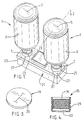
- an ink supply system for an ink jet printing apparatus is shown in which an ink bottle or container 1 supplies ink to the printhead of the ink jet printing apparatus.
- an ink bottle or container 1 supplies ink to the printhead of the ink jet printing apparatus.
- the ink bottle 1 and such structure from the ink jet printing apparatus as is needed to interface with and to receive the ink from the bottle 1 are herein described.
- bottle 1 is in an inverted position when it is installed in the ink jet printing apparatus.
- Bottle 1 has a bottle body 3 having a closed bottom 5, a neck 7, and a mouth 9.
- the neck 7 of the bottle 1 has suitable external screw threads 11 (see Fig. 5) formed on the outer surface thereof and a suitable over cap 15 having internal threads 16 (see Fig. 5) is threaded onto threads 11 on neck 7 of bottle 1.
- bottle 1 contains a supply of ink 17.
- bottle 1 is a semi-rigid bottle blow molded of a suitable synthetic resin, such as a suitable high density polyethylene (HDPE) or the like, which is compatible with ink 17 contained within the bottle.
- HDPE high density polyethylene
- a resilient, elastomeric diaphragm or membrane 19 covering the open mouth of the bottle 1 is sealably secured to the mouth 9 of the bottle so as to seal the ink within the bottle.
- diaphragm 19 is of a suitable elastomeric sheet material, such as natural rubber or sheet silicone material.
- LDPE low density polyethylene
- the elastomeric material from which diaphragm 19 is formed preferably has sufficient memory that after being deformed, the diaphragm will quickly and resiliently return to its flat position, as shown in Fig. 2.
- diaphragm 19 is interposed between the underside of cap 15 and the edge of bottle mouth 9 such that when the cap is tightly screwed in place on the neck of the bottle, the diaphragm will be tightly gripped between the bottle mouth and the cap, thereby sealing it therebetween.
- the diaphragm also may be sealing secured by the mouth of the bottle as by ultrasonically welding or the like.
- elastomeric diaphragm 19 may have an optional, pre-formed slit 20 therein.
- Slit 20 is preferably not fully through the thickness of the diaphragm, but instead is a line (area) of weakness which will open or tear upon installation of bottle 1 in the ink jet printing apparatus as will be more fully described hereinafter.
- slit 20 is not required, as the piercing member, as will be hereinafter described, may puncture the diaphragm without the pre-formed area of weakness.
- slit 20 is shown to be a single slit, multiple star shaped or pie slice shaped slits (or other area of weakness) also may be used.
- an ink reservoir of the ink jet printing apparatus has an ink well 22a which holds a supply 22 of ink dispensed from bottle 1 for use by the ink jet printing apparatus.
- Ink from reservoir 21 is conveyed to the printhead (not shown) of the ink jet printing apparatus so as to print desired indicia on objects in the manner well known to those skilled in the art.
- the ink supply tube from reservoir 21 to the printhead is not shown.
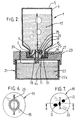
- Reservoir 21 has a reservoir lid 23 enclosing the ink within the reservoir.
- Reservoir lid 23 has two recesses or sockets 25 formed in the upper portion thereof for receiving the cap 15 of a respective bottle 1.
- each recess 25 has female threads 27 (see Figs. 2 and 5) on its vertical sides and cap 15 has mating male threads 29 on its outer sides engageable with female threads 27.
- a gasket 31 having a center opening 32 is interposed between the cap 15 and the base of recess 25 so that upon screwing cap 15 into recess 25, the cap will sealingly engage gasket 31 and seal the cap to the reservoir lid 23.
- cap 15 in addition to being screwed onto the bottle neck 7, is adhesively bonded (or otherwise secured) to the bottle such that the cap will not unscrew. As shown in Figs.
- cap 15 has a center opening 33 which exposes a portion of diaphragm 19 through gasket 31.
- Reservoir lid 23 has a puncturing or piercing member or septum 35 fixed with respect to the reservoir lid 23 and extending upwardly within center of recess 25.
- puncturing member 35 is a hollow, tubular member which, as will be herein described in detail, allows air and ink exchange therethrough.
- the diameter of piercing tube 35 is sized relative to the density and viscosity of the ink and relative to the resilient and elastomeric properties of the diaphragm 19 such that the piercing tube will readily pierce the diaphragm and leak past the diaphragm will be minimized. As shown in Fig.
- piercing tube 35 is supported by an open spider structure 39 having one or more passages 41 extending from the area below gasket 33 downwardly into reservoir 21. In this manner, any ink that seeps or leaks between slit 20 of diaphragm 19 and piercing tube 35 drains into the reservoir and is not wasted.
- a typical ink used for ink jet printing may have a surface tension of about 35 dyne/cm. and a viscosity as high as about 350 centipoise.
- Diaphragm 19 may be of sheet silicone elastomer commercially available from SFS Industries of Santa Fe Springs, California having a thickness of 2.38mm (3/32 inches) and a Shore hardness of about 70A.
- the diameter of the mouth 9 of bottle 1 is about 37.59mm (1.48 inches) and the length of pre-formed slit 20 in diaphragm 19 is about 20.32mm (0.8 inches).
- Piercing tube 35 is a length of stainless steel tubing having an outer diameter of about 9.525mm (0.375 inches).
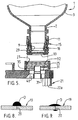
- diaphragm 19 have a surface energy less than the surface tension of ink 17 such that droplets D of ink (as shown in Fig. 8) will bead up on the surface of diaphragm 19 and will bridge a re-closed slit 20 such that ink will not wick through the slit by capillary action.
- the resilient nature of the diaphragm upon removal of a partially filled bottle 3 from piercing tube 35, the resilient nature of the diaphragm will cause slit 20 to re-close and the lower surface energy of the diaphragm material will prevent loss of ink.
- the elastomeric material of diaphragm 19 should have a lower surface energy of about 20 dyne/cm. to yield the ink beading as shown in Fig. 8.
- the surface energy is greater than the surface tension of the ink, the ink droplet D', as shown in Fig. 9, will not bridge re-closed slit 20 and will wick through or leak through the slit.
- the filled ink bottle 1 is inverted such that its cap 15 faces downwardly.
- the cap 15 is inserted into socket 25 and the male threads 29 on the outer surface of the cap 15 are threaded into female threads 27 in socket 25.
- the upper end of piercing member 35 engages the pre-formed area of weakness (slit 20) and punctures through the membrane 19 along the pre-formed slit (or line of weakness) 20.
- the membrane 19 resiliently grips the outer surface of the piercing member 35 and seals the outer surface of the piercing member 35 relative to the membrane 19 thereby to substantially prevent ink from leaking from the interface of the piercing member 35 and the membrane 19.
- ink will flow from the bottle 1 into the reservoir 21.
- reservoir lid 23 has an air path 37 therethrough which allows atmospheric air to enter reservoir 21 and to permit the exchange of air and ink within bottle 1 via piercing tube 35 as ink flows from the bottle, into ink reservoir 21.
- the level of the ink 22 in reservoir 21 is at the level of the lower end of the piercing tube 35.
- the bottle is merely unscrewed from the female threads 27 in reservoir lid 23.
- diaphragm 19 will maintain sealing engagement with the outer surface of piercing tube 35.
- the resilient membrane 19 will spring closed so as to effectively close slit 20 (or other opening punctured through the membrane), thus retaining ink remaining in the bottle 1.
- the resilient characteristics of the membrane 19 cause the slit 20 to act as a normally closed valve which upon removal of the piercing tube automatically and quickly closes.
- a partly filled bottle may be removed from the piercing tube 35 substantially without spillage or leakage of ink, even though the bottle is in an inverted dispensing position.
- the slit 20 in membrane 19 resiliently closes, any remaining ink within the bottle is maintained in a closed container, thus preventing evaporation of solvents and preventing air borne contaminants from entering the ink bottle. Because of the open spider support structure 39 for piercing tube 35 and openings 41, in the event ink leaks from slit 20 as the bottle is removed, the ink will flow into reservoir and is not wasted.
Landscapes
- Ink Jet (AREA)
- Closures For Containers (AREA)
- Containers And Packaging Bodies Having A Special Means To Remove Contents (AREA)
- Devices For Use In Laboratory Experiments (AREA)
Applications Claiming Priority (3)
| Application Number | Priority Date | Filing Date | Title |
|---|---|---|---|
| US08/898,802 US6079823A (en) | 1997-07-23 | 1997-07-23 | Ink bottle with puncturable diaphragm closure |
| PCT/GB1998/002206 WO1999004979A1 (en) | 1997-07-23 | 1998-07-23 | Ink bottle with puncturable diaphragm closure |
| US898802 | 2001-07-03 |
Publications (2)
| Publication Number | Publication Date |
|---|---|
| EP0998393A1 EP0998393A1 (en) | 2000-05-10 |
| EP0998393B1 true EP0998393B1 (en) | 2002-12-04 |
Family
ID=25410055
Family Applications (1)
| Application Number | Title | Priority Date | Filing Date |
|---|---|---|---|
| EP98935205A Expired - Lifetime EP0998393B1 (en) | 1997-07-23 | 1998-07-23 | Ink bottle with puncturable diaphragm closure |
Country Status (12)
| Country | Link |
|---|---|
| US (1) | US6079823A (enExample) |
| EP (1) | EP0998393B1 (enExample) |
| JP (1) | JP2001510752A (enExample) |
| KR (1) | KR20010022157A (enExample) |
| CN (1) | CN1103691C (enExample) |
| AT (1) | ATE228936T1 (enExample) |
| AU (1) | AU746516C (enExample) |
| BR (1) | BR9815560A (enExample) |
| CA (1) | CA2297238A1 (enExample) |
| DE (1) | DE69809918T2 (enExample) |
| RU (1) | RU2000104278A (enExample) |
| WO (1) | WO1999004979A1 (enExample) |
Cited By (3)
| Publication number | Priority date | Publication date | Assignee | Title |
|---|---|---|---|---|
| US11174058B2 (en) | 2018-05-15 | 2021-11-16 | Hewlett-Packard Development Company, L.P. | Seal removal structure |
| US12103312B2 (en) | 2021-09-17 | 2024-10-01 | Seiko Epson Corporation | Ink replenishment container |
| US12172447B2 (en) | 2021-09-30 | 2024-12-24 | Seiko Epson Corporation | Ink replenishment container |
Families Citing this family (63)
| Publication number | Priority date | Publication date | Assignee | Title |
|---|---|---|---|---|
| US6164768A (en) * | 1999-11-09 | 2000-12-26 | Illinois Tool Works Inc. | Adapter and mating bottle cap for coupling bottles to ink supplies |
| JP2001191547A (ja) * | 2000-01-11 | 2001-07-17 | Seiko Epson Corp | インクジェット記録装置用インクカートリッジおよびインクジェット記録装置 |
| WO2002036347A2 (en) | 2000-10-31 | 2002-05-10 | Zipher Limited | Printing apparatus |
| FR2816241B1 (fr) * | 2000-11-07 | 2003-03-28 | Segepar | Systeme anti-retour pour circuit d'alimentation en encre et cartouche d'encre |
| JP2002307713A (ja) * | 2001-02-09 | 2002-10-23 | Canon Inc | 液体噴射装置 |
| JP3796439B2 (ja) * | 2001-02-09 | 2006-07-12 | キヤノン株式会社 | 液体収納容器 |
| JP2003127412A (ja) * | 2001-10-19 | 2003-05-08 | Sony Corp | インク供給装置及びプリンタヘッド |
| US6962408B2 (en) * | 2002-01-30 | 2005-11-08 | Hewlett-Packard Development Company, L.P. | Printing-fluid container |
| US6805336B2 (en) * | 2002-03-04 | 2004-10-19 | Emerson Electric Co. | Self-sealing dispensing valve for humidifier water bottles |
| KR100411332B1 (en) * | 2003-02-12 | 2003-12-24 | Taeil Systems Co Ltd | Automatic ink feeding device |
| JP4161846B2 (ja) * | 2003-08-08 | 2008-10-08 | セイコーエプソン株式会社 | 液体収容体 |
| US7300138B2 (en) | 2004-01-08 | 2007-11-27 | Eastman Kodak Company | Replaceable ink container for inkjet printer |
| US7543920B2 (en) * | 2004-01-09 | 2009-06-09 | Videojet Technologies Inc. | System and method for connecting an ink bottle to an ink reservoir of an ink jet printing system |
| CN101027187B (zh) * | 2004-01-09 | 2011-07-06 | 录象射流技术公司 | 将墨盒连接到喷墨打印系统的储墨仓的系统和方法 |
| EP1920937A3 (en) | 2004-01-09 | 2009-03-11 | Videojet Technologies Inc. | System and method for connecting an ink bottle to an ink reservoir of an ink jet printing system |
| GB2412088B (en) | 2004-03-19 | 2007-09-19 | Zipher Ltd | Liquid supply system |
| US20060290015A1 (en) * | 2005-06-23 | 2006-12-28 | Emerson Electric Co. | Humidifier and fluid dispensing valve therefor |
| US20070222832A1 (en) * | 2006-03-22 | 2007-09-27 | Fujifilm Corporation | Ink tank assembly for inkjet system, and image forming apparatus |
| GB0720406D0 (en) * | 2007-10-19 | 2007-12-05 | Airbus Uk Ltd | Tank for containing a fluid within a chamber |
| US8292417B2 (en) * | 2007-11-30 | 2012-10-23 | Brother Kogyo Kabushiki Kaisha | Ink cartridges and methods of manufacturing such ink cartridges |
| JP5151424B2 (ja) * | 2007-11-30 | 2013-02-27 | ブラザー工業株式会社 | インクカートリッジ |
| US8322836B2 (en) * | 2009-04-15 | 2012-12-04 | Electronics For Imaging, Inc. | Liquid ink container and ink delivery station |
| CN105667095B (zh) * | 2010-05-17 | 2017-09-01 | 麦捷特技术有限公司 | 用于在打印机内分配流体和气体的系统 |
| JP5760399B2 (ja) | 2010-11-16 | 2015-08-12 | セイコーエプソン株式会社 | 液体補充容器 |
| JP6022234B2 (ja) * | 2012-06-28 | 2016-11-09 | 株式会社Okiデータ・インフォテック | ジョイント、インクタンク、記録装置 |
| DE102012216882B4 (de) * | 2012-09-20 | 2020-05-28 | Kba-Metronic Gmbh | Flexibler Vorratsbehälter einer Druckeinrichtung mit einem Kommunikationsmodul und ein Verfahren zum Entleeren dieser austauschbaren Vorratsbehälter |
| DE102012216876A1 (de) * | 2012-09-20 | 2014-03-20 | Kba-Metronic Gmbh | Vorratsbehälter einer Druckeinrichtung und ein Verfahren zum Entleeren eines austauschbaren Vorratsbehälters einer Druckeinrichtung |
| DE102012216881A1 (de) | 2012-09-20 | 2014-03-20 | Kba-Metronic Gmbh | Druckeinrichtung |
| JP6294033B2 (ja) * | 2013-08-30 | 2018-03-14 | 株式会社日立産機システム | 液体容器及びそれを備えたインクジェット記録装置 |
| DE102013218952A1 (de) | 2013-09-20 | 2015-03-26 | Kba-Metronic Gmbh | Druckeinrichtung |
| US9987851B2 (en) * | 2013-12-13 | 2018-06-05 | Mimaki Engineering Co., Ltd. | Ink supply unit and inkjet printing apparatus |
| JP6150720B2 (ja) * | 2013-12-13 | 2017-06-21 | 株式会社ミマキエンジニアリング | インク供給ユニット、及び、インクジェット印刷装置 |
| JP6196546B2 (ja) * | 2013-12-13 | 2017-09-13 | 株式会社ミマキエンジニアリング | インクジェット印刷装置 |
| GB2535982A (en) * | 2015-02-13 | 2016-09-07 | Nerudia Ltd | System and apparatus |
| US9701126B2 (en) | 2015-03-30 | 2017-07-11 | Funai Electric Co., Ltd. | Fluid ejection device |
| US20180272722A1 (en) * | 2015-04-21 | 2018-09-27 | Bryan Murphy | Ink Tanks |
| JP2018517585A (ja) * | 2015-07-31 | 2018-07-05 | ヒューレット−パッカード デベロップメント カンパニー エル.ピー.Hewlett‐Packard Development Company, L.P. | プリンティング流体容器 |
| JP6696127B2 (ja) * | 2015-08-10 | 2020-05-20 | セイコーエプソン株式会社 | 印刷装置 |
| CN107487084B (zh) * | 2016-06-10 | 2020-08-14 | 精工爱普生株式会社 | 墨水补充容器 |
| CN107487083B (zh) | 2016-06-10 | 2020-09-22 | 精工爱普生株式会社 | 墨水补充容器 |
| JP6938959B2 (ja) * | 2017-02-28 | 2021-09-22 | セイコーエプソン株式会社 | インク補給容器 |
| JP6705361B2 (ja) * | 2016-06-10 | 2020-06-03 | セイコーエプソン株式会社 | インク補給容器 |
| JP6809121B2 (ja) * | 2016-10-17 | 2021-01-06 | セイコーエプソン株式会社 | ボトルセット |
| MX2018014781A (es) | 2016-06-10 | 2019-04-29 | Seiko Epson Corp | Envase de recarga de tinta, sistema de recarga de tinta y adaptador de recarga de tinta. |
| US10350901B2 (en) * | 2016-06-10 | 2019-07-16 | Seiko Epson Corporation | Ink bottle |
| CN111746140B (zh) | 2016-06-10 | 2022-05-13 | 精工爱普生株式会社 | 墨水补充容器 |
| CN207291315U (zh) | 2016-06-10 | 2018-05-01 | 精工爱普生株式会社 | 墨水补充容器和墨水补充系统 |
| WO2018018369A1 (zh) * | 2016-07-25 | 2018-02-01 | 惠州市吉瑞科技有限公司深圳分公司 | 一种雾化组件 |
| EP3315315B1 (en) | 2016-10-17 | 2021-12-08 | Canon Production Printing Holding B.V. | Ink bottle closure, ink bottle, and associated dispensing device |
| JP6907559B2 (ja) * | 2017-01-26 | 2021-07-21 | セイコーエプソン株式会社 | インクボトル |
| JP2018144239A (ja) | 2017-03-01 | 2018-09-20 | セイコーエプソン株式会社 | プリンター、インクボトル |
| US11312143B2 (en) | 2017-07-17 | 2022-04-26 | Hewlett-Packard Development Company, L.P. | Fluid interface device with sliding needle |
| US10751641B2 (en) * | 2017-09-07 | 2020-08-25 | CO2 Innovation Ltd. | Portable supercritical fluid extraction apparatus |
| JP7183777B2 (ja) * | 2018-12-25 | 2022-12-06 | ブラザー工業株式会社 | 液体供給システム |
| WO2020251591A1 (en) | 2019-06-14 | 2020-12-17 | Hewlett-Packard Development Company, L.P. | Print head marking |
| US11247475B2 (en) * | 2019-07-30 | 2022-02-15 | Canon Kabushiki Kaisha | Liquid collecting device and liquid collecting and filling system |
| JP6859401B2 (ja) * | 2019-08-19 | 2021-04-14 | ヒューレット−パッカード デベロップメント カンパニー エル.ピー.Hewlett‐Packard Development Company, L.P. | プリンティング流体容器 |
| JP7445403B2 (ja) * | 2019-09-27 | 2024-03-07 | シスメックス株式会社 | 液体封止カートリッジおよび送液方法 |
| JP7404826B2 (ja) * | 2019-11-29 | 2023-12-26 | セイコーエプソン株式会社 | インク補給容器セット、インク補給容器、および、その梱包体 |
| JP7527869B2 (ja) * | 2020-07-07 | 2024-08-05 | キヤノン株式会社 | 貯留装置および液体吐出装置 |
| JP2022069089A (ja) * | 2020-10-23 | 2022-05-11 | セイコーエプソン株式会社 | インク補給容器 |
| CN115625976A (zh) * | 2022-10-28 | 2023-01-20 | 湖北中北博睿科技有限公司 | 一种基于防伪油墨的机动安装装置 |
| CN116039250A (zh) * | 2022-10-31 | 2023-05-02 | 中山易择优资打印科技有限公司 | 一种气液交换管及基于其的加液器 |
Family Cites Families (20)
| Publication number | Priority date | Publication date | Assignee | Title |
|---|---|---|---|---|
| DE2300834A1 (de) * | 1973-01-09 | 1974-07-11 | Bernd Rohrbach | Sicherheitsverschluss fuer behaelter von tabletten od.dgl |
| US4183031A (en) * | 1976-06-07 | 1980-01-08 | Silonics, Inc. | Ink supply system |
| JPS5656877A (en) * | 1979-10-17 | 1981-05-19 | Canon Inc | Ink jet recording apparatus |
| US4383263A (en) * | 1980-05-20 | 1983-05-10 | Canon Kabushiki Kaisha | Liquid ejecting apparatus having a suction mechanism |
| US4531656A (en) * | 1981-07-21 | 1985-07-30 | Nitchman Harold L | System, apparatus and method of dispensing a liquid from disposable container and a container therefor |
| US4678101A (en) * | 1981-07-21 | 1987-07-07 | Nitchman Harold L | Dispensing container closure |
| JPS58501367A (ja) * | 1981-08-31 | 1983-08-18 | ベツクマン インスツルメンツ インコ−ポレ−テツド | 試薬の貯蔵、分配装置 |
| JPS59131837U (ja) * | 1983-02-23 | 1984-09-04 | シャープ株式会社 | インクジエツトプリンタのインクカ−トリツジ装置 |
| US4699188A (en) * | 1986-01-17 | 1987-10-13 | Baker Henry E | Hygienic liquid dispensing system |
| US4831389A (en) * | 1987-12-21 | 1989-05-16 | Hewlett-Packard Company | Off board ink supply system and process for operating an ink jet printer |
| US5343226A (en) * | 1990-09-28 | 1994-08-30 | Dataproducts Corporation | Ink jet ink supply apparatus |
| AU1812392A (en) * | 1991-07-12 | 1993-01-14 | Minnesota Mining And Manufacturing Company | Bottle keying system |
| GB9205870D0 (en) * | 1992-03-18 | 1992-04-29 | Willett Int Ltd | Replenishment of reservoirs |
| CZ29095A3 (en) * | 1992-08-07 | 1995-07-12 | West Co | Closing device for little containers, particularly for medicaments, for providing access without need of needle |
| EP0676293A3 (en) * | 1994-04-04 | 1997-10-01 | Hewlett Packard Co | Sealing system for needle used for transporting ink. |
| GB2300834B (en) * | 1995-05-17 | 1998-09-09 | Dynamic Cassette Int | An ink cartridge for an ink jet printer |
| JP3174252B2 (ja) * | 1995-10-13 | 2001-06-11 | キヤノン株式会社 | インクタンクおよびその製造方法 |
| US5679138A (en) * | 1995-11-30 | 1997-10-21 | Eastman Kodak Company | Ink jet inks containing nanoparticles of organic pigments |
| US5815182A (en) * | 1995-12-04 | 1998-09-29 | Hewlett-Packard Company | Fluid interconnect for ink-jet pen |
| DE69617610T2 (de) * | 1995-12-04 | 2002-05-08 | Hewlett-Packard Co. (N.D.Ges.D.Staates Delaware), Palo Alto | Kodierungsvorrichtung für Tintenzufuhrbehälter |
-
1997
- 1997-07-23 US US08/898,802 patent/US6079823A/en not_active Expired - Lifetime
-
1998
- 1998-07-23 EP EP98935205A patent/EP0998393B1/en not_active Expired - Lifetime
- 1998-07-23 AU AU84554/98A patent/AU746516C/en not_active Ceased
- 1998-07-23 BR BR9815560-1A patent/BR9815560A/pt unknown
- 1998-07-23 AT AT98935205T patent/ATE228936T1/de not_active IP Right Cessation
- 1998-07-23 WO PCT/GB1998/002206 patent/WO1999004979A1/en not_active Ceased
- 1998-07-23 RU RU2000104278/12A patent/RU2000104278A/ru not_active Application Discontinuation
- 1998-07-23 DE DE69809918T patent/DE69809918T2/de not_active Expired - Fee Related
- 1998-07-23 CA CA002297238A patent/CA2297238A1/en not_active Abandoned
- 1998-07-23 CN CN98809009A patent/CN1103691C/zh not_active Expired - Fee Related
- 1998-07-23 KR KR1020007000729A patent/KR20010022157A/ko not_active Withdrawn
- 1998-07-23 JP JP2000504004A patent/JP2001510752A/ja active Pending
Cited By (3)
| Publication number | Priority date | Publication date | Assignee | Title |
|---|---|---|---|---|
| US11174058B2 (en) | 2018-05-15 | 2021-11-16 | Hewlett-Packard Development Company, L.P. | Seal removal structure |
| US12103312B2 (en) | 2021-09-17 | 2024-10-01 | Seiko Epson Corporation | Ink replenishment container |
| US12172447B2 (en) | 2021-09-30 | 2024-12-24 | Seiko Epson Corporation | Ink replenishment container |
Also Published As
| Publication number | Publication date |
|---|---|
| DE69809918D1 (de) | 2003-01-16 |
| RU2000104278A (ru) | 2002-06-27 |
| AU8455498A (en) | 1999-02-16 |
| CA2297238A1 (en) | 1999-02-04 |
| ATE228936T1 (de) | 2002-12-15 |
| WO1999004979A1 (en) | 1999-02-04 |
| AU746516B2 (en) | 2002-05-02 |
| EP0998393A1 (en) | 2000-05-10 |
| US6079823A (en) | 2000-06-27 |
| CN1103691C (zh) | 2003-03-26 |
| AU746516C (en) | 2004-02-05 |
| KR20010022157A (ko) | 2001-03-15 |
| CN1269749A (zh) | 2000-10-11 |
| BR9815560A (pt) | 2004-04-13 |
| JP2001510752A (ja) | 2001-08-07 |
| DE69809918T2 (de) | 2003-07-10 |
Similar Documents
| Publication | Publication Date | Title |
|---|---|---|
| EP0998393B1 (en) | Ink bottle with puncturable diaphragm closure | |
| US20040118867A1 (en) | Beverage container and support therefor | |
| US5732751A (en) | Filling ink supply containers | |
| US7543923B2 (en) | Liquid supply system | |
| CN101437685B (zh) | 储器和墨水笔组件 | |
| KR102035476B1 (ko) | 인쇄 유체 용기 | |
| CN1663803B (zh) | 墨盒和填充墨盒的方法 | |
| WO1999011463A1 (en) | Printer ink system | |
| KR19990029889A (ko) | 위치 표시 인식부를 가진 액체 저장 및 분배 디바이스 | |
| US6619344B2 (en) | Device for filling an ink cartridge | |
| CN207449418U (zh) | 油墨补充容器 | |
| GB2033333A (en) | Disposable dispensing container or package | |
| SG83730A1 (en) | Capillary control of ink flow in ink containers for jet printers | |
| US20230302804A1 (en) | Liquid storage container | |
| JPS5873590A (ja) | 飲料分配器用の開口装置 | |
| MXPA00000784A (en) | Ink bottle with puncturable diaphragm closure | |
| EP0129436B1 (en) | Package for dispensing liquids | |
| HK1031851A (en) | Ink bottle with puncturable diaphragm closure | |
| CA1205784A (en) | Contaminant free high purity liquid dispensing system | |
| GB2162158A (en) | Closure | |
| KR910008179B1 (ko) | 액체분배용 장치 | |
| CA1300086C (en) | Open top tank having a removable and sealable lid with a flow rate control device supported therein | |
| JP2018161743A (ja) | インク補給補助装置及びインク補給装置 | |
| CA2014737C (en) | Bingo dabber | |
| GB2289255A (en) | Liquid storage and dispensing container |
Legal Events
| Date | Code | Title | Description |
|---|---|---|---|
| PUAI | Public reference made under article 153(3) epc to a published international application that has entered the european phase |
Free format text: ORIGINAL CODE: 0009012 |
|
| 17P | Request for examination filed |
Effective date: 20000216 |
|
| AK | Designated contracting states |
Kind code of ref document: A1 Designated state(s): AT BE CH CY DE DK ES FI FR GB GR IE IT LI LU MC NL PT SE |
|
| RIN1 | Information on inventor provided before grant (corrected) |
Inventor name: DROEGE, CURTIS, R. |
|
| GRAG | Despatch of communication of intention to grant |
Free format text: ORIGINAL CODE: EPIDOS AGRA |
|
| 17Q | First examination report despatched |
Effective date: 20010607 |
|
| RAP1 | Party data changed (applicant data changed or rights of an application transferred) |
Owner name: MARCONI DATA SYSTEMS INC. |
|
| GRAG | Despatch of communication of intention to grant |
Free format text: ORIGINAL CODE: EPIDOS AGRA |
|
| GRAG | Despatch of communication of intention to grant |
Free format text: ORIGINAL CODE: EPIDOS AGRA |
|
| GRAH | Despatch of communication of intention to grant a patent |
Free format text: ORIGINAL CODE: EPIDOS IGRA |
|
| GRAH | Despatch of communication of intention to grant a patent |
Free format text: ORIGINAL CODE: EPIDOS IGRA |
|
| GRAA | (expected) grant |
Free format text: ORIGINAL CODE: 0009210 |
|
| AK | Designated contracting states |
Kind code of ref document: B1 Designated state(s): AT BE CH CY DE DK ES FI FR GB GR IE IT LI LU MC NL PT SE |
|
| PG25 | Lapsed in a contracting state [announced via postgrant information from national office to epo] |
Ref country code: NL Free format text: LAPSE BECAUSE OF FAILURE TO SUBMIT A TRANSLATION OF THE DESCRIPTION OR TO PAY THE FEE WITHIN THE PRESCRIBED TIME-LIMIT Effective date: 20021204 Ref country code: LI Free format text: LAPSE BECAUSE OF FAILURE TO SUBMIT A TRANSLATION OF THE DESCRIPTION OR TO PAY THE FEE WITHIN THE PRESCRIBED TIME-LIMIT Effective date: 20021204 Ref country code: IT Free format text: LAPSE BECAUSE OF FAILURE TO SUBMIT A TRANSLATION OF THE DESCRIPTION OR TO PAY THE FEE WITHIN THE PRESCRIBED TIME-LIMIT;WARNING: LAPSES OF ITALIAN PATENTS WITH EFFECTIVE DATE BEFORE 2007 MAY HAVE OCCURRED AT ANY TIME BEFORE 2007. THE CORRECT EFFECTIVE DATE MAY BE DIFFERENT FROM THE ONE RECORDED. Effective date: 20021204 Ref country code: GR Free format text: LAPSE BECAUSE OF FAILURE TO SUBMIT A TRANSLATION OF THE DESCRIPTION OR TO PAY THE FEE WITHIN THE PRESCRIBED TIME-LIMIT Effective date: 20021204 Ref country code: FI Free format text: LAPSE BECAUSE OF FAILURE TO SUBMIT A TRANSLATION OF THE DESCRIPTION OR TO PAY THE FEE WITHIN THE PRESCRIBED TIME-LIMIT Effective date: 20021204 Ref country code: CH Free format text: LAPSE BECAUSE OF FAILURE TO SUBMIT A TRANSLATION OF THE DESCRIPTION OR TO PAY THE FEE WITHIN THE PRESCRIBED TIME-LIMIT Effective date: 20021204 Ref country code: BE Free format text: LAPSE BECAUSE OF FAILURE TO SUBMIT A TRANSLATION OF THE DESCRIPTION OR TO PAY THE FEE WITHIN THE PRESCRIBED TIME-LIMIT Effective date: 20021204 Ref country code: AT Free format text: LAPSE BECAUSE OF FAILURE TO SUBMIT A TRANSLATION OF THE DESCRIPTION OR TO PAY THE FEE WITHIN THE PRESCRIBED TIME-LIMIT Effective date: 20021204 |
|
| REF | Corresponds to: |
Ref document number: 228936 Country of ref document: AT Date of ref document: 20021215 Kind code of ref document: T |
|
| REG | Reference to a national code |
Ref country code: GB Ref legal event code: FG4D |
|
| REG | Reference to a national code |
Ref country code: CH Ref legal event code: EP |
|
| REG | Reference to a national code |
Ref country code: IE Ref legal event code: FG4D |
|
| REF | Corresponds to: |
Ref document number: 69809918 Country of ref document: DE Date of ref document: 20030116 |
|
| PG25 | Lapsed in a contracting state [announced via postgrant information from national office to epo] |
Ref country code: SE Free format text: LAPSE BECAUSE OF FAILURE TO SUBMIT A TRANSLATION OF THE DESCRIPTION OR TO PAY THE FEE WITHIN THE PRESCRIBED TIME-LIMIT Effective date: 20030304 Ref country code: DK Free format text: LAPSE BECAUSE OF FAILURE TO SUBMIT A TRANSLATION OF THE DESCRIPTION OR TO PAY THE FEE WITHIN THE PRESCRIBED TIME-LIMIT Effective date: 20030304 |
|
| PG25 | Lapsed in a contracting state [announced via postgrant information from national office to epo] |
Ref country code: PT Free format text: LAPSE BECAUSE OF FAILURE TO SUBMIT A TRANSLATION OF THE DESCRIPTION OR TO PAY THE FEE WITHIN THE PRESCRIBED TIME-LIMIT Effective date: 20030305 |
|
| ET | Fr: translation filed | ||
| NLV1 | Nl: lapsed or annulled due to failure to fulfill the requirements of art. 29p and 29m of the patents act | ||
| REG | Reference to a national code |
Ref country code: CH Ref legal event code: PL |
|
| PG25 | Lapsed in a contracting state [announced via postgrant information from national office to epo] |
Ref country code: ES Free format text: LAPSE BECAUSE OF FAILURE TO SUBMIT A TRANSLATION OF THE DESCRIPTION OR TO PAY THE FEE WITHIN THE PRESCRIBED TIME-LIMIT Effective date: 20030627 |
|
| PG25 | Lapsed in a contracting state [announced via postgrant information from national office to epo] |
Ref country code: LU Free format text: LAPSE BECAUSE OF NON-PAYMENT OF DUE FEES Effective date: 20030723 Ref country code: IE Free format text: LAPSE BECAUSE OF NON-PAYMENT OF DUE FEES Effective date: 20030723 Ref country code: CY Free format text: LAPSE BECAUSE OF FAILURE TO SUBMIT A TRANSLATION OF THE DESCRIPTION OR TO PAY THE FEE WITHIN THE PRESCRIBED TIME-LIMIT Effective date: 20030723 |
|
| PG25 | Lapsed in a contracting state [announced via postgrant information from national office to epo] |
Ref country code: MC Free format text: LAPSE BECAUSE OF NON-PAYMENT OF DUE FEES Effective date: 20030731 |
|
| PLBE | No opposition filed within time limit |
Free format text: ORIGINAL CODE: 0009261 |
|
| STAA | Information on the status of an ep patent application or granted ep patent |
Free format text: STATUS: NO OPPOSITION FILED WITHIN TIME LIMIT |
|
| 26N | No opposition filed |
Effective date: 20030905 |
|
| REG | Reference to a national code |
Ref country code: IE Ref legal event code: MM4A |
|
| PGFP | Annual fee paid to national office [announced via postgrant information from national office to epo] |
Ref country code: GB Payment date: 20060719 Year of fee payment: 9 Ref country code: FR Payment date: 20060719 Year of fee payment: 9 |
|
| PGFP | Annual fee paid to national office [announced via postgrant information from national office to epo] |
Ref country code: DE Payment date: 20060720 Year of fee payment: 9 |
|
| GBPC | Gb: european patent ceased through non-payment of renewal fee |
Effective date: 20070723 |
|
| PG25 | Lapsed in a contracting state [announced via postgrant information from national office to epo] |
Ref country code: DE Free format text: LAPSE BECAUSE OF NON-PAYMENT OF DUE FEES Effective date: 20080201 |
|
| PG25 | Lapsed in a contracting state [announced via postgrant information from national office to epo] |
Ref country code: GB Free format text: LAPSE BECAUSE OF NON-PAYMENT OF DUE FEES Effective date: 20070723 |
|
| REG | Reference to a national code |
Ref country code: FR Ref legal event code: ST Effective date: 20080331 |
|
| PG25 | Lapsed in a contracting state [announced via postgrant information from national office to epo] |
Ref country code: FR Free format text: LAPSE BECAUSE OF NON-PAYMENT OF DUE FEES Effective date: 20070731 |