EP0995546A1 - Clamping device for fixing a blank on a spectacle lens edging machine - Google Patents
Clamping device for fixing a blank on a spectacle lens edging machine Download PDFInfo
- Publication number
- EP0995546A1 EP0995546A1 EP99402518A EP99402518A EP0995546A1 EP 0995546 A1 EP0995546 A1 EP 0995546A1 EP 99402518 A EP99402518 A EP 99402518A EP 99402518 A EP99402518 A EP 99402518A EP 0995546 A1 EP0995546 A1 EP 0995546A1
- Authority
- EP
- European Patent Office
- Prior art keywords
- plate
- female housing
- facets
- axis
- puck
- Prior art date
- Legal status (The legal status is an assumption and is not a legal conclusion. Google has not performed a legal analysis and makes no representation as to the accuracy of the status listed.)
- Granted
Links
Images

Classifications
-
- B—PERFORMING OPERATIONS; TRANSPORTING
- B24—GRINDING; POLISHING
- B24B—MACHINES, DEVICES, OR PROCESSES FOR GRINDING OR POLISHING; DRESSING OR CONDITIONING OF ABRADING SURFACES; FEEDING OF GRINDING, POLISHING, OR LAPPING AGENTS
- B24B41/00—Component parts such as frames, beds, carriages, headstocks
- B24B41/06—Work supports, e.g. adjustable steadies
-
- B—PERFORMING OPERATIONS; TRANSPORTING
- B24—GRINDING; POLISHING
- B24B—MACHINES, DEVICES, OR PROCESSES FOR GRINDING OR POLISHING; DRESSING OR CONDITIONING OF ABRADING SURFACES; FEEDING OF GRINDING, POLISHING, OR LAPPING AGENTS
- B24B9/00—Machines or devices designed for grinding edges or bevels on work or for removing burrs; Accessories therefor
- B24B9/02—Machines or devices designed for grinding edges or bevels on work or for removing burrs; Accessories therefor characterised by a special design with respect to properties of materials specific to articles to be ground
- B24B9/06—Machines or devices designed for grinding edges or bevels on work or for removing burrs; Accessories therefor characterised by a special design with respect to properties of materials specific to articles to be ground of non-metallic inorganic material, e.g. stone, ceramics, porcelain
- B24B9/08—Machines or devices designed for grinding edges or bevels on work or for removing burrs; Accessories therefor characterised by a special design with respect to properties of materials specific to articles to be ground of non-metallic inorganic material, e.g. stone, ceramics, porcelain of glass
- B24B9/14—Machines or devices designed for grinding edges or bevels on work or for removing burrs; Accessories therefor characterised by a special design with respect to properties of materials specific to articles to be ground of non-metallic inorganic material, e.g. stone, ceramics, porcelain of glass of optical work, e.g. lenses, prisms
- B24B9/146—Accessories, e.g. lens mounting devices
Definitions
- the present invention relates to a device for tightening a puck on a machine for overflowing optical glasses.
- the glass When overflowing, the glass must be held rigidly on an axis around which it is brought to be turned so as to allow the realization different radii constituting the shape to be obtained; this axis, which by example may correspond to the optical center of the patient's pupil or to the geometric center of the shape, does not coincide with the center of the puck; added to this, the wide variety of geometric shapes of surfaces concave and convex glasses shows that it is not possible to ensure the retaining of the puck by rigid interfaces.
- the optical glasses of the type comprising two jaws for tightening the faces of the coaxial puck provided with support members intended to cooperate each with one of the faces of the puck, at least one of the jaws comprising a plate and a body, the plate carrying one of the support members and being mounted at articulation on the body, such an articulation assembly being of the ball joint type.
- the invention aims to avoid these drawbacks and proposes a clamping device provided with a ball-type joint which allows increase the performance of the overflow machine in terms of speed of machining, fidelity of the forms, respect of the dimensions and the axis of the glass.
- a device for tightening a puck on a extend beyond the optical glasses, of the type comprising two jaws for tightening the faces of the coaxial puck provided with support members intended to cooperate each with one of the faces of the puck, at least one of the jaws comprising a plate and a body, the plate carrying one of the support members and being mounted at articulation on the body, the articulation mounting of the plate on the body being produced by a male element, carried by one of the two plate-body parts and cooperating with a female housing provided in the other of the two parts, is characterized in that the male element is provided with at least three facets regularly distributed around an axis that it presents, each facets having a generally cylindrical shape whose generatrices extend orthogonally with respect to said axis, on either side of a same transverse plane, the female housing, of the blind type, carrying flat faces parallel to an axis which it presents, intended to cooperate each with one of the facets of the male element and axially limited by a bottom.
- the male element is provided with six facets and the housing female with six flat faces.
- the bottom of the female housing is frustoconical; in variant, the bottom of the female housing is semi-spherical.
- the support member carried by the plate is semi-elastic.
- the articulated mounting of the plate on the body is protected by a bellows stapled peripherally on one side on the plate and on the other on the body.
- the male element is carried by the body and the housing female housed in the tray.
- one of the jaws being fixed and the other movable axially, it is the movable jaw which comprises the plate and the body.
- the overflow machine comprising a a clamping pin
- the body is hollow and suitable for mounting at the end of the clamping pin to which it is secured.
- the overflow machine comprising a clamping spindle
- the body is formed by the end of the clamping pin.
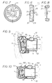
- the clamping device comprises a clamping jaw 10 comprising a plate 11 and a body 12; the plate 11 carries a support member 13 intended to cooperate with the face concave 2 of a puck 1 to overflow; with the convex face 3 of the puck 1 cooperates another jaw, not shown, fixed, centered, like the jaw of clamping 10, on the axis 4 of the puck 1, here its optical axis; as known per se, the fixed jaw, not shown, carries an elastic support member, of the kind suction cup, on which the puck 1 is "crushed" by the clamping jaw 10 by through its relatively elastic support member 13.
- the body 12 is hollow and provided with a blind housing 15 cylindrical, by means of which the clamping jaw 10 is mounted on the nose 6 of a spindle 5, of the overflow machine, centered on the axis 4; a screw 14 of the needle type screwed into a threaded hole 16 which crosses the wall of the body 12 allows the body 12 to be joined to the nose 6 of the spindle 5.
- the torque is transmitted by a radial pin not shown which is housed in a notch 34 of the body 12.
- the body 12 From its front transverse wall 17 which limits its blind housing cylindrical 15, the body 12 carries a male element 18 adapted to cooperate with a female housing 19 formed in the plate 11.
- the male element 18 is provided with facets 20, here six in number, regularly distributed around its axis 21; each facet 20 has a generally cylindrical shape whose generatrices extend orthogonally to said axis 21: thus, the two facets 20 opposite visible in section in Figure 2 have their generatrices perpendicular to the plane of the figure; the generators, and therefore each facet 20, extend on either side of the same transverse plane 22, advantageously symmetrically with respect to this plane 22; preferably their section through the plane of Figure 2 is in an arc centered on the axis at point 23 of intersection by the axis 21 of said transverse plane 22.
- the female housing 19 carries planar faces 24 parallel to the axis 25 that presents the plate 11; the female housing 19 carries as many faces 24, regularly distributed circumferentially, that there are 20 facets on the male element 18, each face 24 being intended to cooperate with each facet 20.
- the bottom 26 is of frustoconical shape, centered on the axis 25.
- the bottom 26 is of semi-spherical shape.
- the bottom 26 has a circular central opening 27 corresponding to the smaller diameter base when the bottom 26 is frustoconical shape.
- the plate 11 On its face intended to be opposite the puck 1 to overflow, the plate 11 has an annular recess 31 intended to receive the support member 13 made of semi-elastic material; more specifically, the support member 13 includes a web 33 surrounded by an annular crown 32 intended to be housed in the annular recess 31 of the plate 11; here the central opening 27 from the bottom 26 of the female housing 19 facilitates the positioning of the member support 13; alternatively, the bottom of the female housing 19 is full and the member support 13 has only the crown 32.
- the plate 11 and the body 12 are integral in rotation, by cooperation of the facets 20 with the faces 24; in addition, this cooperation allows the plate 11 to move angularly relative to the body 12: the support member 13 that the plate 11 can therefore be applied to the concave face 2 of the puck 1 which let the angle of the mean tangent of this face be, as shown in Figure 9; moreover, the cooperation of the facets 20 of the male element 18 with the bottom 26 of the female housing 19 ensures the transmission of the clamping force along axis 4 whatever the angle in question.
- the joint according to the invention functions in the manner of a ball joint while securing in rotation the male element 18 of the body 12 and the female housing 19 of the plate 11.
- the presence of six facets and six faces, arranged hexagonally, opposite two to two, allows a symmetrical swiveling from the point of view of the angles of movement of the plate 11 relative to the body 12; moreover, this hexagonal arrangement leads to an articulation having practically no rotating game and the cost of realization is reasonable; by comparing, an even number of facets and faces greater than six requires a play in very tight rotation, which strikes the cost price.
- variants are possible; a variant with three or five facets and three or five faces also works: the swiveling is easy around an axis parallel to the flat faces; elsewhere, the travel is limit ; however, the travel is not symmetrical depending on the direction of travel.
- a variant with four facets and four faces also works easily and symmetrically around an axis parallel to two parallel faces, elsewhere the travel being more limited.
- the joint is advantageously protected by an elastic bellows 30 rubber surrounding it, even chips made during the overflowing; one end of the bellows 30 is stapled in a groove 28 presented by the body 12 and the other end in a groove 29 of the plate 11; this bellows 30 is preferably mounted in tension between the plate 11 and the body 12; he thus assembles these two pieces of simple and easy to dismantle while permanently ensuring the contact of the male element 18 on the bottom 26 of the female housing 19, the joint is therefore without axial play; it should also be noted that, thanks at the bellows 30, upon loosening, the plate 11 and the body 12 resume automatically their starting position for which they are coaxial, as shown in figure 1.
- the clamping device 100 comprises a body 12 similar to that of the previous device 10, and a plate 111 of diameter lower than that of the previous plate 11; the tray 111 is provided with a support member 113 and a female housing 19 adapted to cooperate with the male element 18 of the body 12; a bellows 130 assembles the plate 111 and the body 12.
- the body 12 is designed to be mounted on pin 5 of the overflow machine; alternatively, this is the end of the pin 5 itself which is shaped like the body 12.
Landscapes
- Engineering & Computer Science (AREA)
- Mechanical Engineering (AREA)
- Chemical & Material Sciences (AREA)
- Ceramic Engineering (AREA)
- Inorganic Chemistry (AREA)
- Grinding And Polishing Of Tertiary Curved Surfaces And Surfaces With Complex Shapes (AREA)
- Jigs For Machine Tools (AREA)
- Eyeglasses (AREA)
- Re-Forming, After-Treatment, Cutting And Transporting Of Glass Products (AREA)
- Liquid Crystal (AREA)
Applications Claiming Priority (2)
| Application Number | Priority Date | Filing Date | Title |
|---|---|---|---|
| FR9813262 | 1998-10-22 | ||
| FR9813262A FR2784923B1 (fr) | 1998-10-22 | 1998-10-22 | Dispositif de serrage d'un palet sur une machine a deborder les verres optiques |
Publications (2)
| Publication Number | Publication Date |
|---|---|
| EP0995546A1 true EP0995546A1 (de) | 2000-04-26 |
| EP0995546B1 EP0995546B1 (de) | 2002-07-31 |
Family
ID=9531876
Family Applications (1)
| Application Number | Title | Priority Date | Filing Date |
|---|---|---|---|
| EP99402518A Expired - Lifetime EP0995546B1 (de) | 1998-10-22 | 1999-10-13 | Clamping device for fixing a blank on a spectacle lens edging machine |
Country Status (6)
| Country | Link |
|---|---|
| US (1) | US6231433B1 (de) |
| EP (1) | EP0995546B1 (de) |
| JP (1) | JP4526140B2 (de) |
| DE (1) | DE69902333T2 (de) |
| ES (1) | ES2181378T3 (de) |
| FR (1) | FR2784923B1 (de) |
Cited By (3)
| Publication number | Priority date | Publication date | Assignee | Title |
|---|---|---|---|---|
| EP1243381A2 (de) * | 2001-03-22 | 2002-09-25 | Loh Optikmaschinen AG | Anordnung zum Blocken und Spannen von am Rand zu bearbeitenden optischen Linsen, insbesondere Brillengläsern |
| US6984161B2 (en) | 2002-09-20 | 2006-01-10 | Kabushiki Kaisha Topcon | Lens grinding processing apparatus |
| CN103231308A (zh) * | 2013-03-29 | 2013-08-07 | 浙江恒成硬质合金有限公司 | 平顶件 |
Families Citing this family (3)
| Publication number | Priority date | Publication date | Assignee | Title |
|---|---|---|---|---|
| US7174432B2 (en) * | 2003-08-19 | 2007-02-06 | Nvidia Corporation | Asynchronous, independent and multiple process shared memory system in an adaptive computing architecture |
| KR101817497B1 (ko) | 2015-11-17 | 2018-01-11 | 주식회사 휴비츠 | 렌즈 클램핑 장치 |
| CN114935499B (zh) * | 2022-03-30 | 2023-07-07 | 荣耀终端有限公司 | 一种夹持装置和测试装置 |
Citations (4)
| Publication number | Priority date | Publication date | Assignee | Title |
|---|---|---|---|---|
| DE1947009A1 (de) * | 1969-09-17 | 1971-03-25 | Zeiss Carl Fa | Vorrichtung zum Halten von optischen Linsen bei der Randbearbeitung in Schleifmaschinen |
| FR2226824A5 (en) * | 1973-04-18 | 1974-11-15 | Asselin Ets | Soft jawed clamp gripping lenses - has inclinable jaw for clamping of prismatic lens for edge bevelling etc |
| GB1477126A (en) * | 1975-02-18 | 1977-06-22 | Wernicke & Co Gmbh | Spectacle lens holder with two coaxial lens holder half- shafts |
| JPS57201160A (en) * | 1981-06-05 | 1982-12-09 | Seiko Epson Corp | Back-up head chuck mechanism for eccentric lense machining unit |
Family Cites Families (8)
| Publication number | Priority date | Publication date | Assignee | Title |
|---|---|---|---|---|
| US1184496A (en) * | 1915-06-26 | 1916-05-23 | Bruno Berndt Stenvall | Grinding-fixture. |
| US2293291A (en) * | 1940-05-29 | 1942-08-18 | Gaspari & Co Inc J | Lens grinding machine |
| JPS4917015Y1 (de) * | 1969-03-17 | 1974-05-01 | ||
| FR2079496A5 (de) * | 1970-02-03 | 1971-11-12 | Lunetiers Ste | |
| JPH085001B2 (ja) * | 1988-01-09 | 1996-01-24 | 株式会社トプコン | 玉摺機 |
| DE4214266A1 (de) * | 1992-05-01 | 1993-11-04 | Loh Engineering Ag Oensingen | Vorrichtung zur fuehrung eines werkstuecks oder werkzeugs bei der bearbeitung torischer oder sphaerischer flaechen optischer linsen auf schleif- oder poliermaschinen |
| JPH106191A (ja) * | 1996-06-21 | 1998-01-13 | Sony Corp | 基板研削システム |
| JPH10156686A (ja) * | 1996-12-03 | 1998-06-16 | Fuji Photo Optical Co Ltd | 光学素材心出し用保持装置の保持圧調整装置 |
-
1998
- 1998-10-22 FR FR9813262A patent/FR2784923B1/fr not_active Expired - Lifetime
-
1999
- 1999-10-13 DE DE69902333T patent/DE69902333T2/de not_active Expired - Lifetime
- 1999-10-13 ES ES99402518T patent/ES2181378T3/es not_active Expired - Lifetime
- 1999-10-13 EP EP99402518A patent/EP0995546B1/de not_active Expired - Lifetime
- 1999-10-22 JP JP30108999A patent/JP4526140B2/ja not_active Expired - Lifetime
- 1999-10-22 US US09/425,062 patent/US6231433B1/en not_active Expired - Lifetime
Patent Citations (4)
| Publication number | Priority date | Publication date | Assignee | Title |
|---|---|---|---|---|
| DE1947009A1 (de) * | 1969-09-17 | 1971-03-25 | Zeiss Carl Fa | Vorrichtung zum Halten von optischen Linsen bei der Randbearbeitung in Schleifmaschinen |
| FR2226824A5 (en) * | 1973-04-18 | 1974-11-15 | Asselin Ets | Soft jawed clamp gripping lenses - has inclinable jaw for clamping of prismatic lens for edge bevelling etc |
| GB1477126A (en) * | 1975-02-18 | 1977-06-22 | Wernicke & Co Gmbh | Spectacle lens holder with two coaxial lens holder half- shafts |
| JPS57201160A (en) * | 1981-06-05 | 1982-12-09 | Seiko Epson Corp | Back-up head chuck mechanism for eccentric lense machining unit |
Non-Patent Citations (1)
| Title |
|---|
| PATENT ABSTRACTS OF JAPAN vol. 007, no. 055 (M - 198) 5 March 1983 (1983-03-05) * |
Cited By (5)
| Publication number | Priority date | Publication date | Assignee | Title |
|---|---|---|---|---|
| EP1243381A2 (de) * | 2001-03-22 | 2002-09-25 | Loh Optikmaschinen AG | Anordnung zum Blocken und Spannen von am Rand zu bearbeitenden optischen Linsen, insbesondere Brillengläsern |
| EP1243381A3 (de) * | 2001-03-22 | 2002-11-27 | Loh Optikmaschinen AG | Anordnung zum Blocken und Spannen von am Rand zu bearbeitenden optischen Linsen, insbesondere Brillengläsern |
| US6984161B2 (en) | 2002-09-20 | 2006-01-10 | Kabushiki Kaisha Topcon | Lens grinding processing apparatus |
| CN103231308A (zh) * | 2013-03-29 | 2013-08-07 | 浙江恒成硬质合金有限公司 | 平顶件 |
| CN103231308B (zh) * | 2013-03-29 | 2016-02-10 | 浙江恒成硬质合金有限公司 | 平顶件 |
Also Published As
| Publication number | Publication date |
|---|---|
| JP4526140B2 (ja) | 2010-08-18 |
| ES2181378T3 (es) | 2003-02-16 |
| DE69902333D1 (de) | 2002-09-05 |
| FR2784923A1 (fr) | 2000-04-28 |
| EP0995546B1 (de) | 2002-07-31 |
| US6231433B1 (en) | 2001-05-15 |
| DE69902333T2 (de) | 2003-04-17 |
| JP2000131657A (ja) | 2000-05-12 |
| FR2784923B1 (fr) | 2001-01-05 |
Similar Documents
| Publication | Publication Date | Title |
|---|---|---|
| EP1558160A1 (de) | Spannmutter für eine osteosynthesevorrichtung | |
| FR2572194A1 (fr) | Support de piece nasale de lunettes | |
| CA2472314C (fr) | Outil pour le surfacage d'une surface optique | |
| EP2699385B1 (de) | Halter für brillengläser | |
| EP0995546B1 (de) | Clamping device for fixing a blank on a spectacle lens edging machine | |
| CA2531960C (fr) | Outil pour le surfacage d'une surface optique | |
| FR2897697A1 (fr) | Monture d'optique. | |
| WO2000050782A1 (fr) | Joint de transmission homocinetique et organe de transmission mecanique pour un tel joint | |
| FR2606472A1 (fr) | Dispositif d'articulation entre deux pieces, notamment entre deux elements de mannequin | |
| EP0176397B1 (de) | Vorrichtung zum Orientieren eines optischen Elementes | |
| EP0296909A1 (de) | Vorrichtung zur vibrationslosen Übertragung von Bewegungen einer elektrischen Betätigung auf die Trägerplatte eines Rückspiegels | |
| EP1174061B1 (de) | Präsentationsvorrichtung für Brillengläser | |
| EP0932848A1 (de) | Verfahren zur verbindung eines bügels mit einer brillenfassung sowie brillenscharnier | |
| EP0337864A1 (de) | Brillengestell-Träger für eine Reproduzier-Maschine | |
| FR2732285A1 (fr) | Contacteur electrique tournant comprenant des moyens de detrompage au montage | |
| EP0403354B1 (de) | Führungsvorrichtung für ein mobiles Element parallel zu einer Achse und Instrument mit einer derartigen Führung | |
| EP0990934B1 (de) | Montagevorrichtung für ein in Richtung seiner Axe bewegbares optisches System | |
| FR2576134A1 (fr) | Dispositif pour fixer sur un support, de facon rapide et amovible, un appareil devant pouvoir etre oriente en site et en azimut | |
| FR2598127A1 (fr) | Dispositif de reglage de l'orientation du reflecteur d'un projecteur de vehicule automobile | |
| FR2574588A1 (fr) | " manche a balai " | |
| FR2631135A1 (fr) | Organe de support nasal pour lunettes | |
| FR2720009A1 (fr) | Manette de commande adaptable sur console de jeux électronique. | |
| FR2520822A1 (fr) | Joint homocinetique a mobilite angulaire | |
| FR2704331A1 (fr) | Mécanisme à crans pour un levier de manÓoeuvre. | |
| EP0175164A1 (de) | Vorrichtung um die axiale Position eines auf einer werkzeugmaschine zu bearbeitenden Werkstückes zu messen, insbesondere auf einer Schleifmaschine für äussere zylindrische Flächen |
Legal Events
| Date | Code | Title | Description |
|---|---|---|---|
| PUAI | Public reference made under article 153(3) epc to a published international application that has entered the european phase |
Free format text: ORIGINAL CODE: 0009012 |
|
| AK | Designated contracting states |
Kind code of ref document: A1 Designated state(s): BE DE ES GB IT |
|
| AX | Request for extension of the european patent |
Free format text: AL;LT;LV;MK;RO;SI |
|
| 17P | Request for examination filed |
Effective date: 20000519 |
|
| AKX | Designation fees paid |
Free format text: BE DE ES GB IT |
|
| GRAG | Despatch of communication of intention to grant |
Free format text: ORIGINAL CODE: EPIDOS AGRA |
|
| 17Q | First examination report despatched |
Effective date: 20011114 |
|
| GRAG | Despatch of communication of intention to grant |
Free format text: ORIGINAL CODE: EPIDOS AGRA |
|
| GRAH | Despatch of communication of intention to grant a patent |
Free format text: ORIGINAL CODE: EPIDOS IGRA |
|
| GRAH | Despatch of communication of intention to grant a patent |
Free format text: ORIGINAL CODE: EPIDOS IGRA |
|
| GRAA | (expected) grant |
Free format text: ORIGINAL CODE: 0009210 |
|
| AK | Designated contracting states |
Kind code of ref document: B1 Designated state(s): BE DE ES GB IT |
|
| REG | Reference to a national code |
Ref country code: GB Ref legal event code: FG4D Free format text: NOT ENGLISH |
|
| REF | Corresponds to: |
Ref document number: 69902333 Country of ref document: DE Date of ref document: 20020905 |
|
| GBT | Gb: translation of ep patent filed (gb section 77(6)(a)/1977) |
Effective date: 20020829 |
|
| REG | Reference to a national code |
Ref country code: ES Ref legal event code: FG2A Ref document number: 2181378 Country of ref document: ES Kind code of ref document: T3 |
|
| PLBE | No opposition filed within time limit |
Free format text: ORIGINAL CODE: 0009261 |
|
| STAA | Information on the status of an ep patent application or granted ep patent |
Free format text: STATUS: NO OPPOSITION FILED WITHIN TIME LIMIT |
|
| 26N | No opposition filed |
Effective date: 20030506 |
|
| PGFP | Annual fee paid to national office [announced via postgrant information from national office to epo] |
Ref country code: BE Payment date: 20031015 Year of fee payment: 5 |
|
| PG25 | Lapsed in a contracting state [announced via postgrant information from national office to epo] |
Ref country code: BE Free format text: LAPSE BECAUSE OF NON-PAYMENT OF DUE FEES Effective date: 20041031 |
|
| BERE | Be: lapsed |
Owner name: *ESSILOR INTERNATIONAL CIE GENERALE D'OPTIQUE Effective date: 20041031 |
|
| PG25 | Lapsed in a contracting state [announced via postgrant information from national office to epo] |
Ref country code: IT Free format text: LAPSE BECAUSE OF NON-PAYMENT OF DUE FEES;WARNING: LAPSES OF ITALIAN PATENTS WITH EFFECTIVE DATE BEFORE 2007 MAY HAVE OCCURRED AT ANY TIME BEFORE 2007. THE CORRECT EFFECTIVE DATE MAY BE DIFFERENT FROM THE ONE RECORDED. Effective date: 20051013 |
|
| BERE | Be: lapsed |
Owner name: *ESSILOR INTERNATIONAL CIE GENERALE D'OPTIQUE Effective date: 20041031 |
|
| PGFP | Annual fee paid to national office [announced via postgrant information from national office to epo] |
Ref country code: ES Payment date: 20081127 Year of fee payment: 10 |
|
| PGFP | Annual fee paid to national office [announced via postgrant information from national office to epo] |
Ref country code: GB Payment date: 20081016 Year of fee payment: 10 |
|
| PG25 | Lapsed in a contracting state [announced via postgrant information from national office to epo] |
Ref country code: GB Free format text: LAPSE BECAUSE OF NON-PAYMENT OF DUE FEES Effective date: 20091013 |
|
| REG | Reference to a national code |
Ref country code: ES Ref legal event code: FD2A Effective date: 20110324 |
|
| PG25 | Lapsed in a contracting state [announced via postgrant information from national office to epo] |
Ref country code: ES Free format text: LAPSE BECAUSE OF NON-PAYMENT OF DUE FEES Effective date: 20110310 |
|
| PG25 | Lapsed in a contracting state [announced via postgrant information from national office to epo] |
Ref country code: ES Free format text: LAPSE BECAUSE OF NON-PAYMENT OF DUE FEES Effective date: 20091014 |
|
| REG | Reference to a national code |
Ref country code: DE Ref legal event code: R082 Ref document number: 69902333 Country of ref document: DE Representative=s name: 24IP LAW GROUP SONNENBERG FORTMANN, DE Ref country code: DE Ref legal event code: R081 Ref document number: 69902333 Country of ref document: DE Owner name: ESSILOR INTERNATIONAL, FR Free format text: FORMER OWNER: ESSILOR INTERNATIONAL (COMPAGNIE GENERALE D'OPTIQUE), CHARENTON-LE-PONT, FR |
|
| PGFP | Annual fee paid to national office [announced via postgrant information from national office to epo] |
Ref country code: DE Payment date: 20181029 Year of fee payment: 20 |
|
| REG | Reference to a national code |
Ref country code: DE Ref legal event code: R071 Ref document number: 69902333 Country of ref document: DE |
|
| P01 | Opt-out of the competence of the unified patent court (upc) registered |
Effective date: 20230525 |