EP0989729A2 - Bildeingabesystem, Steuerverfahren dafür und Speichermedium - Google Patents
Bildeingabesystem, Steuerverfahren dafür und Speichermedium Download PDFInfo
- Publication number
- EP0989729A2 EP0989729A2 EP99118642A EP99118642A EP0989729A2 EP 0989729 A2 EP0989729 A2 EP 0989729A2 EP 99118642 A EP99118642 A EP 99118642A EP 99118642 A EP99118642 A EP 99118642A EP 0989729 A2 EP0989729 A2 EP 0989729A2
- Authority
- EP
- European Patent Office
- Prior art keywords
- image input
- input device
- computer
- software
- image
- Prior art date
- Legal status (The legal status is an assumption and is not a legal conclusion. Google has not performed a legal analysis and makes no representation as to the accuracy of the status listed.)
- Granted
Links
Images


Classifications
-
- H—ELECTRICITY
- H04—ELECTRIC COMMUNICATION TECHNIQUE
- H04N—PICTORIAL COMMUNICATION, e.g. TELEVISION
- H04N1/00—Scanning, transmission or reproduction of documents or the like, e.g. facsimile transmission; Details thereof
- H04N1/00127—Connection or combination of a still picture apparatus with another apparatus, e.g. for storage, processing or transmission of still picture signals or of information associated with a still picture
- H04N1/00204—Connection or combination of a still picture apparatus with another apparatus, e.g. for storage, processing or transmission of still picture signals or of information associated with a still picture with a digital computer or a digital computer system, e.g. an internet server
-
- H—ELECTRICITY
- H04—ELECTRIC COMMUNICATION TECHNIQUE
- H04N—PICTORIAL COMMUNICATION, e.g. TELEVISION
- H04N2201/00—Indexing scheme relating to scanning, transmission or reproduction of documents or the like, and to details thereof
- H04N2201/0008—Connection or combination of a still picture apparatus with another apparatus
- H04N2201/0013—Arrangements for the control of the connected apparatus by the still picture apparatus
Definitions
- the present invention relates to a system which connects an image input device such as a digital camera having a plurality of operation modes, and an image processing apparatus such as a personal computer or the like, and inputs and saves images, its control method, and a storage medium.
- an image input device such as a digital camera having a plurality of operation modes
- an image processing apparatus such as a personal computer or the like
- an RS-232C serial cable is prevalently used as an I/F for connecting a personal computer and camera.
- This I/F has high compatibility, i.e., is supported by all personal computers, but has low transfer rate.
- image input software such as a TWAIN driver or the like has a fixed procedure for transferring thumbnail data with a small data size first to display image indices in the camera, and then transferring only original images selected by the user.
- USB Universal Serial Bus
- STI Silicon Image Captures Architecture and Interfaces
- USB can implement hot plugin (a USB device can be plugged or unplugged while a PC is running, and the OS can recognize the plugged or unplugged state), and a mechanism for automatically recognizing the connected camera, and automatically starting a predetermined application associated with the camera by the STI can be provided.
- hot plugin a USB device can be plugged or unplugged while a PC is running, and the OS can recognize the plugged or unplugged state
- a mechanism for automatically recognizing the connected camera, and automatically starting a predetermined application associated with the camera by the STI can be provided.
- the STI has a mechanism for starting corresponding PC software in response to connection of a camera as a trigger. Hence, tedious operation can be greatly reduced, and it is easy even for a novice user of the personal computer to use such system.
- the STI architecture considers the TWAIN driver as main image input software, and suffers the following shortcomings:
- the digital camera has not only a function of sensing an image, playing back the sensed image on its LCD, and transferring the image to the PC, but also more functions.
- the number of functions of the digital camera is increasing. For example, the following functions falling outside the range of a function of merely capturing a sensed image into a PC are available:
- the present invention has been made in consideration of the above-mentioned problems, and has as its object to provide an image input system which is easy to use, its control method, and a storage medium.
- an image input system is characterized by the following arrangement according to its first aspect.
- an image input system comprising an image input device having a plurality of operation modes, and a computer having a plurality of software programs corresponding to the plurality of operation modes, wherein when the image input device is connected to the computer, when a power supply of the image input device is turned on after the image input device is connected to the computer, or when the image input device is switched to another operation mode while the image input device is connected to the computer, the software program corresponding to the operation mode of the image input device is automatically started.
- An image input system is characterized by the following arrangement according to its second aspect.
- an image input system comprising an image input device having a plurality of operation modes, and a computer having a single software program which has a plurality of modes corresponding to the plurality of operation modes, wherein when the image input device is connected to the computer, when a power supply of the image input device is turned on after the image input device is connected to the computer, or when the image input device is switched to another operation mode while the image input device is connected to the computer, that one of the plurality of modes of the software in the computer, which corresponds to the operation mode of the image input device, is automatically started.
- a method of controlling an image input system according to the present invention is characterized by the following arrangement according to its first aspect.
- a method of controlling an image input system which comprises an image input device having a plurality of operation modes, and a computer having a plurality of software programs corresponding to the plurality of operation modes, comprising the step of automatically starting the software program corresponding to the operation mode of the image input device, when the image input device is connected to the computer, when a power supply of the image input device is turned on after the image input device is connected to the computer, or when the image input device is switched to another operation mode while the image input device is connected to the computer.
- a method of controlling an image input system according to the present invention is characterized by the following arrangement according to its second aspect.
- a method of controlling an image input system which comprises an image input device having a plurality of operation modes, and a computer having a single software program which has a plurality of modes corresponding to the plurality of operation modes, comprising the step of automatically starting that one of the plurality of modes of the software in the computer, which corresponds to the operation mode of the image input device when the image input device is connected to the computer, when a power supply of the image input device is turned on after the image input device is connected to the computer, or when the image input device is switched to another operation mode while the image input device is connected to the computer.
- a storage medium according to the present invention is characterized by the following arrangement according to its first aspect.
- a storage medium that stores a control program for controlling an image input system, which comprises an image input device having a plurality of operation modes, and a computer having a plurality of software programs corresponding to the plurality of operation modes, the control program comprising a code of the step of automatically starting the software program corresponding to the operation mode of the image input device, when the image input device is connected to the computer, when a power supply of the image input device is turned on after the image input device is connected to the computer, or when the image input device is switched to another operation mode while the image input device is connected to the computer.
- a storage medium according to the present invention is characterized by the following arrangement according to its second aspect.
- a storage medium that stores a control program for controlling an image input system, which comprises an image input device having a plurality of operation modes, and a computer having a single software program which has a plurality of modes corresponding to the plurality of operation modes, the control program comprising a code of the step of automatically starting that one of the plurality of modes of the software in the computer, which corresponds to the operation mode of the image input device when the image input device is connected to the computer, when a power supply of the image input device is turned on after the image input device is connected to the computer, or when the image input device is switched to another operation mode while the image input device is connected to the computer.
- an application corresponding to the mode set in the camera is started, is connected to the camera, and automatically executes a predetermined process.
- the application is automatically disconnected from the camera, and automatically ends depending on its type or setups, and an application corresponding to the selected mode is started and is connected to the camera to execute predetermined operation.
- the mode includes the image sensing mode, playback mode, slideshow mode, stitch assist mode, and the like, that have already been described in the paragraphs of the prior art, and these modes can be set using a mode dial switch and push switches of the camera main body, menu items displayed on an LCD panel of the camera, and the like.
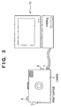
- Fig. 1 shows a digital camera used in the first embodiment.
- reference numeral 1 denotes a USB I/F which is connected to the PC.
- Reference numeral 2 denotes a mode dial switch which has a playback (Play) mode 2a, image sensing (Rec) mode 2b, stitch assist (Stitch) mode 2c, slideshow playback (Slide) mode 2d, and power OFF 2e.
- Reference numeral 3 denotes a CF (Compact FlashTM) card slot.
- the selected mode is started simultaneously.
- a preview image is displayed on an LCD 4, and an image is sensed by pressing a release switch 5 and is stored in a CF card 6.
- the latest sensed and recorded image is displayed on the LCD 4, and other recorded images are played back in turn by + and - buttons 7a and 7b.
- the already sensed image is displayed on one side 4a of the LCD 4, and a preview image is displayed on the other side 4b and can be sensed.
- images recorded in the camera are played back on the LCD 4 or on a TV via a video output 8 at predetermined time intervals.
- the displayed image can be switched to the next or previous one using the + and - buttons 7a and 7b.
- Fig. 3 shows a state wherein the camera and PC are connected via USB.
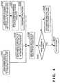
- the camera is connected to the PC and can communicate with it in three states shown in Fig. 4.
- the camera is connected to the PC via USB while its power switch is ON and a given mode is selected (a mode set by the setting position of, e.g., the mode dial switch) (step S401).
- a given mode is selected (a mode set by the setting position of, e.g., the mode dial switch) (step S401).
- the camera sends a message indicating the mode in which the camera is set currently to the PC at a timing that it detects connection to USB (step S406).
- the camera is connected to USB while its power switch is OFF, and after that, the power switch is turned on. At this time, the camera also sends a message indicating the mode in which the camera is set currently to the PC in accordance with the set mode (step S406).
- the camera has already been set in a given mode, the corresponding application has already been started, and the camera and application are connected and communicate with each other.
- the camera sends a disconnection message to the connected application at that timing to disconnect the communication with the application (step S405).
- a message indicating a new mode in which the camera is set currently is sent to the PC (step S406).
- the camera checks if sensed images are present in the camera (step S407). If no images are present, the camera also sends a message indicating that no images are present in the camera (step S408).
- the aforementioned process is executed first when the camera and PC are connected, and an associated application is started.
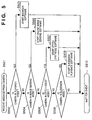
- the STI starts an associated application in correspondence with the message of each mode.
- Fig. 5 shows this process.
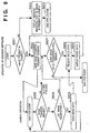
- Fig. 6 shows operation automatically executed when the browser software associated with the playback mode is started.
- step S601 It is checked in step S601 if images are present in the camera. This checking step is attained by checking if the message issued in step S408 in Fig. 4 has arrived at the PC. If this message has arrived, the browser software displays a message indicating no image (step S602), and ends itself (step S603).
- the browser software sends an image transfer request to the camera in step S604.
- the camera checks if the received message is an image transfer request (step S605), and then checks if all images have already been transferred (step S606). If images to be transferred still remain, the camera sends image data to the browser software in step S608.
- the browser software receives the image data in step S609, and displays that image data on the PC screen in step S610.
- all image data in the camera can be automatically loaded from the camera and can be displayed on the PC. From the viewpoint of user operation, all images in the camera can be automatically displayed on the PC by only setting the mode dial switch 2 at the playback mode 2a.
- the camera sends a corresponding message to the browser software.
- the browser software executes a process for disconnecting the communication with the camera, and then executes one of the following three options.
- the first option automatically ends the browser software
- the second option displays a message indicating that the connection with the camera is disconnected by user operation to the user, and prompts the user to select whether the browser software is to end or continue
- the third option continues to run the browser software.
- These options can be selected from a setup menu of the browser software.
- the second option that prompts the user to select whether the browser software is to end or continue is preferably set.
- FIG. 8 shows an example of the on-line image sensing software.
- An image which is being currently seen by the camera is displayed on a preview area 802 in a window 801 as a preview image.
- the camera senses the image, and sensed image data is displayed on a window 804.
- the sensed image data can be saved as an image file.
- Fig. 7 is a flow chart showing operation executed when the on-line image sensing software is started.
- the on-line image sensing software When the mode dial switch 2 is set at the Rec mode 2b, the on-line image sensing software is automatically started.
- the on-line image sensing software sends a reduced-scale image transmission request to the camera (step S701).
- This reduced-scale image is to be displayed on the preview area 802.
- a reduced-scale image is requested in place of a full-size image which is equal to the sensed image size.
- step S703 the camera sends reduced-scale image data (step S703).
- the on-line image sensing software receives that image data in step S704. and displays the received data on the preview area 802 in step S705.
- a preview image which is being currently sensed by the camera is displayed as a moving image on the preview area 802.
- step S707 When the user has pressed the image sensing button 803, the control leaves the loop based on the checking result in step S706, and a sensed image transfer request is sent in step S707.
- the camera Upon receiving this message (step S708), the camera senses an image, and sends sensed full-size image data in step S709.
- the on-line image sensing software receives this image data in step S710, and displays it on the window 804 in Fig. 8 in step S711.
- the user can automatically preview an image on-line by only setting the mode dial switch 2 at the Rec mode 2b, and can sense that image by pressing the image sensing button on the PC.
- the camera sends a corresponding message to the on-line image sensing software.
- the on-line image sensing software executes a process for disconnecting the communication with the camera, and then automatically ends itself.
- the aforementioned browser software has options for selecting, e.g., whether or not the software continues to run, but such options are not available for this software. This is because the on-line image sensing software does not function at all unless it is connected to the camera.
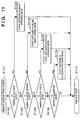
- step S901 It is checked in step S901 if images are present in the camera. This checking step is attained by checking if the message issued in step S408 in Fig. 4 has arrived at the PC. If this message has arrived, the stitch synthesis software displays a message indicating that no images are stored in the camera (step S902), and ends (step S903).
- the stitch synthesis software sends a transfer request of images sensed in the stitch assist mode to the camera in step S904. Upon receiving this request, the camera checks if all stitch assist images have already been transferred (step S905). If stitch assist image to be transferred still remain, image data is transferred to the stitch synthesis software in step S907.
- the stitch synthesis software receives this image data in step S908, and saves that image data in a file in step S909. By repeating these steps, all stitch assist image data in the camera can be automatically loaded from the camera. After that, the saved stitch assist images are read out, and a process for stitching these images to obtain a single synthesis image is executed in step S910.
- images can be sensed in the stitch assist mode by setting the mode dial switch 2 at the stitch assist mode 2c, and all the stitch assist images in the camera can be automatically loaded into the PC and can be synthesized by only connecting the camera to the PC.
- the camera sends a corresponding message to the stitch synthesis software.
- the stitch synthesis software disconnects the connection with the camera. In this case, if all the stitch assist images in the camera have already been loaded, the stitch synthesis software continues a synthesis process. However, if all the images have not been loaded yet, the stitch synthesis software automatically ends itself since it cannot execute a synthesis process.
- step S1001 It is checked in step S1001 if images are present in the camera. This checking step is attained by checking if the message issued in step S408 in Fig. 4 has arrived at the PC. If this message has arrived, the slideshow playback software displays a message indicating that no images are stored in the camera (step S1002), and ends itself (step S1003).
- the slideshow playback software sends an image transfer request to the camera in step S1004.
- the camera checks if all images have already been transferred (step S1005).
- image data is sent to the slideshow playback software in step S1007.
- the slideshow playback software receives the image data in step S1008, and saves that image data in a file in step S1009.
- step S1010 all image data in the camera can be loaded from the camera. After that, the saved images are read out, and slideshow playback of these images is executed on the PC screen in step S1010.
- all images in the camera can be automatically loaded and can be played back as a slideshow by only setting the mode dial switch 2 at the slideshow mode 2d.
- the camera sends a corresponding message to the slideshow playback software.
- the slideshow playback software disconnects the connection with the camera. In this case, if all the images in the camera have already been loaded, the slideshow playback software continues slideshow playback. However, if all the images have not been loaded yet, the slideshow playback software automatically ends itself since it cannot execute slideshow playback.
- different software programs are started in correspondence with the operation modes of the camera.
- a single software program is started in an operation mode corresponding to the operation mode of the camera.
- the software is started in different modes in correspondence with the operation modes of the camera.
- step S1102 If it is determined in step S1102 that the camera is in the playback mode, the software is started in an image browsing mode in step S1103.
- the subsequent operation is the same as that described in the first embodiment.
- step S1104 If it is determined in step S1104 that the camera is in the image sensing mode, the software is started in an on-line image sensing mode in step S1105.
- the subsequent operation is the same as that described in the first embodiment.
- step S1106 If it is determined in step S1106 that the camera is in the stitch assist mode, the software is started in a stitch synthesis mode in step S1107.
- the subsequent operation is the same as that described in the first embodiment.
- step S1108 If it is determined in step S1108 that the camera is in the slideshow mode, the software is started in a slideshow playback mode in step S1109.
- the subsequent operation is the same as that described in the first embodiment.
- the objects of the present invention are also achieved by supplying a storage medium, which records a program code of a software program that can implement the functions of the above-mentioned embodiments to the system or apparatus, and reading out and executing the program code stored in the storage medium by a computer (or a CPU or MPU) of the system or apparatus.
- the program code itself read out from the storage medium implements the functions of the above-mentioned embodiments, and the storage medium which stores the program code constitutes the present invention.
- the storage medium for supplying the program code for example, a floppy disk, hard disk, optical disk, magneto-optical disk, CD-ROM, CD-R, magnetic tape, nonvolatile memory card, ROM, and the like may be used.
- the functions of the above-mentioned embodiments may be implemented not only by executing the readout program code by the computer but also by some or all of actual processing operations executed by an OS (operating system) running on the computer on the basis of an instruction of the program code.
- OS operating system
- the functions of the above-mentioned embodiments may be implemented by some or all of actual processing operations executed by a CPU or the like arranged in a function extension board or a function extension unit, which is inserted in or connected to the computer, after the program code read out from the storage medium is written in a memory of the extension board or unit.
- a software program can be automatically started in correspondence with the mode set in the camera.
- a software program can be started in a software mode corresponding to the mode set in the camera.
- an image input system has an image input device (camera) having a plurality of operation modes, and a computer having a plurality of software programs corresponding to the plurality of operation modes, and when the image input device is connected to the computer, when a power supply of the image input device is turned on after the image input device is connected to the computer, or when the image input device is switched to another operation mode while the image input device is connected to the computer, the software program corresponding to the operation mode of the image input device is automatically started.
- an image input device camera
- a computer having a plurality of software programs corresponding to the plurality of operation modes
Landscapes
- Engineering & Computer Science (AREA)
- Computing Systems (AREA)
- General Engineering & Computer Science (AREA)
- Multimedia (AREA)
- Signal Processing (AREA)
- Studio Devices (AREA)
- Processing Or Creating Images (AREA)
- Image Input (AREA)
Applications Claiming Priority (2)
| Application Number | Priority Date | Filing Date | Title |
|---|---|---|---|
| JP10268606A JP2000099697A (ja) | 1998-09-22 | 1998-09-22 | 画像入力システム及びその制御方法及び記憶媒体 |
| JP26860698 | 1998-09-22 |
Publications (3)
| Publication Number | Publication Date |
|---|---|
| EP0989729A2 true EP0989729A2 (de) | 2000-03-29 |
| EP0989729A3 EP0989729A3 (de) | 2001-02-28 |
| EP0989729B1 EP0989729B1 (de) | 2014-02-26 |
Family
ID=17460883
Family Applications (1)
| Application Number | Title | Priority Date | Filing Date |
|---|---|---|---|
| EP99118642.0A Expired - Lifetime EP0989729B1 (de) | 1998-09-22 | 1999-09-21 | Bildeingabesystem, Steuerverfahren dafür und Speichermedium |
Country Status (3)
| Country | Link |
|---|---|
| US (1) | US7701483B1 (de) |
| EP (1) | EP0989729B1 (de) |
| JP (1) | JP2000099697A (de) |
Cited By (2)
| Publication number | Priority date | Publication date | Assignee | Title |
|---|---|---|---|---|
| EP1229718A2 (de) * | 2001-02-02 | 2002-08-07 | Matsushita Graphic Communication Systems, Inc. | Netzwerkabtaster und Dateiübertragungs/empfangssystem und Benutzerendgerät und Dateiübertragungs/empfangsverfahren |
| EP1562362A1 (de) * | 2004-02-05 | 2005-08-10 | Aiptek International Inc. | Elektronisches Gerät mit Gastfunktion |
Families Citing this family (13)
| Publication number | Priority date | Publication date | Assignee | Title |
|---|---|---|---|---|
| JP4182464B2 (ja) | 2001-02-09 | 2008-11-19 | 富士フイルム株式会社 | ビデオ会議システム |
| US7522306B2 (en) | 2004-02-11 | 2009-04-21 | Hewlett-Packard Development Company, L.P. | Method and apparatus for generating a calibration target on a medium |
| US7894854B2 (en) * | 2004-10-26 | 2011-02-22 | Pantech & Curitel Communications, Inc. | Image/audio playback device of mobile communication terminal |
| JP4936504B2 (ja) * | 2005-09-26 | 2012-05-23 | キヤノン株式会社 | クレードル装置と操作端末とのそのプログラム、及びカメラシステム |
| US8224770B2 (en) * | 2005-12-02 | 2012-07-17 | Goldman, Sachs & Co. | Methods of operating computer system with data availability management software |
| JP4899646B2 (ja) * | 2006-06-02 | 2012-03-21 | 富士ゼロックス株式会社 | 画像形成システム |
| JP4989350B2 (ja) | 2007-08-06 | 2012-08-01 | キヤノン株式会社 | アダプタおよびその制御方法 |
| US20090115789A1 (en) * | 2007-11-07 | 2009-05-07 | Digi International Inc. | Methods, systems and apparatus for maximum frame size |
| US20090182904A1 (en) * | 2008-01-10 | 2009-07-16 | Sony Corporation | System and Method for Providing Peripheral Device Functionality |
| JP5393199B2 (ja) * | 2009-03-02 | 2014-01-22 | キヤノン株式会社 | 起動制御方法及び装置 |
| JP5348256B2 (ja) * | 2012-01-13 | 2013-11-20 | カシオ計算機株式会社 | データ処理装置、およびプログラム |
| US9137428B2 (en) * | 2012-06-01 | 2015-09-15 | Microsoft Technology Licensing, Llc | Storyboards for capturing images |
| US20140173442A1 (en) * | 2012-12-18 | 2014-06-19 | Microsoft Corporation | Presenter view in presentation application |
Citations (2)
| Publication number | Priority date | Publication date | Assignee | Title |
|---|---|---|---|---|
| EP0848548A2 (de) | 1996-12-10 | 1998-06-17 | Canon Kabushiki Kaisha | Kamera, Kameraanschlussvorrichtung und Kamerasystem |
| EP0860978A2 (de) | 1997-02-21 | 1998-08-26 | Canon Kabushiki Kaisha | System mit Datenverarbeitungs- und Dateneingabevorrichtung sowie Verfahren zu dessen Steuerung |
Family Cites Families (12)
| Publication number | Priority date | Publication date | Assignee | Title |
|---|---|---|---|---|
| US5563722A (en) * | 1992-02-26 | 1996-10-08 | Norris; Christopher | Method and apparatus for assembling a photographic album |
| JP2925417B2 (ja) | 1992-12-03 | 1999-07-28 | キヤノン株式会社 | 画像処理システム及び情報処理装置及び撮像装置と接続可能な外部装置 |
| JPH07131746A (ja) * | 1993-10-29 | 1995-05-19 | Canon Inc | 電子カメラ |
| JPH099014A (ja) | 1995-06-22 | 1997-01-10 | Casio Comput Co Ltd | エリアイメージセンサ付き画像処理装置 |
| JPH0998376A (ja) | 1995-07-27 | 1997-04-08 | Casio Comput Co Ltd | 電子撮像装置 |
| JPH0998325A (ja) | 1995-10-03 | 1997-04-08 | Canon Inc | 撮像装置及び画像処理装置 |
| JPH09163209A (ja) | 1995-12-08 | 1997-06-20 | Canon Inc | デジタルカメラ,撮像装置,および撮像手段制御装置 |
| US5848420A (en) * | 1996-06-14 | 1998-12-08 | Eastman Kodak Company | System and method for accessing data of a digital camera from a personal computer |
| US6459451B2 (en) * | 1996-06-24 | 2002-10-01 | Be Here Corporation | Method and apparatus for a panoramic camera to capture a 360 degree image |
| US6005613A (en) * | 1996-09-12 | 1999-12-21 | Eastman Kodak Company | Multi-mode digital camera with computer interface using data packets combining image and mode data |
| JP3690024B2 (ja) * | 1996-12-25 | 2005-08-31 | カシオ計算機株式会社 | 印刷装置及び印刷装置を使用する撮像画像印刷方式 |
| US6373507B1 (en) * | 1998-09-14 | 2002-04-16 | Microsoft Corporation | Computer-implemented image acquistion system |
-
1998
- 1998-09-22 JP JP10268606A patent/JP2000099697A/ja active Pending
-
1999
- 1999-09-21 US US09/400,154 patent/US7701483B1/en not_active Expired - Fee Related
- 1999-09-21 EP EP99118642.0A patent/EP0989729B1/de not_active Expired - Lifetime
Patent Citations (2)
| Publication number | Priority date | Publication date | Assignee | Title |
|---|---|---|---|---|
| EP0848548A2 (de) | 1996-12-10 | 1998-06-17 | Canon Kabushiki Kaisha | Kamera, Kameraanschlussvorrichtung und Kamerasystem |
| EP0860978A2 (de) | 1997-02-21 | 1998-08-26 | Canon Kabushiki Kaisha | System mit Datenverarbeitungs- und Dateneingabevorrichtung sowie Verfahren zu dessen Steuerung |
Cited By (4)
| Publication number | Priority date | Publication date | Assignee | Title |
|---|---|---|---|---|
| EP1229718A2 (de) * | 2001-02-02 | 2002-08-07 | Matsushita Graphic Communication Systems, Inc. | Netzwerkabtaster und Dateiübertragungs/empfangssystem und Benutzerendgerät und Dateiübertragungs/empfangsverfahren |
| EP1229718A3 (de) * | 2001-02-02 | 2005-01-26 | Panasonic Communications Co., Ltd. | Netzwerkabtaster und Dateiübertragungs/empfangssystem und Benutzerendgerät und Dateiübertragungs/empfangsverfahren |
| US7383328B2 (en) | 2001-02-02 | 2008-06-03 | Panasonic Communications Co., Ltd. | Terminal apparatus, network system and communication method including opening of received document file |
| EP1562362A1 (de) * | 2004-02-05 | 2005-08-10 | Aiptek International Inc. | Elektronisches Gerät mit Gastfunktion |
Also Published As
| Publication number | Publication date |
|---|---|
| EP0989729B1 (de) | 2014-02-26 |
| JP2000099697A (ja) | 2000-04-07 |
| US7701483B1 (en) | 2010-04-20 |
| EP0989729A3 (de) | 2001-02-28 |
Similar Documents
| Publication | Publication Date | Title |
|---|---|---|
| EP0989729B1 (de) | Bildeingabesystem, Steuerverfahren dafür und Speichermedium | |
| US6122003A (en) | Method and apparatus for changing operating modes of an image capture device | |
| US6507363B1 (en) | Method and system for automatically generating a plurality of folders for multiple devices and multiple sessions in a digital camera | |
| JP3862502B2 (ja) | デジタル画像撮像装置のための方法及びシステム | |
| US7228061B2 (en) | Image display system, image reproducing apparatus, digital television apparatus, image display method, and storage medium for controlling image display based on additional information read from multiple image recording apparatuses | |
| US8120674B2 (en) | Imaging apparatus | |
| US20040070675A1 (en) | System and method of processing a digital image for intuitive viewing | |
| JP2001326885A (ja) | 画像処理装置、画像処理方法、記憶媒体 | |
| EP0928098B1 (de) | Bildaufnahmeverfahren und Vorrichtung zum Verketten der Bilder | |
| JP2002505492A (ja) | 電子画像装置における機能を動的に更新するシステムおよび方法 | |
| US20050134689A1 (en) | Image processing system | |
| US20030193578A1 (en) | System and method for capturing and grouping motion video segments | |
| JP2002158948A (ja) | 画像表示システム、画像再生装置、画像表示方法および記憶媒体 | |
| JPH10108005A (ja) | 印刷装置及びその印刷システム | |
| JP2002305677A (ja) | ディジタルカメラ | |
| JP2001333363A (ja) | 情報通信装置、情報通信システム及び情報通信方法 | |
| JP4579397B2 (ja) | 画像閲覧装置、画像閲覧装置の制御方法及び記録媒体 | |
| JP3721927B2 (ja) | デジタルカメラ及び記録媒体 | |
| JP3419828B2 (ja) | 画像通信アダプター装置 | |
| JP2000333119A (ja) | 情報処理装置、情報処理システム、動作制御方法、及び記憶媒体 | |
| JP2000339344A (ja) | 画像読取保存装置 | |
| JP2004200997A (ja) | 情報処理装置 | |
| CN113261302B (zh) | 电子装置 | |
| JP2001069455A (ja) | 画像処理装置、画像処理方法及び記憶媒体 | |
| JP3636209B2 (ja) | 電子カメラシステム |
Legal Events
| Date | Code | Title | Description |
|---|---|---|---|
| PUAI | Public reference made under article 153(3) epc to a published international application that has entered the european phase |
Free format text: ORIGINAL CODE: 0009012 |
|
| AK | Designated contracting states |
Kind code of ref document: A2 Designated state(s): DE FR GB IT NL |
|
| AX | Request for extension of the european patent |
Free format text: AL;LT;LV;MK;RO;SI |
|
| PUAL | Search report despatched |
Free format text: ORIGINAL CODE: 0009013 |
|
| AK | Designated contracting states |
Kind code of ref document: A3 Designated state(s): AT BE CH CY DE DK ES FI FR GB GR IE IT LI LU MC NL PT SE |
|
| AX | Request for extension of the european patent |
Free format text: AL;LT;LV;MK;RO;SI |
|
| 17P | Request for examination filed |
Effective date: 20010710 |
|
| AKX | Designation fees paid |
Free format text: DE FR GB IT NL |
|
| GRAP | Despatch of communication of intention to grant a patent |
Free format text: ORIGINAL CODE: EPIDOSNIGR1 |
|
| GRAJ | Information related to disapproval of communication of intention to grant by the applicant or resumption of examination proceedings by the epo deleted |
Free format text: ORIGINAL CODE: EPIDOSDIGR1 |
|
| INTG | Intention to grant announced |
Effective date: 20130708 |
|
| GRAJ | Information related to disapproval of communication of intention to grant by the applicant or resumption of examination proceedings by the epo deleted |
Free format text: ORIGINAL CODE: EPIDOSDIGR1 |
|
| GRAP | Despatch of communication of intention to grant a patent |
Free format text: ORIGINAL CODE: EPIDOSNIGR1 |
|
| INTC | Intention to grant announced (deleted) | ||
| GRAP | Despatch of communication of intention to grant a patent |
Free format text: ORIGINAL CODE: EPIDOSNIGR1 |
|
| GRAS | Grant fee paid |
Free format text: ORIGINAL CODE: EPIDOSNIGR3 |
|
| GRAA | (expected) grant |
Free format text: ORIGINAL CODE: 0009210 |
|
| INTG | Intention to grant announced |
Effective date: 20130904 |
|
| AK | Designated contracting states |
Kind code of ref document: B1 Designated state(s): DE FR GB IT NL |
|
| REG | Reference to a national code |
Ref country code: GB Ref legal event code: FG4D |
|
| REG | Reference to a national code |
Ref country code: DE Ref legal event code: R096 Ref document number: 69945010 Country of ref document: DE Effective date: 20140403 |
|
| PGFP | Annual fee paid to national office [announced via postgrant information from national office to epo] |
Ref country code: FR Payment date: 20140307 Year of fee payment: 16 |
|
| REG | Reference to a national code |
Ref country code: NL Ref legal event code: VDEP Effective date: 20140226 |
|
| PG25 | Lapsed in a contracting state [announced via postgrant information from national office to epo] |
Ref country code: NL Free format text: LAPSE BECAUSE OF FAILURE TO SUBMIT A TRANSLATION OF THE DESCRIPTION OR TO PAY THE FEE WITHIN THE PRESCRIBED TIME-LIMIT Effective date: 20140226 |
|
| REG | Reference to a national code |
Ref country code: DE Ref legal event code: R097 Ref document number: 69945010 Country of ref document: DE |
|
| PLBE | No opposition filed within time limit |
Free format text: ORIGINAL CODE: 0009261 |
|
| STAA | Information on the status of an ep patent application or granted ep patent |
Free format text: STATUS: NO OPPOSITION FILED WITHIN TIME LIMIT |
|
| 26N | No opposition filed |
Effective date: 20141127 |
|
| REG | Reference to a national code |
Ref country code: DE Ref legal event code: R097 Ref document number: 69945010 Country of ref document: DE Effective date: 20141127 |
|
| PG25 | Lapsed in a contracting state [announced via postgrant information from national office to epo] |
Ref country code: IT Free format text: LAPSE BECAUSE OF FAILURE TO SUBMIT A TRANSLATION OF THE DESCRIPTION OR TO PAY THE FEE WITHIN THE PRESCRIBED TIME-LIMIT Effective date: 20140226 |
|
| REG | Reference to a national code |
Ref country code: FR Ref legal event code: ST Effective date: 20160531 |
|
| PG25 | Lapsed in a contracting state [announced via postgrant information from national office to epo] |
Ref country code: FR Free format text: LAPSE BECAUSE OF NON-PAYMENT OF DUE FEES Effective date: 20150930 |
|
| PGFP | Annual fee paid to national office [announced via postgrant information from national office to epo] |
Ref country code: GB Payment date: 20160914 Year of fee payment: 18 Ref country code: DE Payment date: 20160930 Year of fee payment: 18 |
|
| REG | Reference to a national code |
Ref country code: DE Ref legal event code: R119 Ref document number: 69945010 Country of ref document: DE |
|
| GBPC | Gb: european patent ceased through non-payment of renewal fee |
Effective date: 20170921 |
|
| PG25 | Lapsed in a contracting state [announced via postgrant information from national office to epo] |
Ref country code: DE Free format text: LAPSE BECAUSE OF NON-PAYMENT OF DUE FEES Effective date: 20180404 Ref country code: GB Free format text: LAPSE BECAUSE OF NON-PAYMENT OF DUE FEES Effective date: 20170921 |