EP0989666B9 - System zur Drehzahlsteuerung von Wechselstrom-Motoren - Google Patents
System zur Drehzahlsteuerung von Wechselstrom-Motoren Download PDFInfo
- Publication number
- EP0989666B9 EP0989666B9 EP99117060A EP99117060A EP0989666B9 EP 0989666 B9 EP0989666 B9 EP 0989666B9 EP 99117060 A EP99117060 A EP 99117060A EP 99117060 A EP99117060 A EP 99117060A EP 0989666 B9 EP0989666 B9 EP 0989666B9
- Authority
- EP
- European Patent Office
- Prior art keywords
- motor
- voltage
- control unit
- control
- phase
- Prior art date
- Legal status (The legal status is an assumption and is not a legal conclusion. Google has not performed a legal analysis and makes no representation as to the accuracy of the status listed.)
- Expired - Lifetime
Links
Images


Classifications
-
- H—ELECTRICITY
- H02—GENERATION; CONVERSION OR DISTRIBUTION OF ELECTRIC POWER
- H02P—CONTROL OR REGULATION OF ELECTRIC MOTORS, ELECTRIC GENERATORS OR DYNAMO-ELECTRIC CONVERTERS; CONTROLLING TRANSFORMERS, REACTORS OR CHOKE COILS
- H02P27/00—Arrangements or methods for the control of AC motors characterised by the kind of supply voltage
- H02P27/04—Arrangements or methods for the control of AC motors characterised by the kind of supply voltage using variable-frequency supply voltage, e.g. inverter or converter supply voltage
- H02P27/16—Arrangements or methods for the control of AC motors characterised by the kind of supply voltage using variable-frequency supply voltage, e.g. inverter or converter supply voltage using ac to ac converters without intermediate conversion to dc
- H02P27/18—Arrangements or methods for the control of AC motors characterised by the kind of supply voltage using variable-frequency supply voltage, e.g. inverter or converter supply voltage using ac to ac converters without intermediate conversion to dc varying the frequency by omitting half waves
-
- H—ELECTRICITY
- H02—GENERATION; CONVERSION OR DISTRIBUTION OF ELECTRIC POWER
- H02P—CONTROL OR REGULATION OF ELECTRIC MOTORS, ELECTRIC GENERATORS OR DYNAMO-ELECTRIC CONVERTERS; CONTROLLING TRANSFORMERS, REACTORS OR CHOKE COILS
- H02P25/00—Arrangements or methods for the control of AC motors characterised by the kind of AC motor or by structural details
- H02P25/02—Arrangements or methods for the control of AC motors characterised by the kind of AC motor or by structural details characterised by the kind of motor
- H02P25/04—Single phase motors, e.g. capacitor motors
Definitions
- the present invention relates to a system for speed control of AC asynchronous motors, especially capacitor motors or shaded-pole motors, one of which is the motor upstream, controllable electronic switching device is controlled by a control unit so that from a sinusoidal AC input voltage one for speed change variable motor AC voltage is generated, the Control unit is designed such that the motor AC voltage with respect to their Fundamental frequency and / or amplitude can be changed by phase control, and wherein half or full waves of the sinusoidal waves determined by the control unit AC input voltage completely blocked, forming voltage gaps become.
- Capacitor or shaded-pole motors are usually on Single-phase AC network operated and for example.
- Drive of fans, pumps or the like is used. With such drives, e.g. with fans, it is often required different grants (Air performance), usually in certain grades, are available for different operating states have to. For example, different for extractor hoods Fan speeds to change (increase / decrease) air performance.
- heat exchangers or - in general - for fan and pump drives (Turbomachinery) is often one above all gradual adjustment of the speed required.
- GB1404019 a system for speed control of AC asynchronous motors known, wherein a controllable electronic upstream of the engine Switching device is controlled by a control unit so that from a sinusoidal AC input voltage is a variable motor AC voltage for changing the speed is generated, wherein the control unit is designed such that the motor AC voltage with respect to its fundamental frequency and / or amplitude can be changed by phase gating, and being determined by the control unit half or full waves of the sinusoidal AC input voltage can be completely blocked to form voltage gaps.
- the present invention is based on the object To create control system of the generic type with which optimal, low-noise engine operation, especially with better efficiency and torque curve, over one large speed range and preferably largely is achieved regardless of load.
- the control should also with technically simple and inexpensive Funds can be realized.
- the non-blocked half-waves differ at phase gating have periodically repeating ignition angles and that for half waves following a voltage gap, the phase gating angle the first half-wave is larger than the phase angle of the subsequent one second half-wave or half-waves, in such a way that one generated from the Motor AC voltage resulting motor current essentially symmetrical to Zero line runs.
- the period length determines the basic frequency.
- the fundamental frequency is - in a manner known per se - as a result changeable that determined by the control unit
- Half or full waves of the sinusoidal AC input voltage locked to form voltage gaps and certain other waves are let through.
- a particularly advantageous embodiment of the invention - e.g. for the 25 Hz basic frequency - that at a following a voltage gap Solid wave is the phase angle of the first half wave larger than the leading edge angle of the following second half wave, in particular with such Ratio that a from the motor AC voltage thus generated resulting motor current is essentially symmetrical runs to the zero line.
- This measure according to the invention is based on the knowledge that in known processes, Whole waves are blocked and thereby voltage gaps are generated when the occurrence of a Voltage gap following wave first to a relative steep current rise comes because of this too Back EMF missing in the motor winding at the time. Subsequently, however, the current then decreases due to the flooding constructive EMF, so that an asymmetrisher Current curve relative to the zero line; the Current then has a direct voltage component because it is relative is shifted to the zero line, which subsequently increases too leads to poor efficiency.
- dynamic phase control will this asymmetry of the motor current advantageously compensated, so that a motor current curve symmetrical to the zero line without DC voltage component can be achieved. This will the efficiency improves and the energy consumption minimized.
- an AC motor M is preceded by a controllable electronic switching device 2.
- the switching device 2 is preferably formed by electronic circuit breakers, in particular a triac or thyristor, it being possible for an additional driver stage to be provided between the control unit 4 and the circuit breaker.
- the motor M is designed here as a capacitor motor, which has a working winding AW and, in parallel, a series connection of an auxiliary winding HW with a capacitor C.
- the motor M can also be designed as a shaded-pole motor, the auxiliary winding HW and the capacitor C being eliminated.
- the switching device 2 is controlled by a control unit 4 in such a way that a motor AC voltage U M which can be varied to change the motor speed is generated from a sinusoidal input AC voltage (mains voltage) U N.
- a control unit 4 in such a way that a motor AC voltage U M which can be varied to change the motor speed is generated from a sinusoidal input AC voltage (mains voltage) U N.
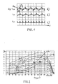
- a switching element in series with the motor (triac or thyristor) is delayed, ie switched on only by a certain phase or ignition angle ⁇ after the normal zero crossing of the input AC voltage U N.
- the synchronous frequency of the motor remains unchanged; a so-called slip speed control is implemented, but this is associated with increased power loss.
- the power output of the engine is reduced by converting part of the air gap power in the rotor into heat.
- the slip speed control does not change the idle speed, but the torque-torque-speed characteristic curve, with flatter characteristic curves being produced as the ignition angle increases.
- Fig. 2 associated engine characteristics are shown, which result from different ignition angles.
- the speed for example, changes significantly in the assumed operating point A 1 to A 2 by a transition from a first load characteristic curve L 1 to a second load characteristic curve L 2 , ie by approximately 170 rpm in the assumed example.
- the speed range is therefore heavily dependent on the load characteristic.
- such a control not only changes the amplitude of the motor current, but also generates harmonics.
- the third harmonic with 150 Hz forms the largest share.
- the harmonics cause additional losses and thus reduce the efficiency. They also increase the torque ripple and the noise level.
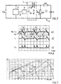
- FIG. 3 The operation of another known controller is illustrated in FIG. 3, in which case entire waves of the input AC voltage U N are blocked or let through. By cutting out half or full waves, the fundamental frequency of the motor changes; it is operated similarly to a frequency converter. For a given network frequency of 50 Hz, the example shown in FIG. 3 shows a frequency of 25 Hz with which the motor is operated. The resulting motor current I M is then no longer sinusoidal. As can clearly be seen from FIG. 3, the two half-waves of the current have a strong asymmetry. It has been recognized that the cause is that the river breaks down during the two blocked half-waves. The back emf is therefore significantly smaller during the first released half-wave than during the second, subsequent half-wave.
- a further control system is suitable for providing both known methods in combination.
- the fundamental frequency can be changed in that certain waves of the sinusoidal input AC voltage U N are blocked by the control unit 4 to form voltage gaps L and certain other waves are let through.
- a phase gating of the remaining successive positive and negative voltage half-waves with a certain phase gating angle ⁇ can also be carried out.
- the control unit 4 controls the switching device 2 as a function of zero crossings of the input AC voltage U N detected by means of a zero crossing detection device 6.
- the zero crossing detection device 6 is connected to the AC input voltage U N and is designed such that a control pulse is emitted to the control unit 4 via a signal line 8 at each zero crossing of the voltage. This control pulse is used to trigger the phase gating angle.
- a dynamic change in the ignition angle pattern is advantageously possible.
- a fundamental frequency for example reduced to 25 Hz (by blocking every second full wave)
- the remaining positive and negative half-waves are each cut differently. It is essential that the firing angle of the first half-wave is greater than the firing angle of the subsequent second half-wave.
- the half-waves of the input AC voltage U N are identified by the numbers 1 to 10.
- the first half-wave is driven with an ignition angle ⁇ 1 of, for example, 113 °, the second half-wave with a smaller ignition angle ⁇ 2 of, for example, 79 °.
- Two half-waves now follow, which are blocked by the fact that the switching device 2 is not activated.
- a 40 Hz basic frequency can be achieved with the following phase or ignition angle pattern: 0 °, 45 °, 90 °, 135 °, 180 °, 180 °, 180 °, 180 °, 45 °, 45 °.
- This ignition angle pattern is then repeated cyclically.
- the angle 180 ° means that the switching device 2 is not switched through by the control unit 4 over this phase angle.
- control system according to the invention can be seen in a significantly improved starting torque. That with the same power consumption compared to conventional Phase control systems assume almost double the values can. With a suitably chosen ignition angle pattern it is but also possible with the same starting torque to achieve reduced energy consumption.
- the third Harmonic with 150 Hz forms the largest part.
- the Control according to the invention are other current spectra generated. For example, with a control circuit that with operates at an operating frequency of 25 Hz, essentially 25 Hz, 50 Hz and 75 Hz components generated. In connection with the mechanics the different spectra generate different acoustic noises caused by suitable choice of special firing angle patterns can be minimized These additional options for noise optimization can do this with conventional phase control typical 100 Hz whistles can be avoided.
- this embodiment is the electronic switching device 2 preferably formed by a triac 10 in series with the Motor M is connected upstream, and its gate G via a Control line 12 from the control unit 4 - in particular a microcontroller or ASIC - is controlled.
- Fig. 5 is a common control of work winding AW and auxiliary winding HW over the common triac 10 provided.
- the switching device 2 contains two individual circuit breakers, preferably triacs 10a and 10b, the gates G 1 and G 2 of which are controlled separately by the control unit 4 via control lines 12a, 12b.
- An additional driver stage can also be provided between the control unit 4 and the circuit breaker. This control also takes place as a function of the zero crossings of the input AC voltage U N. While the current in the working and auxiliary winding is built up simultaneously in the first variant according to FIG. 5 and therefore there is no phase shift between the working and auxiliary winding shortly after the ignition, the two windings are now controlled separately in the circuit according to FIG. 8.
- a control angle pattern can be used which generates a basic frequency of 25 Hz and with the control angles ⁇ 1 and ⁇ 2 , 180 °, 180 ° for the auxiliary winding and with 180 °, ⁇ 3 , ⁇ 4 , 180 ° for the work winding works ( ⁇ 1 to ⁇ 4 variable).
- FIG. 9 A special control pattern is illustrated by way of example in FIG. 9.
- the AC input voltage U N is shown in FIG. 9a
- 9c and 9e show the associated currents I AW through the working winding and I HW through the auxiliary winding.
- FIGS. 9d and 9e show the associated currents I AW through the working winding and I HW through the auxiliary winding.
- the auxiliary winding is first switched on with an ignition angle ⁇ 1 , so that a current I HW can flow through the auxiliary winding.
- the work winding is not yet switched on at this time.
- the working winding is now energized with an ignition angle ⁇ 3 and the auxiliary winding with an ignition angle ⁇ 2 .
- the working winding is switched on again with an ignition angle ⁇ 4 , while the auxiliary winding is not ignited.
- FIG. 10 shows a speed-speed / torque characteristic curve A of a motor operated directly on the network without control in comparison to the corresponding characteristic curves B of a motor which is operated according to the invention by means of separate control of the working and auxiliary windings.
- a firing pattern is provided which adjusts, for example, a fundamental frequency of the motor of 16 2/3 Hz.
- an ignition pattern for the working winding AW with ignition angles of 0 °, 180 °, 180 ° and for the auxiliary winding HW of 180 °, 180 °, 97 ° has proven to be particularly favorable for efficiency and torque behavior.
- the first ignition angle of the working winding can be achieved by varying the first ignition angle of the working winding, the change in the ignition angle influencing the amplitude of the motor voltage. Due to the separate, but coordinated according to the invention, switching of the auxiliary and auxiliary windings, the starting torque of the motor also improves significantly in this embodiment and also achieves values which correspond to almost twice the value of the conventional phase control. It is also possible to change the direction of the speed without additional hardware, ie only by changing the ignition angle pattern. Ignition angles of 30 °, 180 °, 180 ° and the auxiliary winding of 180 °, 120 °, 180 ° have been found to be particularly favorable.
- the acoustic noise of the To influence the engine favorably. If found in practice is that a driven by the respective engine Device is excited to vibrate, so by Varying the firing angle pattern of the motor current even to that effect be changed that the disturbing vibrations at least reduced, if not eliminated.
- the optimal To determine the ignition angle empirically namely for optimization of efficiency and / or starting torque and / or vibration and / or Noise behavior and / or torque / speed characteristic.
- the results obtained in this way can be found in Storage means of the control unit 4 stored in a table become.
- the saved firing patterns will then change cyclically repeating the switching device 2 predetermined.
- the control unit 4 is controlled by a microcontroller or digital signal processor (DSP) with a sufficiently high level Computing power can optimize the engine can even be implemented in online mode.
- DSP digital signal processor
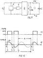
- this is the electronic switching device 2 formed by a PWM-modulated AC power controller, which is designed or controlled so that the Mode of operation of the embodiments according to FIGS. 5 and / or 8 in Basically "replicated” is also about efficiency and / or starting torque and / or torque / speed characteristic to optimize.
- the internal structure of such an AC power controller is known per se and therefore in Fig. 11 not shown in detail.
- AC power controller also called an AC chopper
- the amplitude of the motor voltage is infinitely variable change, as circuit breakers can be switched off here, e.g. bipolar transistors, MOS-FETs, IGBTs, etc. used be the current - unlike triacs and thyristors - can actively interrupt.
- This is typically done a timing of the circuit breaker with a Frequency from 18 to 20 kHz, i.e. with a frequency that is outside of human hearing.
- this AC power controller is controlled by the control unit 4 with a variable PWM ratio; that this - analogous to the explanations according to FIGS. 5 and 8 - a corresponding curve of the motor voltage U M can be generated. If, for example, entire half / full wave h of the input voltage are blocked, a PWM ratio of 0% is specified for the corresponding phase angle of 180 ° per half wave (see FIG. 12). A PWM ratio of 100% means that the input voltage is completely passed through the corresponding angle. Accordingly, a "phase gating" is practically possible by specifying up to a changeable phase or ignition angle ⁇ 0% PWM and then 100% PWM.
- control unit 4 supplies data from the the detection device 6 detected the zero crossings Control signals for the circuit breakers of the AC power controller.
- a fundamental frequency of 25 Hz is reached.
- other basic frequencies eg 16 2/3 Hz, 30 Hz, 40 Hz, etc.
- the invention is not limited to one Control with 0% or 100% PWM values or the simulation a triac circuit, but rather represents a general one Solution for the use of AC power controllers as Frequency converter.
- the basic frequency either the PWM signal or directly the switch-on and Circuit breaker opening times in the AC power controller controlled periodically repetitively. The This can be used for optimization of efficiency, starting torque, reduction of acoustic Noises and / or improvement of EMC behavior used become.
Description
- Fig. 1
- Zeit-Diagramme für den Spannungs-, Strom- und Leistungsverlauf einer bekannten Phasenanschnittsteuerung nach dem Stand der Technik,
- Fig. 2
- ein Motorkennlinien-Diagramm für eine solche bekannte Steuerung,
- Fig. 3
- Zeit-Diagramme analog zu Fig. 1 einer ebenfalls bekannten Steuerung, wobei ohne Phasenanschnitt jeweils ganze Wellen gesperrt werden,
- Fig. 4
- Zeit-Diagramme analog zu Fig. 1 bzw. 3 zu einem Steuersystem, nach dem Stand der Technik,
- Fig. 5
- ein Blockschaltbild des erfindungsgemäßen Steuersystems in einer ersten Schaltungsvariante,
- Fig. 6
- Zeit-Diagramme analog zu Fig. 4 zu einer bevorzugten Ausführungsform des erfindungsgemäßen Steuersystems,
- Fig. 7
- ein Motorkennlinien-Diagramm ähnlich Fig. 2, jedoch für die erfindungsgemäße Steuerung,
- Fig. 8
- ein Blockschaltbild einer zweiten Schaltungsvariante des erfindungsgemäßen Systems,
- Fig. 9
- Spannungs- und Stromkurven zu der zweiten Schaltungsvariante nach Fig. 8,
- Fig. 10
- gemessene Drehmomentkennlinienschar zur Schaltung nach Fig. 8 im Vergleich zur Drehmomentkennlinie eines direkt am Netz betriebenen Motors ohne Steuerung,
- Fig. 11
- ein Blockschaltbild einer dritten Schaltungsvariante als Alternative zu Fig. 5 und 8 und
- Fig. 12
- Diagramme zur Ausführung nach Fig. 11.
Claims (13)
- System zur Drehzahisteuerung von Wechselstrom-Asynchronmotoren, insbesondere Kondensatormotoren oder Spaltpolmotoren, wobei eine dem Motor (M) vorgeschaltete, steuerbare elektronische Schalteinrichtung (2) von einer Steuereinheit (4) so angesteuert wird, dass aus einer sinusförmigen Eingangswechselspannung (UN) eine zur Drehzahlveränderung variierbare Motorwechselspannung (UM) erzeugt wird, wobei die Steuereinheit (4) derart ausgebildet ist, dass die Motorwechselspannung (UM) bezüglich ihrer Grundfrequenz und/oder Amplitude durch Phasenanschnitt veränderbar ist, und wobei durch die Steuereinheit (4) bestimmte Halb- oder Vollwellen der sinusförmigen Eingangswechselspannung (UN) unter Bildung von Spannungslücken (L) vollständig gesperrt werden,
dadurch gekennzeichnet, dass die nicht gesperrten Halbwellen bei Phasenanschnitt unterschiedliche, sich periodisch wiederholende Zündwinkel aulweisen und
dass bei auf eine Spannungslücke (L) folgenden Halbwellen der Phasenanschnittwinkei (ϕ1) der ersten Halbwelle größer ist als der Phasenanschnittwinkel (ϕ2) der nachfolgenden zweiten Halbwelle bzw. Halbwellen, und zwar derart, dass ein aus der so erzeugten Motorwechselspannung (UM) resultierender Motorstrom (IM) im Wesentlichen symmetrisch zur Null-Linie verläuft. - System nach Anspruch 1,
dadurch gekennzeichnet, dass die Steuereinheit (4) die Schalteinrichtung (2) in Abhängigkeit von mittels einer Nulldurchgangserfassungseinrichtung (6) erfassten Nulldurchgängen der Eingangswechselspannung (UN) ansteuert - System nach Anspruch 1 oder 2 zur Steuerung eines Kondensatormotors, der eine Arbeitswicklung (AW) und parallel dazu eine in Reihe mit einem Kondensator (C) liegende Hilfswicklung (HW) aufweist,
dadurch gekennzeichnet, dass die Arbeitswicklung (AW) und die Hilfswicklung (HW) von der Steuereinheit (4) gemeinsam angesteuert werden. - System nach Anspruch 1 oder 2 zur Steuerung eines Kondensatormotors, der eine Arbeitswicklung (AW) und eine in Reihe mit einem Kondensator (C) liegende Hilfswicklung aufweist,
dadurch gekennzeichnet, dass die Arbeitswicklung (AW) und die Hilfwicklung (HW) von der Steuereinheit (4) durch separate Leistungsschalter angesteuert werden. - System nach einem der Ansprüche 1 bis 4,
dadurch gekennzeichnet, dass die elektronische Schalteinrichtung (2) als Leistungsschalter mindestens einen im Motor-Stromkreis liegenden Triac oder Thyristor (10; 10a, 10b) aufweist, dessen Gate (G; G1, G2) von der Steuereinheit (4) über eine Steuerleitung (12) mit einem variierbaren Zündwinkel-Muster angesteuert wird. - System nach einem der Ansprüche 1 bis 5,
dadurch gekennzeichnet, dass zwischen Steuereinheit (4) und Schalteinrichtung (2) eine Treiberschaltung zwischengeschaltet ist. - System nach einem der Ansprüche 1 bis 6,
dadurch gekennzeichnet, dass als Steuereiheit (4) eln Mikroprozessor oder ein Mikrocontroller oder ein digitaler Signalprozessor oder ein ASIC verwendet wird. - System nach einem der Ansprüche 1 bis 7,
dadurch gekennzeichnet, dass die Steuereinheit (4) Speichermittel zum tabellarischen Speichern von verschiedenen Zündwinkelmustern für verschiedene Arbeitspunkte aufweist. - System nach einem der Ansprüche 1 bis 8,
gekennzeichnet durch,
mindestens einen Drehzahl- und/oder Leistungs- und/oder Temperatur- und/oder Luftvolumen- und/oder Luftdruck- und/oder Luftgeschwindigkeits- und/oder Luftfeuchtigkeits- und/oder Schwingungssensor, wobei die Steuereinheit (4) durch Auswertung der Sensorsignale die Zündwinkelmuster im Betrieb anpasst. - System nach einem der Ansprüche 1 bis 9,
dadurch gekennzeichnet, dass durch geeignet gewählte Zündmuster die Motordrehrichtung veränderbar ist. - System nach einem der Ansprüche 1 bis 10,
dadurch gekennzeichnet, dass die elektronische Schalteinrichtung (2) durch einen PWM-modulierten Wechselstromsteller gebildet ist. - System nach Anspruch 11,
dadurch gekennzeichnet, dass die elektronische Steuereinheit (4) entweder das PWM-Verhältnis des Wechselstromstellers vorgibt, oder die Schaltzustände des Leistungsschalters direkt steuert. - System nach Anspruch 11 oder 12,
dadurch gekennzeichnet, dass die Steuereinheit (4) zwischen Steuerungsart mit veränderbarer Grundfrequenz und reiner Schlupfsteuerung variierbar ist.
Applications Claiming Priority (2)
| Application Number | Priority Date | Filing Date | Title |
|---|---|---|---|
| DE19843106A DE19843106B4 (de) | 1998-09-21 | 1998-09-21 | System zur Drehzahlsteuerung von Wechselstrom-Motoren |
| DE19843106 | 1998-09-21 |
Publications (3)
| Publication Number | Publication Date |
|---|---|
| EP0989666A1 EP0989666A1 (de) | 2000-03-29 |
| EP0989666B1 EP0989666B1 (de) | 2003-11-05 |
| EP0989666B9 true EP0989666B9 (de) | 2004-05-19 |
Family
ID=7881618
Family Applications (1)
| Application Number | Title | Priority Date | Filing Date |
|---|---|---|---|
| EP99117060A Expired - Lifetime EP0989666B9 (de) | 1998-09-21 | 1999-08-30 | System zur Drehzahlsteuerung von Wechselstrom-Motoren |
Country Status (6)
| Country | Link |
|---|---|
| US (1) | US6208113B1 (de) |
| EP (1) | EP0989666B9 (de) |
| CN (1) | CN1248405C (de) |
| AT (1) | ATE253783T1 (de) |
| DE (2) | DE19843106B4 (de) |
| ES (1) | ES2209300T3 (de) |
Families Citing this family (63)
| Publication number | Priority date | Publication date | Assignee | Title |
|---|---|---|---|---|
| IT1307378B1 (it) * | 1999-08-06 | 2001-11-06 | Askoll Holding Srl | Dispositivo elettronico di alimentazione di un motore sincrono conrotore a magneti permanenti a due coppie di poli. |
| DE10021918B4 (de) * | 2000-05-05 | 2005-10-13 | Ebm-Papst Mulfingen Gmbh & Co. Kg | System zum Ansteuern von Wechselstrom-Motoren |
| DE10032762B4 (de) * | 2000-07-05 | 2005-02-24 | Rational Ag | "Gargerät mit Spannungs-,Phasen-und /oder Frequenzumwandler" |
| DE10062940B4 (de) * | 2000-12-16 | 2012-09-20 | Ebm-Papst Mulfingen Gmbh & Co. Kg | Verfahren und Steuersystem zur elektronischen Drehzahlsteuerung eines Asynchronmotors |
| AU2002237761A1 (en) * | 2001-01-10 | 2002-07-24 | Iwatt Corporation | Phase-controlled ac-dc power converter |
| US6864659B2 (en) * | 2001-07-12 | 2005-03-08 | Varidigm Corporation | Variable speed controller for air moving applications using an AC induction motor |
| DE10156216A1 (de) * | 2001-11-15 | 2003-06-05 | Siemens Ag | Verfahren zur Minderung des Einflusses eines Gleichstromanteils im Laststrom eines Asynchronmotors |
| DE10220779A1 (de) * | 2002-05-10 | 2003-11-27 | Bosch Gmbh Robert | Verfahren und Vorrichtung zum Ansteuern eines elektrischen Motors |
| DE10231773B4 (de) * | 2002-07-13 | 2005-02-24 | Danfoss Drives A/S | Umrichter zum drehzahlvariablen Betreiben eines Kondensatormotors und Verfahren zum Steuern eines Kondensatormotors |
| US6713986B1 (en) * | 2002-11-26 | 2004-03-30 | Energy Savers International | Controller for air conditioners and heat pumps |
| US20040251344A1 (en) * | 2003-02-07 | 2004-12-16 | Varidigm Corporation | Pressure sensing system |
| JP2005052420A (ja) * | 2003-08-05 | 2005-03-03 | Aruze Corp | モータ停止制御装置 |
| US7279857B2 (en) * | 2003-08-27 | 2007-10-09 | Hewlett-Packard Development Company, L.P. | System, method, and computer-readable medium for reduction of commutation-related acoustic noise in a fan system |
| KR20050108640A (ko) * | 2004-05-12 | 2005-11-17 | 엘지전자 주식회사 | 콘덴서 운전형 단상 유도 전동기 |
| KR100631533B1 (ko) * | 2004-09-13 | 2006-10-09 | 엘지전자 주식회사 | 비엘디시 모터의 회전자 구조 |
| WO2006033085A2 (en) * | 2004-09-24 | 2006-03-30 | Arcelik Anonim Sirketi | A motor control circuit |
| KR20060055046A (ko) * | 2004-11-17 | 2006-05-23 | 삼성전자주식회사 | 단상유도전동기 및 그 소음 저감 방법 |
| KR100690652B1 (ko) * | 2004-11-23 | 2007-03-09 | 엘지전자 주식회사 | 공기조화기의 팬모터 속도가변장치 |
| FR2879047B1 (fr) * | 2004-12-07 | 2007-09-14 | Somfy Sas | Procede d'alimentation d'un moteur de manoeuvre d'un volet roulant et dispositif de volet roulant motorise |
| DE102005004061A1 (de) * | 2005-01-21 | 2006-07-27 | E.G.O. Elektro-Gerätebau GmbH | Vorrichtung zur Steuerung eines Kondensatormotors und Lüftungsvorrichtung mit einer solchen Vorrichtung |
| SI21983A (sl) * | 2005-02-21 | 2006-08-31 | DOMEL, Elketromotorji in gospodinjski aparati, d.d. | Vezje in postopek za krmiljenje reluktancnega motorja |
| PL1708354T3 (pl) * | 2005-03-31 | 2010-05-31 | Grundfos Management As | Silnik głębinowy |
| EP1734648B1 (de) * | 2005-06-13 | 2012-08-15 | Brose Fahrzeugteile GmbH & Co. KG, Würzburg | Asymmetrische Ansteuerung eines sensorlosen und bürstenlosen Elektromotors |
| US7203077B2 (en) * | 2005-07-20 | 2007-04-10 | General Atomics Electronic Systems, Inc. | Resonant charge power supply topology for high pulse rate pulsed power systems |
| EP2122304B1 (de) | 2007-03-09 | 2012-11-14 | Koninklijke Philips Electronics N.V. | Steuerung einer leistung eines elektromotors |
| ES1065745Y (es) * | 2007-06-21 | 2008-01-16 | Coprecitec Sl | Dispositivo de control de una lavadora |
| SE0701697L (sv) | 2007-07-11 | 2009-01-12 | Flaekt Woods Ab | Styrningsprincip av en enfasmotor, t ex en motor i ett fläktsystem |
| EP2020746A1 (de) * | 2007-08-02 | 2009-02-04 | Grundfos Management A/S | Verfahren zum Ansteuern eines Asynchronmotors |
| US7847510B2 (en) * | 2008-02-29 | 2010-12-07 | Johnson Controls Technology Company | Controlling switching of thyristors to reduce power loss in variable speed motor |
| US7986540B2 (en) * | 2008-03-07 | 2011-07-26 | Johnson Controls Technology Company | Controlling switching noise of an inductively loaded thyristor |
| JP4678699B2 (ja) * | 2009-09-29 | 2011-04-27 | シャープ株式会社 | モータ制御装置 |
| EP2517349B1 (de) * | 2009-12-23 | 2014-03-26 | Robert Bosch GmbH | Bremseinrichtung für einen universalmotor |
| EP2545640A1 (de) | 2010-01-12 | 2013-01-16 | MK Regeltechnik AG | Verfahren und vorrichtung zum betreiben eines asynchronmotors mit gesteigerter effizienz |
| GB201006384D0 (en) * | 2010-04-16 | 2010-06-02 | Dyson Technology Ltd | Control of a brushless motor |
| GB201006398D0 (en) | 2010-04-16 | 2010-06-02 | Dyson Technology Ltd | Control of a brushless motor |
| GB201006388D0 (en) | 2010-04-16 | 2010-06-02 | Dyson Technology Ltd | Control of brushless motor |
| GB201006387D0 (en) | 2010-04-16 | 2010-06-02 | Dyson Technology Ltd | Control of a brushless motor |
| GB201006395D0 (en) | 2010-04-16 | 2010-06-02 | Dyson Technology Ltd | Control of a brushless motor |
| GB201006397D0 (en) | 2010-04-16 | 2010-06-02 | Dyson Technology Ltd | Control of a brushless motor |
| GB201006390D0 (en) | 2010-04-16 | 2010-06-02 | Dyson Technology Ltd | Control of a brushless motor |
| GB201006392D0 (en) | 2010-04-16 | 2010-06-02 | Dyson Technology Ltd | Controller for a brushless motor |
| GB201006386D0 (en) | 2010-04-16 | 2010-06-02 | Dyson Technology Ltd | Control of a brushless motor |
| GB201006391D0 (en) | 2010-04-16 | 2010-06-02 | Dyson Technology Ltd | Control of a brushless permanent-magnet motor |
| GB201006396D0 (en) * | 2010-04-16 | 2010-06-02 | Dyson Technology Ltd | Control of a brushless motor |
| PL2410653T3 (pl) * | 2010-07-23 | 2019-09-30 | Askoll Holding S.R.L. | Urządzenie do sterowania synchronicznym silnikiem elektrycznym z wirnikiem z magnesami trwałymi |
| GB2484289B (en) | 2010-10-04 | 2013-11-20 | Dyson Technology Ltd | Control of an electrical machine |
| BRPI1101069A2 (pt) * | 2011-03-01 | 2013-06-04 | Whirlpool Sa | mÉtodo de partida para um motor de induÇço monofÁsico, dispositivo de partida para motor monofÁsico e sistema de partida para o mesmo |
| US8587266B2 (en) * | 2011-04-06 | 2013-11-19 | Tai-Her Yang | Synchronous regulation circuit for turn-on and turn-off phase angle of the AC voltage |
| JP2014521296A (ja) * | 2011-07-13 | 2014-08-25 | ジングルス・テヒノロギース・アクチェンゲゼルシャフト | 立ち上がりエッジもしくは立ち下がりエッジの位相カッティングを用いて交流ネットワークにおけるいくつかの負荷を動作させるための方法 |
| US8937449B2 (en) * | 2012-08-13 | 2015-01-20 | Larry G. Seever | Apparatus and method for efficiently powering a one-phase motor |
| US8947030B2 (en) | 2012-12-28 | 2015-02-03 | Eaton Corporation | Low switch count AC-to-AC power converter |
| RU2532528C1 (ru) * | 2013-05-31 | 2014-11-10 | Открытое акционерное общество "Красногорский завод им. С.А. Зверева" | Устройство управления электромагнитным моментом двухфазного двигателя переменного тока |
| US9559628B2 (en) | 2013-10-25 | 2017-01-31 | Black & Decker Inc. | Handheld power tool with compact AC switch |
| JP6203134B2 (ja) * | 2014-06-20 | 2017-09-27 | オリンパス株式会社 | 医療用マニピュレータの制御方法 |
| EP2985083A1 (de) * | 2014-08-15 | 2016-02-17 | Nilfisk-Advance A/S | Hochdruckreiniger mit einstellbarem Druck- oder Flusswert |
| DE102014018664A1 (de) * | 2014-12-13 | 2016-06-16 | Baumüller Nürnberg GmbH | Verfahren zum Betrieb eines Umrichters sowie Umrichter |
| CN105042711A (zh) * | 2015-07-29 | 2015-11-11 | 深圳奥郎格环保有限公司 | 空气净化器 |
| CN106452281A (zh) * | 2016-10-17 | 2017-02-22 | 南天日 | 一种交流电机的调速方法及调速系统 |
| RU185924U1 (ru) * | 2018-09-04 | 2018-12-25 | федеральное государственное бюджетное образовательное учреждение высшего образования "Алтайский государственный технический университет им. И.И. Ползунова" (АлтГТУ) | Устройство управления однофазным двухобмоточным асинхронным электродвигателем |
| RU185627U1 (ru) * | 2018-09-04 | 2018-12-13 | федеральное государственное бюджетное образовательное учреждение высшего образования "Алтайский государственный технический университет им. И.И. Ползунова" (АлтГТУ) | Полупроводниковое устройство управления однофазным двухобмоточным асинхронным электродвигателем |
| US11611302B2 (en) * | 2020-09-26 | 2023-03-21 | Emerson Electric Co. | Systems and methods for controlling inducer motor speed |
| RU2767754C1 (ru) * | 2021-05-28 | 2022-03-21 | федеральное государственное бюджетное образовательное учреждение высшего образования "Алтайский государственный технический университет им. И.И. Ползунова" (АлтГТУ) | Реверсивное устройство регулирования скорости однофазного асинхронного электродвигателя |
| EP4106184A1 (de) * | 2021-06-15 | 2022-12-21 | Electrolux Appliances Aktiebolag | Küchengerät mit einer absaugvorrichtung |
Family Cites Families (18)
| Publication number | Priority date | Publication date | Assignee | Title |
|---|---|---|---|---|
| DD94666A (de) * | ||||
| DE2110796C3 (de) * | 1971-03-06 | 1980-01-10 | Siemens Ag, 1000 Berlin Und 8000 Muenchen | Schaltungsanordnung zur untersynchronen Drehzahlsteuerung Zweiphasen-Asynchronmotors |
| BE787900A (fr) * | 1971-08-25 | 1973-02-23 | Borg Warner | Dispositifs de controle pour controler la vitesse d'un moteur acourant alternatif |
| DE2246463A1 (de) * | 1972-09-22 | 1974-04-04 | Kraftwerk Union Ag | Koordinatenanzeigegeraet zur anzeige von messwertpaaren |
| US3908158A (en) * | 1973-05-09 | 1975-09-23 | Borg Warner | Control system for adjusting a-c motor speed at line frequency or a subharmonic of the line frequency |
| DE2702142C3 (de) * | 1977-01-20 | 1979-08-02 | Robert Bosch Gmbh, 7000 Stuttgart | Anordnung zur Steuerung der Drehzahl eines Universalmotors |
| DE2842391A1 (de) * | 1978-09-29 | 1980-04-17 | Bosch Gmbh Robert | Vorrichtung zum umschalten der drehzahl eines drehstrommotors |
| US4266175A (en) * | 1979-09-24 | 1981-05-05 | Eaton Corp. | Secondary thyristor control for AC wound rotor motors |
| DD216586A1 (de) * | 1983-07-04 | 1984-12-12 | Akad Wissenschaften Ddr | Drehfrequenz-verstellung fuer sterngeschaltete dreiphasen-drehfeld-motoren oder -motorgruppen |
| DE3427479A1 (de) * | 1984-07-25 | 1986-02-06 | Siemens AG, 1000 Berlin und 8000 München | Verfahren zur anschnitt-steuerung der spannungshalbschwingungen eines drehstrom-stellers mit zwei antiparallel steuerbaren strompfaden je phase fuer einen kaefiglaeufermotor |
| JPH0763221B2 (ja) * | 1984-08-16 | 1995-07-05 | 株式会社明電舍 | 電力変換器のゲ−トパルス発生方式 |
| DE3830196A1 (de) * | 1988-09-06 | 1990-03-15 | Loewe Pumpenfabrik Gmbh | Verfahren zur nutzung von phasenanschnittsteuerungen als frequenzumrichter |
| US4996470A (en) * | 1989-07-14 | 1991-02-26 | Allen-Bradley Company, Inc. | Electric motor speed control apparatus and method |
| DE4130532C2 (de) * | 1991-09-13 | 1995-07-13 | Fraunhofer Ges Forschung | Verfahren und Vorrichtung zur Regulierung von einem an ein Wechselstromnetz angeschlossenen Wechselstrommotor |
| IT1254734B (it) * | 1992-03-24 | 1995-10-10 | Faac Spa | Metodo e dispositivo per il controllo della velocita' di motori asincroni |
| DE4222431A1 (de) * | 1992-07-09 | 1994-01-13 | Wilo Gmbh | Vorrichtung zur Wicklungsumschaltung eines Einphasen-Elektromotors |
| DE4307096C2 (de) * | 1993-03-06 | 1995-08-03 | Grundfos As | Verfahren zum Ansteuern eines wechselstromgespeisten Einphaseninduktionsmotors |
| AU7616096A (en) * | 1995-11-30 | 1997-06-19 | William Harry Kemp | Current modulation motor controller |
-
1998
- 1998-09-21 DE DE19843106A patent/DE19843106B4/de not_active Expired - Fee Related
-
1999
- 1999-08-30 ES ES99117060T patent/ES2209300T3/es not_active Expired - Lifetime
- 1999-08-30 AT AT99117060T patent/ATE253783T1/de not_active IP Right Cessation
- 1999-08-30 EP EP99117060A patent/EP0989666B9/de not_active Expired - Lifetime
- 1999-08-30 DE DE59907612T patent/DE59907612D1/de not_active Expired - Lifetime
- 1999-09-21 US US09/399,664 patent/US6208113B1/en not_active Expired - Fee Related
- 1999-09-21 CN CNB991207165A patent/CN1248405C/zh not_active Expired - Fee Related
Also Published As
| Publication number | Publication date |
|---|---|
| CN1248405C (zh) | 2006-03-29 |
| EP0989666B1 (de) | 2003-11-05 |
| DE19843106B4 (de) | 2005-08-18 |
| CN1248817A (zh) | 2000-03-29 |
| DE19843106A1 (de) | 2000-03-30 |
| ES2209300T3 (es) | 2004-06-16 |
| ATE253783T1 (de) | 2003-11-15 |
| US6208113B1 (en) | 2001-03-27 |
| DE59907612D1 (de) | 2003-12-11 |
| EP0989666A1 (de) | 2000-03-29 |
Similar Documents
| Publication | Publication Date | Title |
|---|---|---|
| EP0989666B9 (de) | System zur Drehzahlsteuerung von Wechselstrom-Motoren | |
| DE19843106A9 (de) | System zur Drehzahlsteuerung von Wechselstrom-Motoren | |
| EP0831580B1 (de) | Einrichtung zur Antriebsstromsteuerung eines elektrisch kommutierten Permanentmagnet-Motors | |
| EP2178201B1 (de) | Verfahren und Steuersystem zum Umformen einer Speisewechselspannung in eine Verbraucher-Betriebsspannung mit einstellbarem Effektivwert | |
| DE60120664T2 (de) | Pwm-frequenzwandler | |
| WO2009015826A1 (de) | Verfahren zum ansteuern eines asynchronmotors | |
| DE102005045401A1 (de) | Verfahren zur Stromversorgung eines über eine Halbleiter-Leistungsendstufe elektronisch kommutierbaren Gleichstrommotors | |
| DE4442151A1 (de) | Schaltungsanordnung zum Steuern eines elektronisch kommutierten Motors | |
| DE102011081215A1 (de) | Drehstrommaschinen-Ansteuerungsverfahren und -vorrichtung | |
| WO2009118135A1 (de) | Verfahren zum ansteuern eines mehrphasigen in sternschaltung betriebenen elektromotors | |
| EP3285381A1 (de) | Verfahren zum betreiben einer elektrischen maschine und elektrische maschine | |
| DE4413802C2 (de) | Verfahren und Vorrichtung zum Steuern der Drehzahl eines elektrischen Dreiphasen-Asynchronmotors | |
| WO2003005555A1 (de) | Drehzahlsteuerung für einen universalmotor mit reduzierter stromschwankung | |
| DE19535676C2 (de) | Verfahren zur Leistungssteuerung eines Induktionsmotors | |
| CH660652A5 (de) | Wechselrichter-anordnung. | |
| EP1396076A1 (de) | Verfahren zur steuerung eines elektronish kommutierten gleichstrommotors | |
| DE10062940B4 (de) | Verfahren und Steuersystem zur elektronischen Drehzahlsteuerung eines Asynchronmotors | |
| WO2002003538A1 (de) | Verfahren zum betrieb eines bürstenlosen gleichstrommotors | |
| DE19705907C2 (de) | Verfahren und Vorrichtung zur Leistungssteuerung von an ein Wechselspannungs-Versorgungsnetz angeschlossenen elektrischen Verbrauchern | |
| EP1533892B1 (de) | Verfahren zum Reduzieren der Auslaufzeit eines Elektromotors | |
| DE3042927C2 (de) | Anordnung zur Verbesserung des Wirkungsgrades eines Dreiphasendrehstromasynchronmotors | |
| DE3607162A1 (de) | Wechselstrommotor fuer insbesondere umwaelzpumpen | |
| DE1638415C3 (de) | Elektrischer Drehstrommotor, insbesondere Asynchronmotor, zum Antrieb einer überwiegend in einem bestimmten Teildrehzahlbereich betriebenen Arbeitsmaschine | |
| DE10024651B4 (de) | Verfahren und Schaltungsanordnung zum Starten von elektrischen Motoren | |
| DE3933520C2 (de) | Verfahren zum Betrieb zweier parallelgeschalteter, gemeinsam eine Maschine speisender Umrichter als Direktumrichter bei niedrigen Maschinenfrequenzen und als I-Umrichter bei höheren Maschinenfrequenzen |
Legal Events
| Date | Code | Title | Description |
|---|---|---|---|
| PUAI | Public reference made under article 153(3) epc to a published international application that has entered the european phase |
Free format text: ORIGINAL CODE: 0009012 |
|
| AK | Designated contracting states |
Kind code of ref document: A1 Designated state(s): AT BE CH CY DE DK ES FI FR GB GR IE IT LI LU MC NL PT SE |
|
| AX | Request for extension of the european patent |
Free format text: AL;LT;LV;MK;RO;SI |
|
| 17P | Request for examination filed |
Effective date: 20000608 |
|
| AKX | Designation fees paid |
Free format text: AT BE CH CY DE DK ES FI FR GB GR IE IT LI LU MC NL PT SE |
|
| 17Q | First examination report despatched |
Effective date: 20020304 |
|
| GRAH | Despatch of communication of intention to grant a patent |
Free format text: ORIGINAL CODE: EPIDOS IGRA |
|
| GRAH | Despatch of communication of intention to grant a patent |
Free format text: ORIGINAL CODE: EPIDOS IGRA |
|
| RAP1 | Party data changed (applicant data changed or rights of an application transferred) |
Owner name: EBM WERKE GMBH & CO. KG |
|
| GRAA | (expected) grant |
Free format text: ORIGINAL CODE: 0009210 |
|
| AK | Designated contracting states |
Kind code of ref document: B1 Designated state(s): AT BE CH CY DE DK ES FI FR GB GR IE IT LI LU MC NL PT SE |
|
| PG25 | Lapsed in a contracting state [announced via postgrant information from national office to epo] |
Ref country code: NL Free format text: LAPSE BECAUSE OF FAILURE TO SUBMIT A TRANSLATION OF THE DESCRIPTION OR TO PAY THE FEE WITHIN THE PRESCRIBED TIME-LIMIT Effective date: 20031105 Ref country code: IE Free format text: LAPSE BECAUSE OF FAILURE TO SUBMIT A TRANSLATION OF THE DESCRIPTION OR TO PAY THE FEE WITHIN THE PRESCRIBED TIME-LIMIT Effective date: 20031105 Ref country code: FI Free format text: LAPSE BECAUSE OF FAILURE TO SUBMIT A TRANSLATION OF THE DESCRIPTION OR TO PAY THE FEE WITHIN THE PRESCRIBED TIME-LIMIT Effective date: 20031105 Ref country code: CY Free format text: LAPSE BECAUSE OF FAILURE TO SUBMIT A TRANSLATION OF THE DESCRIPTION OR TO PAY THE FEE WITHIN THE PRESCRIBED TIME-LIMIT Effective date: 20031105 |
|
| REG | Reference to a national code |
Ref country code: GB Ref legal event code: FG4D Free format text: NOT ENGLISH |
|
| REG | Reference to a national code |
Ref country code: CH Ref legal event code: EP |
|
| REG | Reference to a national code |
Ref country code: CH Ref legal event code: NV Representative=s name: BOVARD AG PATENTANWAELTE |
|
| REF | Corresponds to: |
Ref document number: 59907612 Country of ref document: DE Date of ref document: 20031211 Kind code of ref document: P |
|
| GBT | Gb: translation of ep patent filed (gb section 77(6)(a)/1977) |
Effective date: 20031209 |
|
| REG | Reference to a national code |
Ref country code: IE Ref legal event code: FG4D Free format text: GERMAN |
|
| PG25 | Lapsed in a contracting state [announced via postgrant information from national office to epo] |
Ref country code: SE Free format text: LAPSE BECAUSE OF FAILURE TO SUBMIT A TRANSLATION OF THE DESCRIPTION OR TO PAY THE FEE WITHIN THE PRESCRIBED TIME-LIMIT Effective date: 20040205 Ref country code: GR Free format text: LAPSE BECAUSE OF FAILURE TO SUBMIT A TRANSLATION OF THE DESCRIPTION OR TO PAY THE FEE WITHIN THE PRESCRIBED TIME-LIMIT Effective date: 20040205 Ref country code: DK Free format text: LAPSE BECAUSE OF FAILURE TO SUBMIT A TRANSLATION OF THE DESCRIPTION OR TO PAY THE FEE WITHIN THE PRESCRIBED TIME-LIMIT Effective date: 20040205 |
|
| NLV1 | Nl: lapsed or annulled due to failure to fulfill the requirements of art. 29p and 29m of the patents act | ||
| ET | Fr: translation filed | ||
| REG | Reference to a national code |
Ref country code: ES Ref legal event code: FG2A Ref document number: 2209300 Country of ref document: ES Kind code of ref document: T3 |
|
| REG | Reference to a national code |
Ref country code: IE Ref legal event code: FD4D |
|
| PG25 | Lapsed in a contracting state [announced via postgrant information from national office to epo] |
Ref country code: LU Free format text: LAPSE BECAUSE OF NON-PAYMENT OF DUE FEES Effective date: 20040830 Ref country code: AT Free format text: LAPSE BECAUSE OF NON-PAYMENT OF DUE FEES Effective date: 20040830 |
|
| PG25 | Lapsed in a contracting state [announced via postgrant information from national office to epo] |
Ref country code: MC Free format text: LAPSE BECAUSE OF NON-PAYMENT OF DUE FEES Effective date: 20040831 Ref country code: BE Free format text: LAPSE BECAUSE OF NON-PAYMENT OF DUE FEES Effective date: 20040831 |
|
| PLBE | No opposition filed within time limit |
Free format text: ORIGINAL CODE: 0009261 |
|
| STAA | Information on the status of an ep patent application or granted ep patent |
Free format text: STATUS: NO OPPOSITION FILED WITHIN TIME LIMIT |
|
| 26N | No opposition filed |
Effective date: 20040806 |
|
| BERE | Be: lapsed |
Owner name: *EBM WERKE G.M.B.H. & CO. K.G. Effective date: 20040831 |
|
| BERE | Be: lapsed |
Owner name: *EBM WERKE G.M.B.H. & CO. K.G. Effective date: 20040831 |
|
| REG | Reference to a national code |
Ref country code: CH Ref legal event code: NV Representative=s name: BRAUNPAT BRAUN EDER AG |
|
| PG25 | Lapsed in a contracting state [announced via postgrant information from national office to epo] |
Ref country code: PT Free format text: LAPSE BECAUSE OF NON-PAYMENT OF DUE FEES Effective date: 20040405 |
|
| PGFP | Annual fee paid to national office [announced via postgrant information from national office to epo] |
Ref country code: FR Payment date: 20090826 Year of fee payment: 11 Ref country code: ES Payment date: 20090807 Year of fee payment: 11 |
|
| PGFP | Annual fee paid to national office [announced via postgrant information from national office to epo] |
Ref country code: GB Payment date: 20090826 Year of fee payment: 11 Ref country code: CH Payment date: 20090831 Year of fee payment: 11 |
|
| PGFP | Annual fee paid to national office [announced via postgrant information from national office to epo] |
Ref country code: DE Payment date: 20091028 Year of fee payment: 11 |
|
| PGFP | Annual fee paid to national office [announced via postgrant information from national office to epo] |
Ref country code: IT Payment date: 20090727 Year of fee payment: 11 |
|
| REG | Reference to a national code |
Ref country code: CH Ref legal event code: PL |
|
| GBPC | Gb: european patent ceased through non-payment of renewal fee |
Effective date: 20100830 |
|
| PG25 | Lapsed in a contracting state [announced via postgrant information from national office to epo] |
Ref country code: LI Free format text: LAPSE BECAUSE OF NON-PAYMENT OF DUE FEES Effective date: 20100831 Ref country code: CH Free format text: LAPSE BECAUSE OF NON-PAYMENT OF DUE FEES Effective date: 20100831 |
|
| REG | Reference to a national code |
Ref country code: FR Ref legal event code: ST Effective date: 20110502 |
|
| PG25 | Lapsed in a contracting state [announced via postgrant information from national office to epo] |
Ref country code: IT Free format text: LAPSE BECAUSE OF NON-PAYMENT OF DUE FEES Effective date: 20100830 |
|
| REG | Reference to a national code |
Ref country code: DE Ref legal event code: R119 Ref document number: 59907612 Country of ref document: DE Effective date: 20110301 |
|
| PG25 | Lapsed in a contracting state [announced via postgrant information from national office to epo] |
Ref country code: FR Free format text: LAPSE BECAUSE OF NON-PAYMENT OF DUE FEES Effective date: 20100831 Ref country code: DE Free format text: LAPSE BECAUSE OF NON-PAYMENT OF DUE FEES Effective date: 20110301 |
|
| PG25 | Lapsed in a contracting state [announced via postgrant information from national office to epo] |
Ref country code: GB Free format text: LAPSE BECAUSE OF NON-PAYMENT OF DUE FEES Effective date: 20100830 |
|
| REG | Reference to a national code |
Ref country code: ES Ref legal event code: FD2A Effective date: 20111019 |
|
| PG25 | Lapsed in a contracting state [announced via postgrant information from national office to epo] |
Ref country code: ES Free format text: LAPSE BECAUSE OF NON-PAYMENT OF DUE FEES Effective date: 20100831 |