EP0989256A1 - Arbeitsverfahren und Reinigungsgerät zum Reinigen eines Schwimmbeckens - Google Patents
Arbeitsverfahren und Reinigungsgerät zum Reinigen eines Schwimmbeckens Download PDFInfo
- Publication number
- EP0989256A1 EP0989256A1 EP99117503A EP99117503A EP0989256A1 EP 0989256 A1 EP0989256 A1 EP 0989256A1 EP 99117503 A EP99117503 A EP 99117503A EP 99117503 A EP99117503 A EP 99117503A EP 0989256 A1 EP0989256 A1 EP 0989256A1
- Authority
- EP
- European Patent Office
- Prior art keywords
- cleaning device
- motors
- control device
- speed
- working method
- Prior art date
- Legal status (The legal status is an assumption and is not a legal conclusion. Google has not performed a legal analysis and makes no representation as to the accuracy of the status listed.)
- Granted
Links
Images

Classifications
-
- E—FIXED CONSTRUCTIONS
- E04—BUILDING
- E04H—BUILDINGS OR LIKE STRUCTURES FOR PARTICULAR PURPOSES; SWIMMING OR SPLASH BATHS OR POOLS; MASTS; FENCING; TENTS OR CANOPIES, IN GENERAL
- E04H4/00—Swimming or splash baths or pools
- E04H4/14—Parts, details or accessories not otherwise provided for
- E04H4/16—Parts, details or accessories not otherwise provided for specially adapted for cleaning
- E04H4/1654—Self-propelled cleaners
Definitions
- the invention relates to a working method for a cleaning device for cleaning a swimming pool according to the Preamble of claim 1 and a cleaning device for cleaning a swimming pool according to the preamble of Claim 8.
- DE-3 110 203 describes a method and an apparatus for Cleaning a swimming pool in a known manner moves the bottom of a water-filled swimming pool back and forth and cleans it by suction.
- the device has two motors so that both sides of the chassis are independent Walk forward or backward from each other or stand still can.
- the device also has a control device, the four arranged at the corners of the device Sensor is affected and the movement of the device on the Pool floor between opposite pool walls controls in a zigzag course.
- the device moves alternately forward and backward. It turns on the pool walls not, but performs small swiveling movements there out. On the one hand, these pivoting movements are used for alignment the cleaning device on the pool wall and on the other the subsequent setting of a new direction of movement.
- the cleaning device for both sides of the Chassis has one motor each, is used to achieve the Alignment movements and changes in direction are each one of the both engines switched off, the other during the Alignment process or continues during a delay time. This turns the cleaning device around the disused drive part.
- the object of the present invention is a simple procedure for cleaning and an inexpensive Specify cleaning device, both for pools different Size as well as different for pools Form can be used and reliable cleaning of the Ensure pelvic floor.
- the stated object is achieved by the features solved in the characterizing part of claims 1 and 8.
- This is essentially achieved by for one left and a right-hand chassis part means for measurement the distance covered on the pelvic floor and middle for differential control of the motors of the two chassis parts used at different speeds become.
- This initially achieves that the control device of the cleaning device automatically and automatically the one required for the next cleaning cycle Calculate the change in direction and the necessary control functions can perform.
- the respective direction change angle is very exactly and without the help of costly control technology such as driving direction sensors can be.
- control device of the cleaning device is constructed in such a way that between two or more different work programs can be chosen.
- a first work program for cleaning swimming pools Any shape can be provided, the cleaning device no alignment procedures for this work program the pool walls.
- Another work program can be used, for example, for cleaning swimming pools with at least one suitable straight line Reference swimming pool wall can be provided, the cleaning device in this work program on the reference swimming pool wall an alignment with it makes.
- the chassis each has a motor for a left and one right-hand chassis part.
- a control device controls the interaction of the motors of the two chassis parts.
- the Control device includes separate speed control devices for speed control of the two motors.
- the control device is also for a differential Speed control of the two motors designed. This means that the two engines are different Target speeds can be operated. For driving straight ahead (forwards or backwards) the two speed control devices the same size Target speeds specified.
- the cleaning device has at the corners on the front and rear arranged contact means for generating control signals in the event of the cleaning device colliding with a Pool wall or an obstacle.
- the contact means can use the contact means as a mechanical switching sensor relatively long spring travel (to ensure the effective Accumulation on the pool wall or the obstacle to avoid).
- the cleaning device also has means on both chassis parts to measure the distance traveled during the back and forth movement Distances. These are preferably arranged on both sides Pulse generator on the drive wheels (or on the Driving belts acting drive wheels). Due to the design known relationship between the number of Revolutions (or impulses) per drive wheel and the resulting one resulting distance can be the total distance covered Distance can be determined.
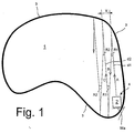
- Fig. 1 shows a swimming pool 1 of irregular shape with a schematic course of the cleaning path according to a first work program.
- This work program includes no alignment of the cleaning device 2 to the Pool walls 3.
- the cleaning device 2 is started at a suitable location on the swimming pool wall 3 at a starting position 4 in the desired starting direction A.
- the cleaning device first moves in this direction in a straight line to the counter wall.
- the distance covered by the cleaning device during this movement is continuously measured.
- the contact means arranged on the front of the cleaning device generate a control signal, which causes the undercarriage to be switched off before the cleaning device effectively hits the swimming pool wall.
- the control device is provided with the measured distance d 1 last.
- both motors with during the change of direction operated constant, but different target speeds. Because the distance traveled on both parts of the chassis can now be measured due to the different arc lengths for a certain direction change angle to be achieved the duration of the second operating phase for one certain target speed combinations of the two motors be determined.
- the duration of the Change of direction of one of the motors to a target speed brought, which is higher than that at the end of the Direction change process to be reached and for the crossing target speed to be maintained on the pool floor. In this way it is achieved that the direction changes take place smoothly and smoothly, so that a high driving stability results. Since every chassis part with equipped with an independent speed control loop high accuracy results.
- both Motors brought to the same target speed, whereby the last speed reached to cross the swimming pool floor is maintained.
- the cleaning device now drives in a straight direction B backwards onto the start wall to.
- a control signal which causes the undercarriage to turn off again is before the cleaning device effectively on the pool wall 3 accumulates.
- the distance d 2 is measured.
- the distance d 2 is greater than the distance d 1 measured first.
- the newly calculated direction change angle R 2 is smaller than the direction change angle R 1 the next time it contacts the counter wall. This ensures that the cleaning paths of the cleaning device are always overlapping.
- Fig. 2 shows a swimming pool of rectangular shape with schematic course of the cleaning path according to a second work program.
- This work program includes Alignment of the cleaning device with respect to a reference swimming pool wall.
- This work program can be used for swimming pool shapes, where a suitable straight reference swimming pool wall 3 'is available.
- the rectangular shape shown in FIG. 2 is therefore only to be understood as an example.
- the cleaning device 2 is also used in this work program at a suitable location on the pool wall 3 at a Starting position 4 positioned. It will, however, initially reversed to automatically and parallel to the Align reference swimming pool wall 3 '. After that it gets in the start direction A started.
- the minimum distance m is approximately in the range of 0.2 m. This is to ensure that no annoying lateral contact even at maximum distance d occurs between the cleaning device and the pool wall (to take alignment errors into account).
- the two motors of the chassis parts are preferably electrical Travel drives, the motors via reduction gears and drive wheels each non-positively on both sides arranged drive treadmills act. Because of The drive blocks are symmetrical for optimum weight distribution arranged at the front and back.
- the controllability is preferably DC motors with revolution counters used. Set electronic engine governors the pulses evaluated by the control device and Command signals into electrical manipulated variables.
- the setpoint speed specified by the control device or The target driving speed is the respective motor controller fed.
- the actual speed or actual driving speed via the revolution counter recorded separately and also the respective engine controllers fed.
- each travel drive has one own speed control loop in which the target and Actual values are compared and precisely adjusted.
- the drive treadmills will spin at the start of the travel drive prevented by the two Motors via one defined by the control device Run-up ramp gently run up together.
Landscapes
- Engineering & Computer Science (AREA)
- Architecture (AREA)
- Civil Engineering (AREA)
- Structural Engineering (AREA)
- Control Of Position, Course, Altitude, Or Attitude Of Moving Bodies (AREA)
- Cleaning In General (AREA)
- Electric Suction Cleaners (AREA)
- Cleaning By Liquid Or Steam (AREA)
Abstract
Description
- Fig. 1
- Ein Schwimmbecken von unregelmässiger Form mit schematischem Verlauf des Reinigungspfades, und
- Fig. 2
- Ein Schwimmbecken von rechteckiger Form mit schematischem Verlauf des Reinigungspfades.
Claims (8)
- Arbeitsverfahren für ein in einem Schwimmbecken (1) hin- und herfahrendes Reinigungsgerät (2), mit einem auf Vorwärts- oder auf Rückwärtsfahrt umschaltbaren und mit Antriebsrädern oder Fahrbändern in Wirkverbindung stehenden Fahrwerk mit je einem Motor für einen links- und einen rechtsseitigen Fahrwerkteil, einer Steuereinrichtung zur Steuerung des Fahrwerkes sowie frontseitig und rückseitig angeordneten Kontaktmitteln zur Erzeugung von Steuersignalen im Fall des Auffahrens des Reinigungsgerätes auf eine Schwimmbeckenwand (3) oder ein Hindernis, dadurch gekennzeichnet, dass die Steuereinrichtung für jeden Fahrwerkteil eine Geschwindigkeitsregeleinrichtung und Mittel zu einer differentiellen Steuerung der Geschwindigkeit der beiden Motoren aufweist, das Reinigungsgerät an beiden Fahrwerkteilen Mittel zur Messung der beim Hin- und Herfahren zurückgelegten Distanzen (d1,d2) aufweist und die Steuereinrichtung Richtungsänderungswinkel (R1,R2) für das fahrende Reinigungsgeräte aufgrund der gemessenen zurückgelegten Distanzen (d1,d2) und einer Versatzbreite (v) der jeweiligen Fahrspuren berechnet und differentiell steuert.
- Arbeitsverfahren nach Patentanspruch 1, dadurch gekennzeichnet, dass zur Ausführung von Richtungsänderungen des fahrenden Reinigungsgerätes (2) beide Motoren während der Dauer der Richtungsänderung mit konstanten, aber unterschiedlichen Sollgeschwindigkeiten betrieben werden.
- Arbeitsverfahren nach Patentanspruch 2, dadurch gekennzeichnet, dass die Grösse des Richtungsänderungswinkels (R1,R2) von den unterschiedlichen Sollgeschwindigkeiten der beiden Motoren und der Dauer, mit der die beiden Motoren mit unterschiedlichen Sollgeschwindigkeiten betrieben werden, abhängt und durch Veränderung eines oder mehrerer dieser Parameter gesteuert wird.
- Arbeitsverfahren nach Patentanspruch 3, dadurch gekennzeichnet, dass ein Richtungsänderungsvorgang nach einem Kontakt eines der frontseitig und rückseitig angeordneten Kontaktmitteln zur Erzeugung von Steuersignalen mit einer Schwimmbeckenwand (3) ausgelöst wird, dass dazu in der Folge zuerst das Reinigungsgerät (2) gestoppt und in der Fahrrichtung umgeschaltet wird, in einer anschliessenden ersten Bewegungsphase beide Motoren über eine Rampenfunktion in der Geschwindigkeit hochgefahren werden, in einer anschliessenden zweiten Bewegungsphase beide Motoren während der Dauer der Richtungsänderung mit konstanten, aber unterschiedlichen Sollgeschwindigkeiten betrieben werden und zum Abschluss des Richtungsänderungsvorgangs beide Motoren auf die gleiche Sollgeschwindigkeit gebracht werden, wobei die zuletzt erreichte Geschwindigkeit dann zur Überquerung des Schwimmbeckengrundes beibehalten wird.
- Arbeitsverfahren nach Patentanspruch 4, dadurch gekennzeichnet, dass für die Dauer der Richtungsänderung einer der Motoren auf eine Sollgeschwindigkeit gebracht wird, die höher ist als die zum Abschluss des Richtungsänderungsvorgangs zu erreichende und für die Überquerung des Schwimmbeckengrundes beibehaltene Sollgeschwindigkeit.
- Arbeitsverfahren nach einem der Patentansprüche 1 bis 5, dadurch gekennzeichnet, dass es zusätzlich Ausrichtvorgänge des Reinigungsgerätes (2) an einer Schwimmbeckenwand (3) beinhaltet.
- Arbeitsverfahren nach Patentanspruch 6, dadurch gekennzeichnet, dass das Reinigungsgerät (2) mittels eines an der Steuereinrichtung einstellbaren Programmes so gesteuert wird, dass es sich jeweils an einer Referenzwand (3') des Schwimmbeckens (1) in Bezug auf dieselbe automatisch ausrichtet.
- Reinigungsgerät (2) zur Durchführung des Arbeitsverfahrens gemäss Anspruch 1, mit einem auf Vorwärts- oder auf Rückwärtsfahrt unschaltbaren und mit Antriebsrädern oder Fahrbändern in Wirkverbindung stehenden Fahrwerk mit je einem Motor für einen links- und einen rechtsseitigen Fahrwerkteil, einer Steuereinrichtung zur Steuerung des Fahrwerkes sowie frontseitig und rückseitig angeordneten Kontaktmitteln zur Erzeugung von Steuersignalen im Fall des Auffahrens des Reinigungsgerätes auf eine Schwimmbeckenwand (3) oder ein Hindernis, dadurch gekennzeichnet, dass die Steuereinrichtung für jeden Fahrwerkteil eine Geschwindigkeitsregeleinrichtung und Mittel zu einer differentiellen Steuerung der Geschwindigkeit der beiden Motoren aufweist, das Reinigungsgerät an beiden Fahrwerkteilen Mittel zur Messung der beim Hin- und Herfahren zurückgelegten Distanzen aufweist und die Steuereinrichtung Mittel zur Berechnung und differentiellen Steuerung von Richtungsänderungen des fahrenden Reinigungsgerätes aufgrund der gemessenen zurückgelegten Distanzen und einer Versatzbreite der jeweiligen Fahrspuren aufweist.
Applications Claiming Priority (2)
| Application Number | Priority Date | Filing Date | Title |
|---|---|---|---|
| CH194098 | 1998-09-23 | ||
| CH194098 | 1998-09-23 |
Publications (2)
| Publication Number | Publication Date |
|---|---|
| EP0989256A1 true EP0989256A1 (de) | 2000-03-29 |
| EP0989256B1 EP0989256B1 (de) | 2003-11-19 |
Family
ID=4222163
Family Applications (1)
| Application Number | Title | Priority Date | Filing Date |
|---|---|---|---|
| EP99117503A Expired - Lifetime EP0989256B1 (de) | 1998-09-23 | 1999-09-04 | Arbeitsverfahren und Reinigungsgerät zum Reinigen eines Schwimmbeckens |
Country Status (6)
| Country | Link |
|---|---|
| US (1) | US6309468B1 (de) |
| EP (1) | EP0989256B1 (de) |
| JP (1) | JP2000093360A (de) |
| AT (1) | ATE254711T1 (de) |
| DE (1) | DE59907788D1 (de) |
| ES (1) | ES2210925T3 (de) |
Cited By (1)
| Publication number | Priority date | Publication date | Assignee | Title |
|---|---|---|---|---|
| EP1826338A2 (de) * | 2006-02-24 | 2007-08-29 | 3S Systemtechnik AG | Arbeitsverfahren und Reinigungsgerät zum Reinigen eines Schwimmbeckens |
Families Citing this family (26)
| Publication number | Priority date | Publication date | Assignee | Title |
|---|---|---|---|---|
| CN100434641C (zh) * | 2003-11-04 | 2008-11-19 | 水溶液产品公司 | 用于控制自动推动机器人池清洁器的移动方向的设备和方法 |
| US8241430B2 (en) * | 2003-11-04 | 2012-08-14 | Aqua Products, Inc. | Directional control method for dual brush robotic pool cleaners |
| US9051750B2 (en) | 2003-11-04 | 2015-06-09 | Aqua Products, Inc. | Directional control for dual brush robotic pool cleaners |
| WO2007047827A1 (en) * | 2005-10-18 | 2007-04-26 | Aquatron Inc. | Customized programmable pool cleaner method and apparatus |
| US20070234956A1 (en) * | 2006-04-05 | 2007-10-11 | Dalton Jeremie J | Method and apparatus for providing uniform gas delivery to a reactor |
| US20080099409A1 (en) * | 2006-10-26 | 2008-05-01 | Aquatron Robotic Systems Ltd. | Swimming pool robot |
| US8343339B2 (en) | 2008-09-16 | 2013-01-01 | Hayward Industries, Inc. | Apparatus for facilitating maintenance of a pool cleaning device |
| US9593502B2 (en) | 2009-10-19 | 2017-03-14 | Hayward Industries, Inc. | Swimming pool cleaner |
| US8784652B2 (en) | 2010-09-24 | 2014-07-22 | Poolvergnuegen | Swimming pool cleaner with a rigid debris canister |
| US8869337B2 (en) | 2010-11-02 | 2014-10-28 | Hayward Industries, Inc. | Pool cleaning device with adjustable buoyant element |
| US9119463B2 (en) | 2011-10-03 | 2015-09-01 | Pentair Water Pool & Spa, Inc. | Pool cleaner with detachable scrubber assembly |
| CN102799180A (zh) * | 2012-07-26 | 2012-11-28 | 杭州高越科技有限公司 | 一种清洗机行走控制方法与装置 |
| EP2967268A1 (de) | 2013-03-14 | 2016-01-20 | Hayward Industries, Inc. | Schwimmbeckenreiniger mit beweglichen reinigungselementen |
| US9677294B2 (en) | 2013-03-15 | 2017-06-13 | Hayward Industries, Inc. | Pool cleaning device with wheel drive assemblies |
| USD789624S1 (en) | 2014-11-07 | 2017-06-13 | Hayward Industries, Inc. | Pool cleaner |
| USD789003S1 (en) | 2014-11-07 | 2017-06-06 | Hayward Industries, Inc. | Pool cleaner |
| USD787760S1 (en) | 2014-11-07 | 2017-05-23 | Hayward Industries, Inc. | Pool cleaner |
| USD787761S1 (en) | 2014-11-07 | 2017-05-23 | Hayward Industries, Inc. | Pool cleaner |
| US9399877B2 (en) | 2014-11-21 | 2016-07-26 | Water Tech, LLC | Robotic pool cleaning apparatus |
| WO2017216784A1 (en) * | 2016-09-08 | 2017-12-21 | Aquatron Robotic Technology Ltd. | Navigation of robotic pool cleaner |
| US10214933B2 (en) | 2017-05-11 | 2019-02-26 | Hayward Industries, Inc. | Pool cleaner power supply |
| AU2020312844A1 (en) * | 2019-07-18 | 2021-12-09 | Zodiac Pool Care Europe | Drive controls principally for automatic swimming pool cleaners |
| CN110899190B (zh) * | 2019-11-15 | 2021-10-08 | 浙江大学 | 一种桥墩水下表面附着物清洗方法及水下作业机器人 |
| CN114233063B (zh) * | 2021-12-07 | 2023-05-05 | 深圳市思傲拓科技有限公司 | 一种泳池清洁机器人及转向方法 |
| WO2023155159A1 (en) * | 2022-02-18 | 2023-08-24 | Beijing Smorobot Technology Co., Ltd | Wall collision u-turning method and apparatus for swimming pool cleaning robot, and swimming pool edge cleaning method and apparatus |
| WO2024097155A1 (en) * | 2022-11-01 | 2024-05-10 | Zodiac Pool Systems Llc | Systems and methods for controlling pool cleaning devices and other equipment for swimming pools or spas |
Citations (6)
| Publication number | Priority date | Publication date | Assignee | Title |
|---|---|---|---|---|
| US2988762A (en) * | 1960-02-08 | 1961-06-20 | Hugh H Babcock | Self-steering submarine suction cleaner |
| DE3110203A1 (de) * | 1981-03-17 | 1982-09-30 | Rolf 6450 Hanau Corvinus | Verfahren und geraet zum reinigen eines schwimmbeckens |
| EP0099489A1 (de) * | 1982-07-05 | 1984-02-01 | Sommer, Schenk AG | Verfahren und Reinigungsgerät zum Reinigen eines Wasserbeckens |
| FR2584442A1 (fr) * | 1985-07-02 | 1987-01-09 | Puech Frederic | Appareil de nettoyage automatique d'une surface immergee |
| EP0257006A2 (de) * | 1986-08-20 | 1988-02-24 | Mikael Nyström | Verfahren zur Bodenreinigung eines Beckens |
| EP0483677A2 (de) * | 1990-10-31 | 1992-05-06 | 3S Systemtechnik Ag | Arbeitsverfahren und Reinigungsgerät zum Reinigen eines Schwimmbeckens |
Family Cites Families (2)
| Publication number | Priority date | Publication date | Assignee | Title |
|---|---|---|---|---|
| JP2738610B2 (ja) * | 1991-09-07 | 1998-04-08 | 富士重工業株式会社 | 自走台車の走行制御装置 |
| US5435031A (en) * | 1993-07-09 | 1995-07-25 | H-Tech, Inc. | Automatic pool cleaning apparatus |
-
1999
- 1999-09-04 EP EP99117503A patent/EP0989256B1/de not_active Expired - Lifetime
- 1999-09-04 ES ES99117503T patent/ES2210925T3/es not_active Expired - Lifetime
- 1999-09-04 AT AT99117503T patent/ATE254711T1/de active
- 1999-09-04 DE DE59907788T patent/DE59907788D1/de not_active Expired - Lifetime
- 1999-09-21 JP JP11304457A patent/JP2000093360A/ja active Pending
- 1999-09-23 US US09/404,204 patent/US6309468B1/en not_active Expired - Lifetime
Patent Citations (6)
| Publication number | Priority date | Publication date | Assignee | Title |
|---|---|---|---|---|
| US2988762A (en) * | 1960-02-08 | 1961-06-20 | Hugh H Babcock | Self-steering submarine suction cleaner |
| DE3110203A1 (de) * | 1981-03-17 | 1982-09-30 | Rolf 6450 Hanau Corvinus | Verfahren und geraet zum reinigen eines schwimmbeckens |
| EP0099489A1 (de) * | 1982-07-05 | 1984-02-01 | Sommer, Schenk AG | Verfahren und Reinigungsgerät zum Reinigen eines Wasserbeckens |
| FR2584442A1 (fr) * | 1985-07-02 | 1987-01-09 | Puech Frederic | Appareil de nettoyage automatique d'une surface immergee |
| EP0257006A2 (de) * | 1986-08-20 | 1988-02-24 | Mikael Nyström | Verfahren zur Bodenreinigung eines Beckens |
| EP0483677A2 (de) * | 1990-10-31 | 1992-05-06 | 3S Systemtechnik Ag | Arbeitsverfahren und Reinigungsgerät zum Reinigen eines Schwimmbeckens |
Cited By (4)
| Publication number | Priority date | Publication date | Assignee | Title |
|---|---|---|---|---|
| EP1826338A2 (de) * | 2006-02-24 | 2007-08-29 | 3S Systemtechnik AG | Arbeitsverfahren und Reinigungsgerät zum Reinigen eines Schwimmbeckens |
| EP1826338A3 (de) * | 2006-02-24 | 2008-07-09 | 3S Systemtechnik AG | Arbeitsverfahren und Reinigungsgerät zum Reinigen eines Schwimmbeckens |
| US7682461B2 (en) | 2006-02-24 | 2010-03-23 | 3S Systemtechnik Ag | Working method and cleaning device to clean a swimming pool |
| US7987543B2 (en) | 2006-02-24 | 2011-08-02 | 3S Systemtechnik Ag | Working method and cleaning device to clean a swimming pool |
Also Published As
| Publication number | Publication date |
|---|---|
| ATE254711T1 (de) | 2003-12-15 |
| JP2000093360A (ja) | 2000-04-04 |
| US6309468B1 (en) | 2001-10-30 |
| ES2210925T3 (es) | 2004-07-01 |
| DE59907788D1 (de) | 2003-12-24 |
| EP0989256B1 (de) | 2003-11-19 |
Similar Documents
| Publication | Publication Date | Title |
|---|---|---|
| EP0989256B1 (de) | Arbeitsverfahren und Reinigungsgerät zum Reinigen eines Schwimmbeckens | |
| EP0099489B1 (de) | Verfahren und Reinigungsgerät zum Reinigen eines Wasserbeckens | |
| EP2620547B1 (de) | Selbstfahrende Baumaschine und Verfahren zum Steuern einer selbstfahrenden Baumaschine | |
| EP2437964B1 (de) | Verfahren zum durchführen eines zumindest semi-autonomen parkvorgangs eines fahrzeugs und parkassistenzsystem für ein fahrzeug | |
| EP1826338B1 (de) | Arbeitsverfahren und Reinigungsgerät zum Reinigen eines Schwimmbeckens | |
| EP2927372B1 (de) | Selbstfahrende baumaschine und verfahren zum steuern einer selbstfahrenden baumaschine | |
| DE3536974C2 (de) | ||
| DE3536322C2 (de) | ||
| EP0221423A1 (de) | Verfahren zum automatischen Führen von selbstfahrenden Bodenreinigungsmaschinen sowie Bodenreinigungsmaschine zur Durchführung des Verfahrens | |
| DD286389A5 (de) | Fahrbare gleisbearbeitungsmaschine mit einer einrichtung zur steuerung der arbeits-position ihrer arbeits-aggregate bzw. -werkzeuge | |
| DE3743016C2 (de) | ||
| DE4306682A1 (de) | ||
| DE3709627A1 (de) | Selbstfahrendes fahrzeug | |
| DE3219382A1 (de) | Verfahren zum aendern der fahrtrichtung eines elektromagnetisch gefuehrten, fahrerlosen fahrzeugs | |
| EP0300194A2 (de) | Bürstenlose Waschanlage | |
| EP0899543A2 (de) | Verfahren und Anordnung zur Überprüfung der Gierrate eines sich bewegenden Objektes | |
| EP4249680A1 (de) | Selbstfahrende bodenfräsmaschine und verfahren zum steuern einer selbstfahrenden bodenfräsmaschine | |
| DE2417289A1 (de) | Kurvenfolgeeinrichtung | |
| EP0201720B1 (de) | Transportsystem | |
| EP0231486A1 (de) | Verfahren und Vorrichtung zum Waschen von Fahrzeugen in einer Waschstrasse | |
| DE3434495C2 (de) | ||
| EP0352577A2 (de) | Portalwaschanlage | |
| DE2753993C2 (de) | Spiel mit Fahrzeugen | |
| DE60029050T2 (de) | Hilfssystem zum Einparken in eine Garage | |
| DE19511893C1 (de) | Verfahren zum Erneuern vorhandener Markierungslinien auf einer Fahrbahn und Vorrichtung zur Durchführung des Verfahrens |
Legal Events
| Date | Code | Title | Description |
|---|---|---|---|
| PUAI | Public reference made under article 153(3) epc to a published international application that has entered the european phase |
Free format text: ORIGINAL CODE: 0009012 |
|
| AK | Designated contracting states |
Kind code of ref document: A1 Designated state(s): AT BE CH CY DE DK ES FI FR GB GR IE IT LI LU MC NL PT SE |
|
| AX | Request for extension of the european patent |
Free format text: AL;LT;LV;MK;RO;SI |
|
| 17P | Request for examination filed |
Effective date: 20000814 |
|
| AKX | Designation fees paid |
Free format text: AT BE CH CY DE DK ES FI FR GB GR IE IT LI LU MC NL PT SE |
|
| GRAH | Despatch of communication of intention to grant a patent |
Free format text: ORIGINAL CODE: EPIDOS IGRA |
|
| GRAS | Grant fee paid |
Free format text: ORIGINAL CODE: EPIDOSNIGR3 |
|
| GRAA | (expected) grant |
Free format text: ORIGINAL CODE: 0009210 |
|
| AK | Designated contracting states |
Kind code of ref document: B1 Designated state(s): AT BE CH CY DE DK ES FI FR GB GR IE IT LI LU MC NL PT SE |
|
| PG25 | Lapsed in a contracting state [announced via postgrant information from national office to epo] |
Ref country code: IE Free format text: LAPSE BECAUSE OF FAILURE TO SUBMIT A TRANSLATION OF THE DESCRIPTION OR TO PAY THE FEE WITHIN THE PRESCRIBED TIME-LIMIT Effective date: 20031119 Ref country code: FI Free format text: LAPSE BECAUSE OF FAILURE TO SUBMIT A TRANSLATION OF THE DESCRIPTION OR TO PAY THE FEE WITHIN THE PRESCRIBED TIME-LIMIT Effective date: 20031119 Ref country code: CY Free format text: LAPSE BECAUSE OF FAILURE TO SUBMIT A TRANSLATION OF THE DESCRIPTION OR TO PAY THE FEE WITHIN THE PRESCRIBED TIME-LIMIT Effective date: 20031119 |
|
| REG | Reference to a national code |
Ref country code: GB Ref legal event code: FG4D Free format text: NOT ENGLISH |
|
| REG | Reference to a national code |
Ref country code: CH Ref legal event code: EP |
|
| REF | Corresponds to: |
Ref document number: 59907788 Country of ref document: DE Date of ref document: 20031224 Kind code of ref document: P |
|
| REG | Reference to a national code |
Ref country code: IE Ref legal event code: FG4D Free format text: GERMAN |
|
| GBT | Gb: translation of ep patent filed (gb section 77(6)(a)/1977) |
Effective date: 20040119 |
|
| REG | Reference to a national code |
Ref country code: CH Ref legal event code: NV Representative=s name: R. A. EGLI & CO. PATENTANWAELTE |
|
| REG | Reference to a national code |
Ref country code: SE Ref legal event code: TRGR |
|
| PG25 | Lapsed in a contracting state [announced via postgrant information from national office to epo] |
Ref country code: GR Free format text: LAPSE BECAUSE OF FAILURE TO SUBMIT A TRANSLATION OF THE DESCRIPTION OR TO PAY THE FEE WITHIN THE PRESCRIBED TIME-LIMIT Effective date: 20040219 Ref country code: DK Free format text: LAPSE BECAUSE OF FAILURE TO SUBMIT A TRANSLATION OF THE DESCRIPTION OR TO PAY THE FEE WITHIN THE PRESCRIBED TIME-LIMIT Effective date: 20040219 |
|
| REG | Reference to a national code |
Ref country code: IE Ref legal event code: FD4D |
|
| REG | Reference to a national code |
Ref country code: ES Ref legal event code: FG2A Ref document number: 2210925 Country of ref document: ES Kind code of ref document: T3 |
|
| ET | Fr: translation filed | ||
| PG25 | Lapsed in a contracting state [announced via postgrant information from national office to epo] |
Ref country code: LU Free format text: LAPSE BECAUSE OF NON-PAYMENT OF DUE FEES Effective date: 20040904 |
|
| PLBE | No opposition filed within time limit |
Free format text: ORIGINAL CODE: 0009261 |
|
| STAA | Information on the status of an ep patent application or granted ep patent |
Free format text: STATUS: NO OPPOSITION FILED WITHIN TIME LIMIT |
|
| PG25 | Lapsed in a contracting state [announced via postgrant information from national office to epo] |
Ref country code: MC Free format text: LAPSE BECAUSE OF NON-PAYMENT OF DUE FEES Effective date: 20040930 Ref country code: BE Free format text: LAPSE BECAUSE OF NON-PAYMENT OF DUE FEES Effective date: 20040930 |
|
| 26N | No opposition filed |
Effective date: 20040820 |
|
| BERE | Be: lapsed |
Owner name: *3S SYSTEMTECHNIK A.G. Effective date: 20040930 |
|
| BERE | Be: lapsed |
Owner name: *3S SYSTEMTECHNIK A.G. Effective date: 20040930 |
|
| PG25 | Lapsed in a contracting state [announced via postgrant information from national office to epo] |
Ref country code: PT Free format text: LAPSE BECAUSE OF NON-PAYMENT OF DUE FEES Effective date: 20040419 |
|
| REG | Reference to a national code |
Ref country code: FR Ref legal event code: PLFP Year of fee payment: 18 |
|
| REG | Reference to a national code |
Ref country code: FR Ref legal event code: PLFP Year of fee payment: 19 |
|
| REG | Reference to a national code |
Ref country code: FR Ref legal event code: PLFP Year of fee payment: 20 |
|
| PGFP | Annual fee paid to national office [announced via postgrant information from national office to epo] |
Ref country code: DE Payment date: 20180920 Year of fee payment: 20 Ref country code: IT Payment date: 20180925 Year of fee payment: 20 Ref country code: FR Payment date: 20180924 Year of fee payment: 20 |
|
| PGFP | Annual fee paid to national office [announced via postgrant information from national office to epo] |
Ref country code: SE Payment date: 20180919 Year of fee payment: 20 Ref country code: NL Payment date: 20180919 Year of fee payment: 20 Ref country code: GB Payment date: 20180919 Year of fee payment: 20 Ref country code: AT Payment date: 20180920 Year of fee payment: 20 |
|
| PGFP | Annual fee paid to national office [announced via postgrant information from national office to epo] |
Ref country code: CH Payment date: 20181224 Year of fee payment: 20 Ref country code: ES Payment date: 20181022 Year of fee payment: 20 |
|
| REG | Reference to a national code |
Ref country code: DE Ref legal event code: R071 Ref document number: 59907788 Country of ref document: DE Ref country code: NL Ref legal event code: MK Effective date: 20190903 |
|
| REG | Reference to a national code |
Ref country code: CH Ref legal event code: PL |
|
| REG | Reference to a national code |
Ref country code: GB Ref legal event code: PE20 Expiry date: 20190903 |
|
| REG | Reference to a national code |
Ref country code: AT Ref legal event code: MK07 Ref document number: 254711 Country of ref document: AT Kind code of ref document: T Effective date: 20190904 |
|
| REG | Reference to a national code |
Ref country code: SE Ref legal event code: EUG |
|
| PG25 | Lapsed in a contracting state [announced via postgrant information from national office to epo] |
Ref country code: GB Free format text: LAPSE BECAUSE OF EXPIRATION OF PROTECTION Effective date: 20190903 |
|
| REG | Reference to a national code |
Ref country code: ES Ref legal event code: FD2A Effective date: 20200721 |
|
| PG25 | Lapsed in a contracting state [announced via postgrant information from national office to epo] |
Ref country code: ES Free format text: LAPSE BECAUSE OF EXPIRATION OF PROTECTION Effective date: 20190905 |