EP0989244B1 - Baumaschine mit einem schwenkbaren Oberwagen - Google Patents
Baumaschine mit einem schwenkbaren Oberwagen Download PDFInfo
- Publication number
- EP0989244B1 EP0989244B1 EP99420195A EP99420195A EP0989244B1 EP 0989244 B1 EP0989244 B1 EP 0989244B1 EP 99420195 A EP99420195 A EP 99420195A EP 99420195 A EP99420195 A EP 99420195A EP 0989244 B1 EP0989244 B1 EP 0989244B1
- Authority
- EP
- European Patent Office
- Prior art keywords
- counterweight
- turret
- technical compartment
- superstructure
- counterweights
- Prior art date
- Legal status (The legal status is an assumption and is not a legal conclusion. Google has not performed a legal analysis and makes no representation as to the accuracy of the status listed.)
- Expired - Lifetime
Links
- 238000009423 ventilation Methods 0.000 abstract description 2
- 238000012423 maintenance Methods 0.000 description 6
- 238000001816 cooling Methods 0.000 description 2
- 238000000034 method Methods 0.000 description 2
- 210000000056 organ Anatomy 0.000 description 1
- 230000001681 protective effect Effects 0.000 description 1
- 230000035939 shock Effects 0.000 description 1
- 239000007787 solid Substances 0.000 description 1
Images


Classifications
-
- E—FIXED CONSTRUCTIONS
- E02—HYDRAULIC ENGINEERING; FOUNDATIONS; SOIL SHIFTING
- E02F—DREDGING; SOIL-SHIFTING
- E02F9/00—Component parts of dredgers or soil-shifting machines, not restricted to one of the kinds covered by groups E02F3/00 - E02F7/00
- E02F9/08—Superstructures; Supports for superstructures
- E02F9/0858—Arrangement of component parts installed on superstructures not otherwise provided for, e.g. electric components, fenders, air-conditioning units
- E02F9/0891—Lids or bonnets or doors or details thereof
-
- E—FIXED CONSTRUCTIONS
- E02—HYDRAULIC ENGINEERING; FOUNDATIONS; SOIL SHIFTING
- E02F—DREDGING; SOIL-SHIFTING
- E02F9/00—Component parts of dredgers or soil-shifting machines, not restricted to one of the kinds covered by groups E02F3/00 - E02F7/00
- E02F9/18—Counterweights
Definitions
- the invention relates to the field of public works machinery, and more precisely machines with a self-propelled chassis on which is mounted a swivel turret carrying work equipment.
- the turret has a rearward orientation technical compartment in which the engine is located, all pumps intended to supply the different hydraulic circuits, as well as the different auxiliary elements of the engine such as the cooling radiator and the battery of electric accumulators among others.
- the rear of this turret also includes a counterweight intended to compensate for the weight and the forces experienced by the arm and the equipment of work located on the opposite side of the turret. Indeed, when the loads transported are important, it is necessary to balance the forces exerted on the turret.
- this counterweight also exerts the shield function of protection of the rear of the turret.
- the rear part of the turret is outside the field of vision of the driver when the latter performs the turret rotation maneuvers with work equipment.
- one of the problems that the invention proposes to solve is that of the incompatibility between the protection needs of the rear area of the turret, and accessibility of the technical compartment for maintenance operations.
- the invention thus relates to a public works machine according to claim 1.
- the invention consists in producing a counterweight which is no longer solid and fixed as in the prior art, but on the contrary removable for not block access to the technical compartment by the zone in which it is implanted.
- the pivot axis of the counterweight is located on the side face of the turret, so when counterweights forming access door to the technical compartment are deployed, all the back of the turret is disengaged, allowing the opening of the main hood located at middle of the back of the turret, to give direct and clear access to the entire technical compartment.
- each counterweight has a portion extending above the level of the hinge hinge with the turret.
- the counterweight forming access doors have through lights intended to serve as air vents of the technical compartment.
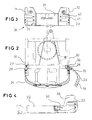
- a public works machine has a self-driving frame (2) and a turret (3) pivotally mounted on the frame (2).
- the invention is not limited to the types of machines as illustrated in FIG. Figure 1, but can adapt to a large number of public works machinery, that whether shovels, loaders or other, mounted on crawlers or pneumatic, very different jigs.
- the turret (3) comprises in the front part of a work equipment (4) formed in the form illustrated by an articulated work arm (5) presenting to its end a bucket (6).
- This turret (3) also has a cabin (7) to inside which takes place the driver to perform the different maneuvers.
- the turret (3) has an engine compartment (10) which encloses the heat engine, for example in the central part.
- the radiator of thermal engine cooling necessary for the proper functioning of the machine, and secondly all the pumps and distributors included in the hydraulic circuit of the machine.
- one of the wings also includes the battery of electric accumulators not shown.
- the rear part of the turret (3) also has a shield (20) intended to ensure the stability of the machine and to protect the turret, in particular the technical compartment (10).
- This shield is broken down into three parts, namely a central portion (21) which is fixed and which constitutes the extension of the base (22) of the turret.
- the shield also includes the two counterweights (23,24) object of the invention.
- the central portion (21) of the shield can be mounted articulated along a horizontal axis.
- the parts of the shield located at the level of the wings rear of the turret constitute counterweights that are pivotally mounted by relative to a vertical axis (26,27).
- this vertical axis is materialized by means of a hinge (28,29) located on the lateral faces (30,31) of the turret, substantially at the frontmost level of the technical compartment.
- each of these counterweights has a shape substantially square to form the rear angle of the turret.
- the outer shape of each of these counterweights can be curved to ensure an aesthetic exterior appearance.
- Each counterweight (23,24) has a first portion (35) attached to the hinge, located substantially at the base (22) of the turret. He is extended by a second portion (36) extending rearwardly and upwardly for constitute a shield of maximum area.
- each shield has openings through (40,41) to allow a better ventilation of the compartment technical.
- these lights (40,41) are located in planes horizontal and extend over a large part of the length of the counterweight (23).
- the counterweight (23) itself is secured to the hinge (28) by screwing (37) so as to be easier interchangeable in case it would be deformed following a shock.
- Holding in the closed position of the counterweight (23) forming an access door is provided by any known means, for example by a screwing located at its level. end (40).
- the geometry of the end (36) of the counterweight (23) lying on the face rear of the turret (3), has a recess for receiving the edge of the cover (42) covering the top of the technical compartment (10). In others, when the hood (42) is closed, it covers the top of the counterweight (23).
- FIG. 2 illustrates a turret viewed from above in which one of the counterweight (23) forming the access door is locked in the closed position, while the other (23) is open.
Landscapes
- Engineering & Computer Science (AREA)
- Mining & Mineral Resources (AREA)
- Civil Engineering (AREA)
- General Engineering & Computer Science (AREA)
- Structural Engineering (AREA)
- Component Parts Of Construction Machinery (AREA)
- Conveying And Assembling Of Building Elements In Situ (AREA)
- Soil Working Implements (AREA)
- Jib Cranes (AREA)
- Supply And Installment Of Electrical Components (AREA)
- Body Structure For Vehicles (AREA)
Claims (4)
- Tiefbaumaschine (1), umfassend einen Unterwagen (2), auf dem eine Drehbühne (3) montiert ist, wobei diese Drehbühne (3) nach vorne hin einen mit Gelenken versehenen Arbeitsarm (4) und nach hinten hin ein Technikabteil (10) und wenigstens ein Gegengewicht (21, 23, 24) aufweist, das sich in Höhe der hinteren Flügel (11, 12) der Drehbühne (3) befindet, dadurch gekennzeichnet, daß das oder die Gegengewicht(e) dazu fähig ist/sind, um eine im wesentlichen vertikale Achse (26, 27) zu schwenken, um Zugangstüren zum Technikabteil (10) zu bilden.
- Maschine nach Anspruch 1, dadurch gekennzeichnet, daß sich die vertikale Schwenkachse (26, 27) des Gegengewichts (23, 24) auf der Seitenfläche (30, 31) der Drehbühne (3) befindet.
- Maschine nach Anspruch 1, dadurch gekennzeichnet, daß jedes Gegengewicht einen Teil (36) aufweist, der sich über der Ebene des Scharniers (28) der Gelenkverbindung mit der Drehbühne (3) erstreckt.
- Maschine nach Anspruch 1, dadurch gekennzeichnet, daß die Gegengewichte (23, 24), welche Zugangstüren bilden, durchgehende Schlitze (40, 41) aufweisen, die dazu bestimmt sind, als Lüftungsöffnungen für das Technikabteil (10) zu dienen.
Applications Claiming Priority (2)
| Application Number | Priority Date | Filing Date | Title |
|---|---|---|---|
| FR9811977 | 1998-09-22 | ||
| FR9811977A FR2783538B1 (fr) | 1998-09-22 | 1998-09-22 | Engin de travaux publics sur lequel est montee une tourelle |
Publications (2)
| Publication Number | Publication Date |
|---|---|
| EP0989244A1 EP0989244A1 (de) | 2000-03-29 |
| EP0989244B1 true EP0989244B1 (de) | 2005-11-16 |
Family
ID=9530821
Family Applications (1)
| Application Number | Title | Priority Date | Filing Date |
|---|---|---|---|
| EP99420195A Expired - Lifetime EP0989244B1 (de) | 1998-09-22 | 1999-09-14 | Baumaschine mit einem schwenkbaren Oberwagen |
Country Status (4)
| Country | Link |
|---|---|
| EP (1) | EP0989244B1 (de) |
| AT (1) | ATE310129T1 (de) |
| DE (2) | DE69928341T2 (de) |
| FR (1) | FR2783538B1 (de) |
Family Cites Families (8)
| Publication number | Priority date | Publication date | Assignee | Title |
|---|---|---|---|---|
| FR2448500A1 (fr) * | 1979-02-07 | 1980-09-05 | Audureau Sa | Dispositif d'equilibrage d'un engin comportant un appareil de levage d'une charge en porte a faux |
| JPS55161740U (de) * | 1979-05-11 | 1980-11-20 | ||
| JP3572719B2 (ja) * | 1995-05-16 | 2004-10-06 | コベルコ建機株式会社 | 油圧作業機 |
| JP3078748B2 (ja) * | 1996-04-11 | 2000-08-21 | 新キャタピラー三菱株式会社 | 旋回体を備えた作業機械 |
| JP3510081B2 (ja) * | 1996-05-09 | 2004-03-22 | コベルコ建機株式会社 | 油圧作業機 |
| JPH09302722A (ja) * | 1996-05-15 | 1997-11-25 | Komatsu Ltd | パワーショベルのプロテクタ |
| JPH10338946A (ja) * | 1997-06-06 | 1998-12-22 | Kubota Corp | バックホウ |
| JPH1193219A (ja) * | 1997-09-24 | 1999-04-06 | Shin Caterpillar Mitsubishi Ltd | 油圧ショベルのカウンタウエイト装置 |
-
1998
- 1998-09-22 FR FR9811977A patent/FR2783538B1/fr not_active Expired - Fee Related
-
1999
- 1999-09-14 AT AT99420195T patent/ATE310129T1/de not_active IP Right Cessation
- 1999-09-14 EP EP99420195A patent/EP0989244B1/de not_active Expired - Lifetime
- 1999-09-14 DE DE69928341T patent/DE69928341T2/de not_active Expired - Lifetime
- 1999-09-14 DE DE0989244T patent/DE989244T1/de active Pending
Also Published As
| Publication number | Publication date |
|---|---|
| FR2783538B1 (fr) | 2000-10-20 |
| DE69928341D1 (de) | 2005-12-22 |
| DE69928341T2 (de) | 2006-06-01 |
| FR2783538A1 (fr) | 2000-03-24 |
| EP0989244A1 (de) | 2000-03-29 |
| ATE310129T1 (de) | 2005-12-15 |
| DE989244T1 (de) | 2000-11-02 |
Similar Documents
| Publication | Publication Date | Title |
|---|---|---|
| CA1127208A (en) | Lift truck cab having movable rear wall portion | |
| US5715615A (en) | Hydraulic working machine | |
| FR2595107A1 (fr) | Vehicule de type pelleteuse a pivotement complet a rayon reduit pour faciliter les operations dans un site resserre | |
| US20090230710A1 (en) | Rear accessible service hatch | |
| US5002332A (en) | Cabin construction of wheel loader | |
| US6508323B2 (en) | Hood for earthmoving machines | |
| FR3125638A1 (fr) | Ensemble de batteries pour un engin de travail | |
| EP0989244A1 (de) | Baumaschine mit einem schwenkbaren Oberwagen | |
| US20250206217A1 (en) | Work vehicle | |
| JP3980911B2 (ja) | 旋回型作業機械 | |
| WO2003062002A1 (fr) | Tablette arriere pour vehicule automobile dote d'un toit repliable | |
| US2737735A (en) | Hood mount and hoist mechanism for bulldozer blade | |
| JP7412306B2 (ja) | 乗用型草刈機 | |
| EP1103417B1 (de) | Bewegliche Fahrzeugebeleuchtungs- oder Signaleinrichtung | |
| JP3148637B2 (ja) | 建設作業機におけるボンネット支持構造 | |
| JP3489951B2 (ja) | スイング式油圧ショベル | |
| JP2000073401A (ja) | ホイルローダのボンネットフード | |
| JPH08834Y2 (ja) | コンバインの運転部構造 | |
| FR2852912A1 (fr) | Vehicule comportant un element d'habillage fixe sur un chassis pivotant | |
| JPS6322199Y2 (de) | ||
| JPH09309393A (ja) | 走行車両のフロントガード装置 | |
| EP4558440B1 (de) | Maschine zur handhabung einer last und/oder einer person | |
| CN213831885U (zh) | 一种中小型拖拉机用机罩后支架 | |
| JP2831895B2 (ja) | バックホウのボンネット構造 | |
| JP3310119B2 (ja) | 運転室内の収納ボックス |
Legal Events
| Date | Code | Title | Description |
|---|---|---|---|
| PUAI | Public reference made under article 153(3) epc to a published international application that has entered the european phase |
Free format text: ORIGINAL CODE: 0009012 |
|
| AK | Designated contracting states |
Kind code of ref document: A1 Designated state(s): AT BE CH CY DE DK ES FI FR GB GR IE IT LI LU MC NL PT SE |
|
| AX | Request for extension of the european patent |
Free format text: AL;LT;LV;MK;RO;SI |
|
| GBC | Gb: translation of claims filed (gb section 78(7)/1977) | ||
| 17P | Request for examination filed |
Effective date: 20000515 |
|
| TCAT | At: translation of patent claims filed | ||
| DET | De: translation of patent claims | ||
| AKX | Designation fees paid |
Free format text: AT BE CH CY DE DK ES FI FR GB GR IE IT LI LU MC NL PT SE |
|
| GRAP | Despatch of communication of intention to grant a patent |
Free format text: ORIGINAL CODE: EPIDOSNIGR1 |
|
| GRAS | Grant fee paid |
Free format text: ORIGINAL CODE: EPIDOSNIGR3 |
|
| GRAA | (expected) grant |
Free format text: ORIGINAL CODE: 0009210 |
|
| RAP1 | Party data changed (applicant data changed or rights of an application transferred) |
Owner name: VOLVO COMPACT EQUIPMENT SAS |
|
| AK | Designated contracting states |
Kind code of ref document: B1 Designated state(s): AT BE CH CY DE DK ES FI FR GB GR IE IT LI LU MC NL PT SE |
|
| PG25 | Lapsed in a contracting state [announced via postgrant information from national office to epo] |
Ref country code: NL Free format text: LAPSE BECAUSE OF FAILURE TO SUBMIT A TRANSLATION OF THE DESCRIPTION OR TO PAY THE FEE WITHIN THE PRESCRIBED TIME-LIMIT Effective date: 20051116 Ref country code: IE Free format text: LAPSE BECAUSE OF FAILURE TO SUBMIT A TRANSLATION OF THE DESCRIPTION OR TO PAY THE FEE WITHIN THE PRESCRIBED TIME-LIMIT Effective date: 20051116 Ref country code: FI Free format text: LAPSE BECAUSE OF FAILURE TO SUBMIT A TRANSLATION OF THE DESCRIPTION OR TO PAY THE FEE WITHIN THE PRESCRIBED TIME-LIMIT Effective date: 20051116 Ref country code: AT Free format text: LAPSE BECAUSE OF FAILURE TO SUBMIT A TRANSLATION OF THE DESCRIPTION OR TO PAY THE FEE WITHIN THE PRESCRIBED TIME-LIMIT Effective date: 20051116 |
|
| REG | Reference to a national code |
Ref country code: GB Ref legal event code: FG4D Free format text: NOT ENGLISH |
|
| REG | Reference to a national code |
Ref country code: CH Ref legal event code: EP |
|
| REG | Reference to a national code |
Ref country code: IE Ref legal event code: FG4D Free format text: LANGUAGE OF EP DOCUMENT: FRENCH |
|
| GBT | Gb: translation of ep patent filed (gb section 77(6)(a)/1977) |
Effective date: 20051130 |
|
| REF | Corresponds to: |
Ref document number: 69928341 Country of ref document: DE Date of ref document: 20051222 Kind code of ref document: P |
|
| PG25 | Lapsed in a contracting state [announced via postgrant information from national office to epo] |
Ref country code: SE Free format text: LAPSE BECAUSE OF FAILURE TO SUBMIT A TRANSLATION OF THE DESCRIPTION OR TO PAY THE FEE WITHIN THE PRESCRIBED TIME-LIMIT Effective date: 20060216 Ref country code: GR Free format text: LAPSE BECAUSE OF FAILURE TO SUBMIT A TRANSLATION OF THE DESCRIPTION OR TO PAY THE FEE WITHIN THE PRESCRIBED TIME-LIMIT Effective date: 20060216 Ref country code: DK Free format text: LAPSE BECAUSE OF FAILURE TO SUBMIT A TRANSLATION OF THE DESCRIPTION OR TO PAY THE FEE WITHIN THE PRESCRIBED TIME-LIMIT Effective date: 20060216 |
|
| PG25 | Lapsed in a contracting state [announced via postgrant information from national office to epo] |
Ref country code: ES Free format text: LAPSE BECAUSE OF FAILURE TO SUBMIT A TRANSLATION OF THE DESCRIPTION OR TO PAY THE FEE WITHIN THE PRESCRIBED TIME-LIMIT Effective date: 20060227 |
|
| PG25 | Lapsed in a contracting state [announced via postgrant information from national office to epo] |
Ref country code: PT Free format text: LAPSE BECAUSE OF FAILURE TO SUBMIT A TRANSLATION OF THE DESCRIPTION OR TO PAY THE FEE WITHIN THE PRESCRIBED TIME-LIMIT Effective date: 20060417 |
|
| NLV1 | Nl: lapsed or annulled due to failure to fulfill the requirements of art. 29p and 29m of the patents act | ||
| REG | Reference to a national code |
Ref country code: IE Ref legal event code: FD4D |
|
| PLBE | No opposition filed within time limit |
Free format text: ORIGINAL CODE: 0009261 |
|
| STAA | Information on the status of an ep patent application or granted ep patent |
Free format text: STATUS: NO OPPOSITION FILED WITHIN TIME LIMIT |
|
| PG25 | Lapsed in a contracting state [announced via postgrant information from national office to epo] |
Ref country code: MC Free format text: LAPSE BECAUSE OF NON-PAYMENT OF DUE FEES Effective date: 20060930 Ref country code: LI Free format text: LAPSE BECAUSE OF NON-PAYMENT OF DUE FEES Effective date: 20060930 Ref country code: CH Free format text: LAPSE BECAUSE OF NON-PAYMENT OF DUE FEES Effective date: 20060930 Ref country code: BE Free format text: LAPSE BECAUSE OF NON-PAYMENT OF DUE FEES Effective date: 20060930 |
|
| 26N | No opposition filed |
Effective date: 20060817 |
|
| REG | Reference to a national code |
Ref country code: CH Ref legal event code: PL |
|
| BERE | Be: lapsed |
Owner name: VOLVO COMPACT EQUIPMENT SAS Effective date: 20060930 |
|
| PG25 | Lapsed in a contracting state [announced via postgrant information from national office to epo] |
Ref country code: LU Free format text: LAPSE BECAUSE OF NON-PAYMENT OF DUE FEES Effective date: 20060914 |
|
| PG25 | Lapsed in a contracting state [announced via postgrant information from national office to epo] |
Ref country code: CY Free format text: LAPSE BECAUSE OF FAILURE TO SUBMIT A TRANSLATION OF THE DESCRIPTION OR TO PAY THE FEE WITHIN THE PRESCRIBED TIME-LIMIT Effective date: 20051116 |
|
| REG | Reference to a national code |
Ref country code: FR Ref legal event code: PLFP Year of fee payment: 17 |
|
| PGFP | Annual fee paid to national office [announced via postgrant information from national office to epo] |
Ref country code: GB Payment date: 20150909 Year of fee payment: 17 Ref country code: DE Payment date: 20150909 Year of fee payment: 17 |
|
| PGFP | Annual fee paid to national office [announced via postgrant information from national office to epo] |
Ref country code: IT Payment date: 20150917 Year of fee payment: 17 |
|
| PGFP | Annual fee paid to national office [announced via postgrant information from national office to epo] |
Ref country code: FR Payment date: 20150930 Year of fee payment: 17 |
|
| REG | Reference to a national code |
Ref country code: DE Ref legal event code: R119 Ref document number: 69928341 Country of ref document: DE |
|
| GBPC | Gb: european patent ceased through non-payment of renewal fee |
Effective date: 20160914 |
|
| REG | Reference to a national code |
Ref country code: FR Ref legal event code: ST Effective date: 20170531 |
|
| PG25 | Lapsed in a contracting state [announced via postgrant information from national office to epo] |
Ref country code: FR Free format text: LAPSE BECAUSE OF NON-PAYMENT OF DUE FEES Effective date: 20160930 Ref country code: GB Free format text: LAPSE BECAUSE OF NON-PAYMENT OF DUE FEES Effective date: 20160914 Ref country code: DE Free format text: LAPSE BECAUSE OF NON-PAYMENT OF DUE FEES Effective date: 20170401 |
|
| PG25 | Lapsed in a contracting state [announced via postgrant information from national office to epo] |
Ref country code: IT Free format text: LAPSE BECAUSE OF NON-PAYMENT OF DUE FEES Effective date: 20160914 |