EP0988909B1 - Vorrichtung zum steigenden Niederdruck-Giessen von Metallen, insbesondere Leichtmetallen - Google Patents
Vorrichtung zum steigenden Niederdruck-Giessen von Metallen, insbesondere Leichtmetallen Download PDFInfo
- Publication number
- EP0988909B1 EP0988909B1 EP99117642A EP99117642A EP0988909B1 EP 0988909 B1 EP0988909 B1 EP 0988909B1 EP 99117642 A EP99117642 A EP 99117642A EP 99117642 A EP99117642 A EP 99117642A EP 0988909 B1 EP0988909 B1 EP 0988909B1
- Authority
- EP
- European Patent Office
- Prior art keywords
- guide
- mould
- sealing plug
- sprue
- mold
- Prior art date
- Legal status (The legal status is an assumption and is not a legal conclusion. Google has not performed a legal analysis and makes no representation as to the accuracy of the status listed.)
- Expired - Lifetime
Links
- 238000005266 casting Methods 0.000 title claims abstract description 36
- 229910052751 metal Inorganic materials 0.000 title claims description 7
- 239000002184 metal Substances 0.000 title claims description 7
- 150000002739 metals Chemical class 0.000 title claims description 5
- 239000004576 sand Substances 0.000 claims abstract description 34
- 239000000155 melt Substances 0.000 claims abstract description 33
- 238000005058 metal casting Methods 0.000 claims abstract description 4
- 238000007789 sealing Methods 0.000 claims description 35
- 239000002245 particle Substances 0.000 claims description 15
- 238000000465 moulding Methods 0.000 claims description 7
- 239000011796 hollow space material Substances 0.000 abstract 2
- 239000003110 molding sand Substances 0.000 description 15
- 230000007704 transition Effects 0.000 description 3
- 238000005299 abrasion Methods 0.000 description 2
- 230000015572 biosynthetic process Effects 0.000 description 2
- 238000001816 cooling Methods 0.000 description 2
- 238000002360 preparation method Methods 0.000 description 2
- 229910000838 Al alloy Inorganic materials 0.000 description 1
- 230000000903 blocking effect Effects 0.000 description 1
- 230000001419 dependent effect Effects 0.000 description 1
- 238000009499 grossing Methods 0.000 description 1
- 238000004519 manufacturing process Methods 0.000 description 1
- 239000000463 material Substances 0.000 description 1
- 238000002844 melting Methods 0.000 description 1
- 230000008018 melting Effects 0.000 description 1
- 239000000203 mixture Substances 0.000 description 1
- 238000009417 prefabrication Methods 0.000 description 1
- 230000000630 rising effect Effects 0.000 description 1
- 230000003746 surface roughness Effects 0.000 description 1
- 230000002123 temporal effect Effects 0.000 description 1
Images


Classifications
-
- B—PERFORMING OPERATIONS; TRANSPORTING
- B22—CASTING; POWDER METALLURGY
- B22D—CASTING OF METALS; CASTING OF OTHER SUBSTANCES BY THE SAME PROCESSES OR DEVICES
- B22D18/00—Pressure casting; Vacuum casting
- B22D18/04—Low pressure casting, i.e. making use of pressures up to a few bars to fill the mould
Definitions
- the invention relates to a device for increasing Low pressure casting of metals, especially light metals, in divided sand molds with a sprue in one of the two forms to which the pouring tube of a melt container is connectable and the one with the lowest area of the mold cavity, and with an in the form of integrated stopper, which after the Filling the mold cavity using an external, in the Form engaging drive can be brought into the closed position is.
- the melt With the increasing pouring of metals, the melt becomes the melt container or a holding furnace under Overpressurized to the melt over the pouring tube and press the gate into the mold cavity.
- To the filling of the mold in the pouring tube and in the pouring of the Formed melt column are interrupted to the transport the cast mold and the next one To be able to dock the mold to the pouring tube.
- the Melt in the pouring tube Before that, the Melt in the pouring tube to be reset.
- Furthermore are on the form to make arrangements for the sprue is closed during further transport of the mold, at least until the melt is in the pouring gate is frozen. This is done, for example, by moving it the mold on cooling plates or by using the mold carried cooling plates.
- Both known versions have the Advantage that the mold does not contain any components that are not of the same type, because the plug from the same molding sand how the mold itself exists and consequently with the molding sand the shape can be worked up.
- the closure is completely uncontrolled and the quality of the closure of the dimensional stability, which is due to the drive on the Molding sand acting expressiveness and the temporal Force gradient is dependent.
- it is not ensures that there is actually an intact closed Grafting forms and the shape is not sideways of the expressed graft breaks out.
- the invention is based on this prior art the task of creating a device while maintaining the pure composition the sand mold a perfect closure in the area the pouring is possible and also with high casting performance and large gate cross sections the quality of the Closure is reproducibly preserved and finally the danger of the introduction of molding sand particles into the melt is minimized.
- This object is achieved in that between the gate and the mold cavity connecting these Pouring channel is arranged at an angle to the sprue, and that the sealing plug is formed as a sand molding and in a molded guide between the mold an open position and a closed position in which he the Pouring channel closes and the metallostatic pressure of the Melt in the form perpendicular to the guide on the sealing plug works, is movable.
- the plug is preformed as sand moldings.
- a guide for the sealing plug on the other hand, a pouring channel is formed at an angle to the sprue, namely in the area of the mold parting plane Shape.
- the pouring channel is preferably at right angles or at a steep obtuse angle to the flow direction in the gate. With high castings, that is accordingly The pouring channel must also go deep into this form be shaped accordingly deep. The final one The cross section of the pouring channel can then be inserted Core be determined.
- the melt is poured into the mold redirected the pouring channel.
- the plug In the area of the redirection Guide arranged with the plug, whereby the plug first in the transition between Opening and sprue-releasing opening position located.
- After filling the mold it becomes a sand molding trained stopper by means of in the Form engaging external drive within the guide moved to the closed position in which the transition between the gate and the pouring channel from the plug is misplaced.
- the metallostatic acts in the closed position Pressure of the form across the guide on the Sealing plug so that it remains in its position.
- the sealing plug is a separate molded part, there is only minimal abrasion on the guide or Sand moldings themselves, so that the risk of procrastination of molding sand particles in the pouring tube when resetting the melt is very low.
- the Sealing plugs are basically made of the same molding sand Manufacture like the mold itself, so that when it is processed of the molding sand is also worked up. Due to the separate prefabrication, the hardness of the Optimize sand molding according to the intended use.
- the plug is in the Opening position held self-locking in the guide.
- the Self-locking can be done by a correspondingly tight fit supported by plugs and guide, if necessary due to frictional forces due to surface roughness realize.
- the sealing plug can also be poured into the sprue Guide inserted and for example a step or The like.
- the plug becomes under the buoyancy of the melt in the Opening position raised, in which it seals in the guide, for example against a ring step or through conical formation of the guide against the guide surface seals.
- the sand moldings forming the sealing plug also Core sand must be made. In both cases, you can surface smoothing by applying a size recommend.
- the guide is designed as a sleeve made of core sand and is inserted into preformed receptacles of the form, the sleeve opening radially into the pouring channel Has recesses for the melt transfer that by means of the sealing plug inserted in the can are lockable.
- the rifle By training the guide as a can made of core sand can better guide properties for the plug realize. Furthermore, this rifle greater strength, so that the on the plug acting thrust no danger to the Represent the guide bush. Furthermore, the rifle can same external dimensions and corresponding recordings in terms of arrangement and size of the recesses for the transfer of the melt to the respective Conditions to be adjusted. Because the can made of core sand exists, it also provides the usual sand preparation process is not a foreign body.
- the guide-whether formed directly in the molding sand or as a core of core sand - extends from the Casting mold over the mold parting plane up to the other form, so that it is ensured that the cross pouring channel lying at the gate can be completely closed is.
- the core sand can has the advantage that even with an offset of the shapes in the parting plane a linear, ensures smooth guidance for the sealing plug is.
- the guide is for the Sealing plug coaxial with that essentially vertically running sprue and the pouring channel approximately formed horizontally in the shape below.
- the guide is then one with the Guide coaxial bore for the engagement of the drive of the sealing plug arranged from above. The The drive therefore engages from the one opposite the gate Page in the form.
- the pouring channel runs approximately horizontally about vertical and is the plug with his Guide parallel above the gate and across the Pouring channel arranged.
- the flows Melt the mold first horizontally and then deflected vertically into the pouring channel, which after filling the shape of the plug which can be moved transversely to it is relocated.
- the via a central gate with a star shape perpendicular to it arranged pouring channels are filled Guide with the sealing plug coaxial with the Arranged sprue and put the pouring channels on this Guide so that after filling all the mold cavities the pouring channels with a single plug can be relocated.
- the drive for the plug is advantageous a pressure cylinder, the piston rod in a molded or subsequently mechanically inserted Hole engages in the shape.
- the drive can be preferably control so that the piston rod of the drive before filling the mold into a stopper against the pressure of the melt in the open position supporting standby position is movable.
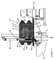
- a casting table 1 shown, which may be by means of a lifting cylinder 2 is tiltable.
- a Melt container 3 optionally in the form of a holding furnace arranged.
- immersed Pouring tube 4 In the located in the melt container 3 and melt under pressure is immersed Pouring tube 4, which opens out on the casting table.
- the sand mold 5 is arranged, which at Embodiment shown from an upper box shape 6 and a lower box shape 7, in which a further Core 8 is inserted. Between the top box shape 6 and the lower box mold 7 and the mold core 8 is the Mold cavity 9 formed.
- the top box shape 6 has further in the mold parting plane 10 to the mold cavity 9 subsequent risers 11 on.
- the bottom box shape 7 has on one side a essential vertical sprue 12, which is about at right angles a pouring channel 13 connects in the area the deepest point of the mold cavity 9 opens into this.
- the pouring channel molded in from the mold parting plane 10 13 is in this embodiment by a core 14 inserted from the mold parting plane upwards limited.
- a core 14 is only with very high castings with a correspondingly deep gate necessary. at flat castings, the pouring channel 13 can directly in the mold parting plane.
- a guide 15 In the shape of a guide 15 is also molded, the in the embodiment shown from an inserted Box is formed, which in turn is made from core sand is. The leadership can also in the Molding sand of the mold can be formed.
- the guide designed as a sleeve 15 a radially open window 16 through which the Interior of the guide 15 with the pouring channel 13 in connection stands.
- a plug 17 which as Shaped body is formed from molding sand or core sand.
- the Guide 15 and the plug 17 are so on top of each other adjusted that the plug 17 self-locking is held in the open position shown in Fig. 1. If necessary, it can also be glued in place.
- downstream of the sealing plug 17 is a particle filter in the guide 15 18 used.
- the device also has an external drive 19, which in the embodiment shown is designed as a pressure medium cylinder, whose piston rod 20 in a coaxial with the sprue 12 Engage hole 21 in the upper box mold 6 can.
- Fig. 1 shows the starting position before casting, in the the melt column standing in the pouring tube 4 is reset and is otherwise depressurized.
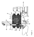
- the piston rod 20 Before the start of the casting process the piston rod 20 is extended so far that it is in System comes on the plug 17 and this against holds the melt pressure in position (Fig. 2). Subsequently the casting process begins.
- the melt rises from the Pouring tube 4 in the sprue and the guide 15 and from there via the window 16 and the pouring channel 13 into the mold cavity 9.
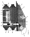
- the drive 19 controlled and moves the piston rod 20 to Plug 21 down until the window 16 in the Guide 15 is covered (Fig. 3).
- the sealing plug can 17 also sit with a game in the leadership and in the Starting position, for example, on the particle filter 18 rest.
- the plug 17 is raised by the buoyancy force, until he releases the recess 16 and in the Opening position on a ring step on the guide or at conical formation of the leadership sealing against the leadership supported. This will cause the air cushion above the Melting level minimized and in the narrowed filter cross section accelerated melt front calms down.
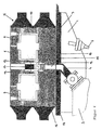
- Fig. 5 shows a slightly modified compared to Figs. 1 to 4 Embodiment for flatter castings, where for identical parts, the reference numerals of FIGS. 1 to 4 are taken over.
- the guide 15 is here again made as a preformed sleeve from core sand, which with is provided with a plurality of radially opening windows 16, one of which is aligned with the pouring channel 13.
- the guide 15 in turn receives the plug 17 and also on its opposite side the particle filter 18.
- the top box shape 6 has one appropriate recording so that after adding the Upper box positioned the sleeve 15 forming the guide is.
- the gate 6 has the shape 5 several discrete mold cavities 9, as in multiple molds are common.
- the gate is 12 centrally located and go from this essentially radially from the pouring channels 13.
- the Guide 15 has at least two diametrically opposite Window 16, each with a pouring channel 13 correlate. The way it works is the same as with 1 to 4 with the difference that both mold cavity 9 via the gate 12 and the interior the guide 15 and the two pouring channels 13 simultaneously be filled.
- the Plug 17 moved down until he both Window 16 moved.
- Fig. 7 shows an embodiment of a form 5 with four discrete mold cavities 9 and a central one Sprue on which the pouring channels run perpendicular to it 13 start. Is coaxial with the sprue again a guide 15 in the form of a sleeve made of core sand four windows are used for each pouring channel 13. In the Guide 15, the plug 17 is slidable.
- the plug is 15 arranged in the closed position so that the one acting on it metallostatic pressure of the form perpendicular to the guide acts, the plug so equally in the Guide tense, so that an always effective closure given is.
Landscapes
- Engineering & Computer Science (AREA)
- Mechanical Engineering (AREA)
- Molds, Cores, And Manufacturing Methods Thereof (AREA)
- Manufacture Of Alloys Or Alloy Compounds (AREA)
Description
- Fig. 1 bis 4
- eine schematische Ansicht einer ersten Ausführungsform in verschiedenen Positionen beim Gießen;
- Fig. 5
- eine vergrößerte Teilansicht ähnlich Fig. 1 in einer abgewandelten Ausführung;
- Fig. 6
- eine der Fig. 5 entsprechende Ansicht einer weiteren Ausführungsform;
- Fig. 7
- eine Draufsicht auf eine weitere Ausführungsform;
- Fig. 8
- eine Ausführungsform der Vorrichtung mit senkrecht stehenden Formen.
Claims (19)
- Vorrichtung zum steigenden Niederdruck-Gießen von Metallen, insbesondere Leichtmetallen, in geteilten Sandformen (5, 6, 7) mit einem Einguß (12) in einer der beiden Formen (7), an den das Gießrohr (4) eines Schmelzebehälters (3) anschließbar ist und der mit dem tiefsten Bereich des Formhohlraums (9) in Verbindung steht, und mit einem in die Form (5) integrierten Verschlußstopfen (17) der nach dem Füllen des Formhohlraums (9) mittels eines externen, in die Form eingreifenden Antriebs (19) in die Schließstellung bringbar ist, dadurch gekennzeichnet, daß zwischen dem Einguß (12) und dem Formhohlraum (9) ein diese verbindender Gießkanal (13) winklig zu dem Einguß angeordnet ist, und daß der Verschlußstopfen (17) als Sandformkörper ausgebildet und in einer eingeformten Führung (15) der Form (5) zwischen einer Öffnungslage und einer Schließlage, in der er den Gießkanal verschließt und der metallostatische Druck der Schmelze in der Form senkrecht zur Führung (15) auf den Verschlußstopfen (17) wirkt, verschiebbar ist.
- Vorrichtung nach Anspruch 1, dadurch gekennzeichnet, daß der Verschlußstopfen (17) in der Öffnungslage selbsthemmend in der Führung (15) gehalten ist.
- Vorrichtung nach Anspruch 1, dadurch gekennzeichnet, daß bei horizontal liegenden Formen (5) der Verschlußstopfen (17) mit Spiel in die Führung (15) eingelegt ist und beim Füllen der Form unter der Auftriebskraft der Schmelze in die Öffnungslage anhebbar ist, in der er gegen die Führung dichtet.
- Vorrichtung nach einem der Ansprüche 1 bis 3, dadurch gekennzeichnet, daß der Sandformkörper aus Formsand hergestellt ist.
- Vorrichtung nach einem der Ansprüche 1 bis 3, dadurch gekennzeichnet, daß der Sandformkörper aus Kernsand hergestellt ist.
- Vorrichtung nach Anspruch 4 oder 5, dadurch gekennzeichnet, daß der Sandformkörper mit einer Schlichte geglättet ist.
- Vorrichtung nach einem der Ansprüche 1 bis 6, dadurch gekennzeichnet, daß die Führung als Büchse (15) aus Kernsand ausgebildet und in vorgeformte Aufnahmen der Form (5) eingesetzt ist, und daß die Büchse sich radial in den Gießkanal (13) öffnende Aussparungen (16) für den Schmelzeübertritt aufweist, die mittels des in die Büchse (15) eingesetzten Verschlußstopfens (17) verschließbar sind.
- Vorrichtung nach Anspruch 7, dadurch gekennzeichnet, daß die Führung (15) sich von der den Einguß (12) aufweisenden Form (7) über die Formtrennebene (10) bis in die andere Form (6) erstreckt.
- Vorrichtung nach Anspruch 7 oder 8, dadurch gekennzeichnet, daß die Büchse (15) in einer zugekehrten Aufnahmen beider Formen (6, 7) angeordnet ist.
- Vorrichtung nach einem der Ansprüche 1 bis 9, dadurch gekennzeichnet, daß stromabwärts des Verschlußstopfens (17) ein Partikelfilter (18) angeordnet ist.
- Vorrichtung nach einem der Ansprüche 1 bis 10, dadurch gekennzeichnet, daß der Partikelfilter (18) am Schmelzezulauf der Büchse (15) angeordnet ist.
- Vorrichtung nach Anspruch 11, dadurch gekennzeichnet, daß der Partikelfilter (18) in die Büchse (15) eingesetzt ist.
- Vorrichtung nach einem der Ansprüche 1 bis 12, dadurch gekennzeichnet, daß bei horizontal liegenden Formen (6, 7) die Führung (15) für den Verschlußstopfen (17) gleichachsig mit dem im wesentlichen vertikal verlaufenden Einguß und der Gießkanal (13) etwa horizontal in der unten liegenden Form (7) ausgebildet sind.
- Vorrichtung nach Anspruch 13, dadurch gekennzeichnet, daß in der oben liegenden Form (6) eine mit der Führung (15) gleichachsige Bohrung (21) angeordnet ist, in die der Antrieb (19, 20) für den Verschlußstopfen (17) von oben her eingreift.
- Vorrichtung nach einem der Ansprüche 1 bis 12, dadurch gekennzeichnet, daß bei vertikal stehenden Formen (5) mit seitlichem Anguß und horizontal liegendem Einguß (12) der Gießkanal (25) etwa vertikal verläuft und die Führung (15) mit dem Verschlußstopfen (17) etwa parallel oberhalb des Eingusses (12) und quer zum Gießkanal (25) angeordnet ist.
- Vorrichtung nach Anspruch 15, dadurch gekennzeichnet daß in der den Einguß (12) aufweisenden Form und parallel zu diesem eine mit der Führung (15) für den Verschlußstopfen (17) gleichachsige Bohrung (24) angeordnet ist, in die der Antrieb (19, 20) für den Verschlußstopfen von der Seite des Angusses her eingreift.
- Vorrichtung nach einem der Ansprüche 1 bis 16, dadurch gekennzeichnet, daß bei Formen (5) mit mehreren diskreten Formhohlräumen (9) und zentralem Einguß (12), der über sternförmig angeordnete Gießkanäle (13) mit den Formhohlräumen (9) verbunden ist, die Führung (15) mit dem Verschlußstopfen (17) gleichachsig mit dem Einguß (12) angeordnet ist und die Gießkanäle (13) an der Führung (15) ansetzen.
- Vorrichtung nach einem der Ansprüche 1 bis 17, dadurch gekennzeichnet, daß der Antrieb für den Verschlußstopfen (17) ein Druckmittelzylinder (19) ist, dessen Kolbenstange (20) in die Form (5) einfahrbar ist.
- Vorrichtung nach Anspruch 18, dadurch gekennzeichnet, daß die Kolbenstange (20) des Antriebs (19) vor dem Füllen der Form in eine den Verschlußstopfen (17) gegen den Druck der Schmelze in der Öffnungslage (12) abstützende Bereitschaftsstellung verfahrbar ist.
Applications Claiming Priority (2)
| Application Number | Priority Date | Filing Date | Title |
|---|---|---|---|
| DE19843285 | 1998-09-22 | ||
| DE19843285A DE19843285A1 (de) | 1998-09-22 | 1998-09-22 | Vorrichtung zum steigenden Niederdruck-Gießen von Metallen, insbesondere Leichtmetallen |
Publications (2)
| Publication Number | Publication Date |
|---|---|
| EP0988909A1 EP0988909A1 (de) | 2000-03-29 |
| EP0988909B1 true EP0988909B1 (de) | 2003-07-16 |
Family
ID=7881736
Family Applications (1)
| Application Number | Title | Priority Date | Filing Date |
|---|---|---|---|
| EP99117642A Expired - Lifetime EP0988909B1 (de) | 1998-09-22 | 1999-09-08 | Vorrichtung zum steigenden Niederdruck-Giessen von Metallen, insbesondere Leichtmetallen |
Country Status (5)
| Country | Link |
|---|---|
| US (1) | US6460603B1 (de) |
| EP (1) | EP0988909B1 (de) |
| JP (1) | JP2000094116A (de) |
| AT (1) | ATE245072T1 (de) |
| DE (2) | DE19843285A1 (de) |
Families Citing this family (7)
| Publication number | Priority date | Publication date | Assignee | Title |
|---|---|---|---|---|
| AT511300B1 (de) | 2011-02-09 | 2019-03-15 | Fill Gmbh | Giessverfahren sowie giessanlage zur herstellung von werkstücken |
| CN102699310B (zh) * | 2012-06-08 | 2014-06-11 | 天津立中车轮有限公司 | 一种低压铸造轮毂排气系统及其铸造方法 |
| US20190240728A1 (en) * | 2015-02-19 | 2019-08-08 | Mei Ta Industrial Co., Ltd | Negative pressure updraught pouring device and method |
| US10421116B2 (en) | 2017-07-05 | 2019-09-24 | L.E. Jones Company | Method of casting valve seat inserts and casting apparatus |
| CN112872327B (zh) * | 2021-01-12 | 2022-03-01 | 重庆擎一模具制造有限公司 | 一种低压铸造模 |
| CN115673286B (zh) * | 2022-11-09 | 2023-08-18 | 厦门鼎松五金工业有限公司 | 一种管件预埋压铸铝工艺及其成型设备 |
| CN118650145B (zh) * | 2024-08-22 | 2024-11-29 | 兴化市精锐机械有限公司 | 一种水泵盖体浇铸成型装置 |
Family Cites Families (10)
| Publication number | Priority date | Publication date | Assignee | Title |
|---|---|---|---|---|
| DE1105115B (de) * | 1957-06-03 | 1961-04-20 | Griffin Wheel Company | Druckgiessanlage |
| US3329201A (en) * | 1964-12-11 | 1967-07-04 | Harbison Walker Refractories | Pouring tube for pressure pouring apparatus |
| DE2437734A1 (de) * | 1974-08-06 | 1976-02-26 | Merkur Gmbh Metallwerk | Niederdruck-giessvorrichtung fuer magnesium |
| CA2125276A1 (en) * | 1991-12-07 | 1993-06-24 | Alloy Technologies Limited | Casting of light metal alloys |
| EP0599768B1 (de) * | 1992-11-20 | 1998-05-13 | Agustin Arana Erana | Vorrichtung zum Giessen von Nichteisenmetallen in Sandformen mittels Nachdruck |
| RU2127172C1 (ru) * | 1994-05-27 | 1999-03-10 | Георг Фишер Диса А/С | Способ закрытия входа в литейную форму после неграфитационного литья нежелезного сплава в сырые литейные формы рядной устанвоки (варианты) |
| DK77694A (da) * | 1994-06-29 | 1995-12-30 | Dansk Ind Syndikat | Fremgangsmåde og indretning til ved udstøbning mod tyngdekraften af støbeforme, især vådsandforme, med navnlig letoxiderbare metaller eller metallegeringer af afslutte støbeprocessen |
| JP3614598B2 (ja) * | 1997-02-07 | 2005-01-26 | ヤマハ発動機株式会社 | 鋳造装置用フィルタ及び鋳造装置 |
| DE19720057A1 (de) * | 1997-05-14 | 1998-11-19 | Wagner Heinrich Sinto Masch | Verfahren und Vorrichtung zum steigenden Gießen in Sand-Gießformen |
| DE19807623A1 (de) * | 1998-02-21 | 1999-08-26 | Georg Fischer Disa Ag | Niederdruck-Gießverfahren für Leichtmetalle, insbesondere Aluminium |
-
1998
- 1998-09-22 DE DE19843285A patent/DE19843285A1/de not_active Withdrawn
-
1999
- 1999-09-08 AT AT99117642T patent/ATE245072T1/de not_active IP Right Cessation
- 1999-09-08 EP EP99117642A patent/EP0988909B1/de not_active Expired - Lifetime
- 1999-09-08 DE DE59906288T patent/DE59906288D1/de not_active Expired - Fee Related
- 1999-09-21 JP JP11267307A patent/JP2000094116A/ja not_active Withdrawn
- 1999-09-22 US US09/401,808 patent/US6460603B1/en not_active Expired - Fee Related
Also Published As
| Publication number | Publication date |
|---|---|
| JP2000094116A (ja) | 2000-04-04 |
| EP0988909A1 (de) | 2000-03-29 |
| ATE245072T1 (de) | 2003-08-15 |
| US6460603B1 (en) | 2002-10-08 |
| DE19843285A1 (de) | 2000-03-23 |
| DE59906288D1 (de) | 2003-08-21 |
Similar Documents
| Publication | Publication Date | Title |
|---|---|---|
| DE69228998T2 (de) | Giessen von leichtmetall-legierungen | |
| CH654768A5 (de) | Entgasungsvorrichtung an einer druck- oder spritzgiessform. | |
| DE2850229A1 (de) | Druckgussmaschine | |
| EP2945760B1 (de) | Giessform zur herstellung von gussteilen, insbesondere zylinderblöcken und zylinderköpfen, mit funktionaler anbindung des speisers | |
| EP3570992B1 (de) | Giessform zum giessen von komplex geformten gussteilen und verwendung einer solchen giessform | |
| DE3101841A1 (de) | Verfahren zum einspritzen geschmolzenen metalles in einer vertikalen druckgussmaschine | |
| DE102012107363A1 (de) | Dreiplattendruckgusswerkzeug mit Angusssystem sowie Angusssystem | |
| EP2844409A1 (de) | VERFAHREN ZUM GIEßEN EINES MIT MINDESTENS EINER DURCHGANGSÖFFNUNG VERSEHENEN GUSSTEILS | |
| EP0988909B1 (de) | Vorrichtung zum steigenden Niederdruck-Giessen von Metallen, insbesondere Leichtmetallen | |
| DE2361934A1 (de) | Speicherform fuer den niederdruckguss | |
| DE2330547A1 (de) | Spritzgussvorrichtung | |
| DE10392988T5 (de) | Metallgussform | |
| EP3697554B1 (de) | Druckgussform zum giessen von zylinderkurbelgehäusen oder kurbelgehäuseunterteilen | |
| DE19834553A1 (de) | Verfahren und Vorrichtung zum steigenden Gießen von Leichtmetall | |
| DE68901902T2 (de) | Verfahren zur formenherstellung von gegenstaenden, mittel im hinblick auf die durchfuehrung dieses verfahrens und beabsichtigte einrichtungen fuer diese mittel. | |
| DE69610550T2 (de) | Verfahren und vorrichtung zum pressgissen | |
| EP1050356A1 (de) | Verfahren und Vorrichtung zum Füllen von Giessformen mit flüssigen Metallen | |
| EP0937525A1 (de) | Niederdruck-Giessverfahren für Leichtmetalle, insbesondere Aluminium, und Vorrichtung zur Durchführung des Verfahrens | |
| EP0894557A1 (de) | Verfahren zum Formgiessen und Giessform für ein solches Verfahren | |
| DE69108306T2 (de) | Verfahren, Giessform und Vorrichtung zum mehrstufigen Niederdruckgiessen von Metall. | |
| EP3053672A1 (de) | Druckgiessen von Federbeinstützen | |
| DE2846512A1 (de) | Maschine zum druckgiessen von metallen, insbesondere legierten eisenmetallen (stahl) | |
| DE10033903C1 (de) | Verfahren und Vorrichtung zum steigenden Giessen mit einer Giessform mit untenliegender Eingussöffnung mit einem Schieberverschluss | |
| DE10045594B4 (de) | Verfahren und Vorrichtung zum Gießen von Hohlkörpern | |
| DE3817688A1 (de) | Kokillengussverfahren, insbesondere fuer metalle, sowie vorrichtung und giessform zur verwendung bei diesem verfahren |
Legal Events
| Date | Code | Title | Description |
|---|---|---|---|
| PUAI | Public reference made under article 153(3) epc to a published international application that has entered the european phase |
Free format text: ORIGINAL CODE: 0009012 |
|
| AK | Designated contracting states |
Kind code of ref document: A1 Designated state(s): AT BE CH CY DE DK ES FI FR GB GR IE IT LI LU MC NL PT SE |
|
| AX | Request for extension of the european patent |
Free format text: AL;LT;LV;MK;RO;SI |
|
| AKX | Designation fees paid | ||
| 17P | Request for examination filed |
Effective date: 20000928 |
|
| RBV | Designated contracting states (corrected) |
Designated state(s): AT BE CH CY DE DK ES FI FR GB GR IE IT LI LU MC NL PT SE |
|
| GRAH | Despatch of communication of intention to grant a patent |
Free format text: ORIGINAL CODE: EPIDOS IGRA |
|
| RAP1 | Party data changed (applicant data changed or rights of an application transferred) |
Owner name: DISA INDUSTRIES A/S |
|
| GRAH | Despatch of communication of intention to grant a patent |
Free format text: ORIGINAL CODE: EPIDOS IGRA |
|
| GRAA | (expected) grant |
Free format text: ORIGINAL CODE: 0009210 |
|
| AK | Designated contracting states |
Designated state(s): AT BE CH CY DE DK ES FI FR GB GR IE IT LI LU MC NL PT SE |
|
| PG25 | Lapsed in a contracting state [announced via postgrant information from national office to epo] |
Ref country code: NL Free format text: LAPSE BECAUSE OF FAILURE TO SUBMIT A TRANSLATION OF THE DESCRIPTION OR TO PAY THE FEE WITHIN THE PRESCRIBED TIME-LIMIT Effective date: 20030716 Ref country code: IT Free format text: LAPSE BECAUSE OF FAILURE TO SUBMIT A TRANSLATION OF THE DESCRIPTION OR TO PAY THE FEE WITHIN THE PRESCRIBED TIME-LIMIT;WARNING: LAPSES OF ITALIAN PATENTS WITH EFFECTIVE DATE BEFORE 2007 MAY HAVE OCCURRED AT ANY TIME BEFORE 2007. THE CORRECT EFFECTIVE DATE MAY BE DIFFERENT FROM THE ONE RECORDED. Effective date: 20030716 Ref country code: IE Free format text: LAPSE BECAUSE OF FAILURE TO SUBMIT A TRANSLATION OF THE DESCRIPTION OR TO PAY THE FEE WITHIN THE PRESCRIBED TIME-LIMIT Effective date: 20030716 Ref country code: GB Free format text: LAPSE BECAUSE OF FAILURE TO SUBMIT A TRANSLATION OF THE DESCRIPTION OR TO PAY THE FEE WITHIN THE PRESCRIBED TIME-LIMIT Effective date: 20030716 Ref country code: FR Free format text: LAPSE BECAUSE OF FAILURE TO SUBMIT A TRANSLATION OF THE DESCRIPTION OR TO PAY THE FEE WITHIN THE PRESCRIBED TIME-LIMIT Effective date: 20030716 Ref country code: FI Free format text: LAPSE BECAUSE OF FAILURE TO SUBMIT A TRANSLATION OF THE DESCRIPTION OR TO PAY THE FEE WITHIN THE PRESCRIBED TIME-LIMIT Effective date: 20030716 Ref country code: ES Free format text: LAPSE BECAUSE OF FAILURE TO SUBMIT A TRANSLATION OF THE DESCRIPTION OR TO PAY THE FEE WITHIN THE PRESCRIBED TIME-LIMIT Effective date: 20030716 |
|
| REG | Reference to a national code |
Ref country code: GB Ref legal event code: FG4D Free format text: NOT ENGLISH |
|
| REG | Reference to a national code |
Ref country code: CH Ref legal event code: EP |
|
| REG | Reference to a national code |
Ref country code: IE Ref legal event code: FG4D Free format text: GERMAN |
|
| REF | Corresponds to: |
Ref document number: 59906288 Country of ref document: DE Date of ref document: 20030821 Kind code of ref document: P |
|
| PG25 | Lapsed in a contracting state [announced via postgrant information from national office to epo] |
Ref country code: LU Free format text: LAPSE BECAUSE OF NON-PAYMENT OF DUE FEES Effective date: 20030908 Ref country code: CY Free format text: LAPSE BECAUSE OF FAILURE TO SUBMIT A TRANSLATION OF THE DESCRIPTION OR TO PAY THE FEE WITHIN THE PRESCRIBED TIME-LIMIT Effective date: 20030908 Ref country code: AT Free format text: LAPSE BECAUSE OF NON-PAYMENT OF DUE FEES Effective date: 20030908 |
|
| PG25 | Lapsed in a contracting state [announced via postgrant information from national office to epo] |
Ref country code: MC Free format text: LAPSE BECAUSE OF NON-PAYMENT OF DUE FEES Effective date: 20030930 Ref country code: LI Free format text: LAPSE BECAUSE OF NON-PAYMENT OF DUE FEES Effective date: 20030930 Ref country code: CH Free format text: LAPSE BECAUSE OF NON-PAYMENT OF DUE FEES Effective date: 20030930 Ref country code: BE Free format text: LAPSE BECAUSE OF NON-PAYMENT OF DUE FEES Effective date: 20030930 |
|
| PG25 | Lapsed in a contracting state [announced via postgrant information from national office to epo] |
Ref country code: SE Free format text: LAPSE BECAUSE OF FAILURE TO SUBMIT A TRANSLATION OF THE DESCRIPTION OR TO PAY THE FEE WITHIN THE PRESCRIBED TIME-LIMIT Effective date: 20031016 Ref country code: GR Free format text: LAPSE BECAUSE OF FAILURE TO SUBMIT A TRANSLATION OF THE DESCRIPTION OR TO PAY THE FEE WITHIN THE PRESCRIBED TIME-LIMIT Effective date: 20031016 Ref country code: DK Free format text: LAPSE BECAUSE OF FAILURE TO SUBMIT A TRANSLATION OF THE DESCRIPTION OR TO PAY THE FEE WITHIN THE PRESCRIBED TIME-LIMIT Effective date: 20031016 |
|
| NLV1 | Nl: lapsed or annulled due to failure to fulfill the requirements of art. 29p and 29m of the patents act | ||
| PG25 | Lapsed in a contracting state [announced via postgrant information from national office to epo] |
Ref country code: PT Free format text: LAPSE BECAUSE OF FAILURE TO SUBMIT A TRANSLATION OF THE DESCRIPTION OR TO PAY THE FEE WITHIN THE PRESCRIBED TIME-LIMIT Effective date: 20031216 |
|
| GBV | Gb: ep patent (uk) treated as always having been void in accordance with gb section 77(7)/1977 [no translation filed] |
Effective date: 20030716 |
|
| REG | Reference to a national code |
Ref country code: IE Ref legal event code: FD4D |
|
| BERE | Be: lapsed |
Owner name: *DISA INDUSTRIES A/S Effective date: 20030930 |
|
| REG | Reference to a national code |
Ref country code: CH Ref legal event code: PL |
|
| PLBE | No opposition filed within time limit |
Free format text: ORIGINAL CODE: 0009261 |
|
| STAA | Information on the status of an ep patent application or granted ep patent |
Free format text: STATUS: NO OPPOSITION FILED WITHIN TIME LIMIT |
|
| 26N | No opposition filed |
Effective date: 20040419 |
|
| EN | Fr: translation not filed | ||
| PGFP | Annual fee paid to national office [announced via postgrant information from national office to epo] |
Ref country code: DE Payment date: 20040922 Year of fee payment: 6 |
|
| PG25 | Lapsed in a contracting state [announced via postgrant information from national office to epo] |
Ref country code: DE Free format text: LAPSE BECAUSE OF NON-PAYMENT OF DUE FEES Effective date: 20060401 |