EP0987502A2 - Klimaanlage mit Eisspeicherung und Eisbehälter - Google Patents
Klimaanlage mit Eisspeicherung und Eisbehälter Download PDFInfo
- Publication number
- EP0987502A2 EP0987502A2 EP99118268A EP99118268A EP0987502A2 EP 0987502 A2 EP0987502 A2 EP 0987502A2 EP 99118268 A EP99118268 A EP 99118268A EP 99118268 A EP99118268 A EP 99118268A EP 0987502 A2 EP0987502 A2 EP 0987502A2
- Authority
- EP
- European Patent Office
- Prior art keywords
- heat transfer
- thermal storage
- transfer tube
- fin
- ice thermal
- Prior art date
- Legal status (The legal status is an assumption and is not a legal conclusion. Google has not performed a legal analysis and makes no representation as to the accuracy of the status listed.)
- Withdrawn
Links
- 238000003860 storage Methods 0.000 title claims abstract description 117
- 239000003507 refrigerant Substances 0.000 claims abstract description 33
- XLYOFNOQVPJJNP-UHFFFAOYSA-N water Substances O XLYOFNOQVPJJNP-UHFFFAOYSA-N 0.000 claims description 46
- 238000012856 packing Methods 0.000 abstract description 17
- 230000003247 decreasing effect Effects 0.000 abstract description 4
- 239000000203 mixture Substances 0.000 description 7
- 238000004519 manufacturing process Methods 0.000 description 5
- 238000000034 method Methods 0.000 description 5
- 238000010257 thawing Methods 0.000 description 4
- 238000004378 air conditioning Methods 0.000 description 3
- 238000005516 engineering process Methods 0.000 description 3
- 241000743339 Agrostis Species 0.000 description 2
- 239000002826 coolant Substances 0.000 description 2
- 238000005260 corrosion Methods 0.000 description 2
- 230000007797 corrosion Effects 0.000 description 2
- 230000007423 decrease Effects 0.000 description 2
- 238000005304 joining Methods 0.000 description 2
- 238000003825 pressing Methods 0.000 description 2
- RYGMFSIKBFXOCR-UHFFFAOYSA-N Copper Chemical compound [Cu] RYGMFSIKBFXOCR-UHFFFAOYSA-N 0.000 description 1
- 229910052802 copper Inorganic materials 0.000 description 1
- 239000010949 copper Substances 0.000 description 1
- 238000009826 distribution Methods 0.000 description 1
- 238000009434 installation Methods 0.000 description 1
- 238000009413 insulation Methods 0.000 description 1
- 230000002093 peripheral effect Effects 0.000 description 1
Images


Classifications
-
- F—MECHANICAL ENGINEERING; LIGHTING; HEATING; WEAPONS; BLASTING
- F28—HEAT EXCHANGE IN GENERAL
- F28D—HEAT-EXCHANGE APPARATUS, NOT PROVIDED FOR IN ANOTHER SUBCLASS, IN WHICH THE HEAT-EXCHANGE MEDIA DO NOT COME INTO DIRECT CONTACT
- F28D20/00—Heat storage plants or apparatus in general; Regenerative heat-exchange apparatus not covered by groups F28D17/00 or F28D19/00
- F28D20/02—Heat storage plants or apparatus in general; Regenerative heat-exchange apparatus not covered by groups F28D17/00 or F28D19/00 using latent heat
- F28D20/021—Heat storage plants or apparatus in general; Regenerative heat-exchange apparatus not covered by groups F28D17/00 or F28D19/00 using latent heat the latent heat storage material and the heat-exchanging means being enclosed in one container
-
- F—MECHANICAL ENGINEERING; LIGHTING; HEATING; WEAPONS; BLASTING
- F24—HEATING; RANGES; VENTILATING
- F24F—AIR-CONDITIONING; AIR-HUMIDIFICATION; VENTILATION; USE OF AIR CURRENTS FOR SCREENING
- F24F5/00—Air-conditioning systems or apparatus not covered by F24F1/00 or F24F3/00, e.g. using solar heat or combined with household units such as an oven or water heater
- F24F5/0007—Air-conditioning systems or apparatus not covered by F24F1/00 or F24F3/00, e.g. using solar heat or combined with household units such as an oven or water heater cooling apparatus specially adapted for use in air-conditioning
- F24F5/0017—Air-conditioning systems or apparatus not covered by F24F1/00 or F24F3/00, e.g. using solar heat or combined with household units such as an oven or water heater cooling apparatus specially adapted for use in air-conditioning using cold storage bodies, e.g. ice
-
- F—MECHANICAL ENGINEERING; LIGHTING; HEATING; WEAPONS; BLASTING
- F28—HEAT EXCHANGE IN GENERAL
- F28F—DETAILS OF HEAT-EXCHANGE AND HEAT-TRANSFER APPARATUS, OF GENERAL APPLICATION
- F28F1/00—Tubular elements; Assemblies of tubular elements
- F28F1/10—Tubular elements and assemblies thereof with means for increasing heat-transfer area, e.g. with fins, with projections, with recesses
- F28F1/12—Tubular elements and assemblies thereof with means for increasing heat-transfer area, e.g. with fins, with projections, with recesses the means being only outside the tubular element
- F28F1/14—Tubular elements and assemblies thereof with means for increasing heat-transfer area, e.g. with fins, with projections, with recesses the means being only outside the tubular element and extending longitudinally
- F28F1/22—Tubular elements and assemblies thereof with means for increasing heat-transfer area, e.g. with fins, with projections, with recesses the means being only outside the tubular element and extending longitudinally the means having portions engaging further tubular elements
-
- Y—GENERAL TAGGING OF NEW TECHNOLOGICAL DEVELOPMENTS; GENERAL TAGGING OF CROSS-SECTIONAL TECHNOLOGIES SPANNING OVER SEVERAL SECTIONS OF THE IPC; TECHNICAL SUBJECTS COVERED BY FORMER USPC CROSS-REFERENCE ART COLLECTIONS [XRACs] AND DIGESTS
- Y02—TECHNOLOGIES OR APPLICATIONS FOR MITIGATION OR ADAPTATION AGAINST CLIMATE CHANGE
- Y02E—REDUCTION OF GREENHOUSE GAS [GHG] EMISSIONS, RELATED TO ENERGY GENERATION, TRANSMISSION OR DISTRIBUTION
- Y02E60/00—Enabling technologies; Technologies with a potential or indirect contribution to GHG emissions mitigation
- Y02E60/14—Thermal energy storage
Definitions
- the present invention relates to an ice thermal storage type air conditioner in which ice making or thawing is effected by causing a refrigerant to flow in a heat transfer tube provided in an ice thermal storage tank and, more particularly, to an ice thermal storage type air conditioner suitable to increase the productivity of the ice thermal storage tank.
- JP-A-7-332711 JP-A-7-332711
- JP-A-64-10081 has disclosed a technology in which a panel type ice making coil is filled in an ice thermal storage tank so that ice is made into a panel shape, by which water is prevented from being confined in the process of ice making, and the breakage of a heat transfer tube is prevented.
- JP-A-64-10081 proposes an ice thermal storage type air conditioner opposed to an external melt type in which air conditioning is performed by circulating water at the time of thawing.
- the heat transfer tube of an ice making heat exchanger also has a high pressure.
- a stronger pressure-resisting heat transfer tube is needed for the panel type ice making coil, improper joining and corrosion of the joint portion, leakage of refrigerant, or entrance of water into a refrigerating cycle must be considered.
- the panel type ice making coil must be formed specially, so that the coil of this type cannot be said to be suitable for the decrease in cost. Further, it must be manufactured from the beginning so as to match the size of the ice thermal storage tank, so that there is a problem in terms of common use and flexibility, etc.
- the present invention has been made to solve the problems with the aforementioned prior arts, and an object thereof is to provide an ice thermal storage tank and an ice thermal storage type air conditioner, in which the ice packing factor is increased, the leakage of refrigerant or the entrance of water into the refrigerating cycle is prevented, the reliability is enhanced even when a non-azeotropic mixture refrigerant, a natural refrigerant, or the like is used, and a low cost is achieved.
- the present invention solves at least one of the aforementioned problems.
- the heat transfer tube is in a pipe shape, it is highly pressure-resisting, and there is no fear of leakage of refrigerant. Also, since the plate-shaped fin is provided, a clearance between the heat transfer tubes is filled, and a space that has not been used for ice making can be used effectively. Further, since the plurality of rows of the heat transfer tubes and the fins are arranged, the ice packing factor can be increased. Also, since the fin is installed vertically, the convection of water in the ice thermal storage tank is accelerated at the time of ice making, so that the breakage of the heat transfer tube can be prevented. Further, since the heat transfer tube and the fin have only to be assembled so as to match the size of the ice thermal storage tank, this ice thermal storage type air conditioner is advantageous in common use and flexibility.
- the heat transfer tube and the fin are arranged from the bottom of the ice thermal storage tank to the vicinity of the top end of the vessel.
- the fin has a concave portion which is a semicircular groove, and the heat transfer tube is fixed by the concave portion.
- the fin can be manufactured easily by pressing or other methods, the cost can be kept low.
- the heat transfer tube is bent into a bellows shape so that each row of the plurality of rows forms a series, and the fin is provided at a straight pipe portion thereof.
- the present invention provides an ice thermal storage type air conditioner having an outdoor unit equipped with a compressor and an outdoor heat exchanger, an indoor unit equipped with an indoor heat exchanger and an expansion valve, and an ice thermal storage tank equipped with a heat exchanger therein, comprising: the heat exchanger which is used as a condenser when switching is performed to a refrigerating cycle using accumulated heat; a flat-shaped fin which forms the heat exchanger and has a dimension in the height direction ranging from the bottom of the ice thermal storage tank to the vicinity of the top end of the vessel; a pipe-shaped heat transfer tube fixed to the fin; and the ice thermal storage tank in which the fin is installed vertically, and a plurality of fins are laminated in the thickness direction.
- the heat transfer tube is in a pipe shape, it is highly pressure-resisting, and there is no fear of leakage of refrigerant.
- the flat-shaped fin has a dimension in the height direction ranging from the bottom of the ice thermal storage tank to the vicinity of the top end of the vessel, fixes the pipe-shaped heat transfer tube, and is installed vertically, a space that has not been used for ice making can be used effectively, and the ice packing factor can be increased. Also, the convection of water in the ice thermal storage tank is accelerated at the time of ice making, so that water is not confined at the time of ice making.
- an ice thermal storage type air conditioner having an outdoor unit equipped with a compressor and an outdoor heat exchanger, an indoor unit equipped with an indoor heat exchanger and an expansion valve, and an ice thermal storage tank equipped with a heat exchanger therein, comprising: a heat transfer tube in a pipe shape of a circular cross section having an outside diameter of 7 to 9 mm; a plate-shaped fin with a thickness of 0.3 to 1.0 mm for fixing the heat transfer tube; and the ice thermal storage tank in which the fin is installed vertically, and the heat transfer tube and the fin are laminated at an interval of 10 to 50 mm, characterized in that ice is made on the surfaces of the heat transfer tube and the fin.
- the heat transfer tube is in a pipe shape of a circular cross section having an outside diameter of 7 to 9 mm, it is highly pressure-resisting even when a non-azeotropic mixture refrigerant, a natural refrigerant, or the like are used. Since the plate-shaped fin fixes the heat transfer tube, has a thickness of 0.3 to 1.0 mm, and is laminated at an interval of 10 to 50 mm, the strength of the heat transfer tube can be secured, and the space in the ice thermal storage tank can be used effectively. Also, the ice packing factor can be increased to about 80 to 90%.
- the present invention provides an ice thermal storage tank which stores water therein and is provided with a heat transfer tube through which a refrigerant flows in the water, including an inlet-side header and an outlet-side header provided above the ice thermal storage tank so that they are not submerged in the water; a flat-shaped fin having a dimension in the height direction ranging from the bottom of the ice thermal storage tank to the vicinity of the top end of the vessel; and the heat transfer tube in a pipe shape fixed to the fin, the fin being installed vertically, and a plurality of the fins being laminated in the thickness direction.
- the present invention provides an ice thermal storage tank which stores water therein and is provided with a heat transfer tube through which a refrigerant flows in the water, including an inlet-side header and an outlet-side header provided above the ice thermal storage tank so that they are not submerged in the water; the heat transfer tube in a pipe shape of a circular cross section having an outside diameter of 7 to 9 mm; and a plate-shaped fin with a thickness of 0.3 to 1.0 mm for fixing the heat transfer tube, the fin being installed vertically, and the heat transfer tube and the fin being laminated at an interval of 10 to 50 mm.
- the fin has a concave portion which is a semicircular groove, and the heat transfer tube is fixed by the concave portion.
- Fig. 1 is a basic schematic view of an ice thermal storage type air conditioner in accordance with one embodiment
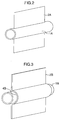
- Figs. 2 and 3 are perspective views showing a partial configuration of a heat transfer tube forming an ice making heat exchanger used for the air conditioner.
- a refrigerating cycle is operated by using midnight electric power mainly at night to store cold heat as ice, and this cold heat is used for air conditioning in the daytime.
- a heat transfer tube 1 in the ice thermal storage tank 5 as an evaporator of refrigerating cycle, a low-temperature, low-pressure cooling medium is caused to flow in a heat exchanger contained in a water tank to make ice on the surface thereof, whereby cold heat is stored.
- the medium passes through a compressor 12, an outdoor heat exchanger 13, which is a condenser, an expansion valve 18A whose opening degree is controlled, the heat transfer tube 1 in the ice thermal storage tank 5, used as an evaporator, and a valve 19, and returns to the compressor 12 through the compressor 12 and the heat exchanger 13.
- the ice generated on the surface has a tube shape whose cross section is substantially circular as shown in Fig. 20, and an unused portion 20 where ice is not made is produced undesirably between the ices 32 generated by the adjacent heat transfer tubes 31 above and below and to the left and right.
- the ice packing factor volume of ice/total water quantity
- ice 32 with a thickness of 60 to 70 mm must be made on the surface of the heat transfer tube 31.
- a thermal resistance from the heat transfer surface to the ice generation surface increases, so that the completion of ice making requires a long period of time.
- the ices 32 growing from the adjacent heat transfer tube 31 confines water in the unused portion 20 so that the water is cut off from escape. Subsequently, therefore, the water in the unused portion 20 freezes and expands, so that there is the possibility of breaking the heat transfer tube 31.
- a plate-shaped ice making heat exchanger is used in the ice thermal storage tank of the ice thermal storage type air conditioner of an internal melt type.
- the heat transfer tube 1 has a pipe shape, and a plate-shaped fin 2 is provided on the heat transfer tube 1.
- the installation direction of the fin 2 is vertical, and a plurality of rows of heat transfer tubes 1 and the fins 2 are arranged.
- an inlet-side header 22 and an outlet-side header 23 are arranged above the ice thermal storage tank 5 so that they are not submerged in the water. Thereby, a heat transfer tube 3 can be inserted from the upper part of the ice thermal storage tank 5, so that the manufacturing property is increased. Since the inlet-side header 22 and an outlet-side header 23 are not submerged in the water, the ice packing factor can be increased. Further, since the confinement of water in the unused portion can be prevented at the time of excessive icing time, the breakage of the heat transfer tube 1 can be avoided.
- the ice packing factor is about 53% when the water level height is 1.21 m.
- the heat transfer tubes 1 provided with a plate-shaped fin 2 in accordance with this embodiment are filled into the ice thermal storage tank of the same size with a pitch of a plurality of rows, that is, a pitch between the plates being 25 mm (10 mm on both surfaces of the plate-shaped fin 2), the ice packing factor can be increased to about 84% with the same water level height.
- the condenser in the ice thermal storage tank 5 has a high pressure, so that the pressure resistance becomes an essential condition.
- the heat transfer tube 1 in accordance with this embodiment has a pipe shape in which the flow path for refrigerant is circular, and has a configuration such that this pipe shape is a skeleton, it is highly pressure-resisting, so that the reliability can be increased even when a non-azeotropic mixture refrigerant, a natural refrigerant, or the like are used.
- the heat transfer tube 1 is used as the ice making heat exchanger for the ice thermal storage type air conditioner, ice is made with a thermal resistance proportional to the thickness of ice, so that the temperature of the refrigerant in the heat transfer tube 1 need not be made low like the conventional ice thermal storage type air conditioner. Therefore, the coefficient of performance (COP) of the refrigerating cycle can be made high, and the electric power consumed before a specified quantity of ice making is reached can be kept low.
- COP coefficient of performance
- the plate-shaped fin 2 can be manufactured easily by pressing or other methods, the heat exchanger is simplified, the manufacture is easy, and the cost can be kept low.
- Fig. 3 is a configuration view showing another embodiment of the heat transfer tube 1A shown in Fig. 2.
- a plate forming the fin 2B is provided with a semicircular concave portion 4B along the outside shape of the heat transfer tube 1B at a location where the plate comes into contact with the tube 1B, by which the heat transfer tube 1B is fixed.
- the contact surface between the heat transfer tube 1B and the fin 2B is increased, so that heat can be transferred more rapidly between the refrigerant flowing in the heat transfer tube 1B and the water (or the ice) outside of the heat transfer tube 1B.
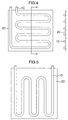
- Figs. 4 and 5 are configuration views showing other embodiments of the heat transfer tube shown in Fig. 2.
- the fin 2C, 2D that is larger than the area occupied by one side of a pipe-shaped heat transfer tube 1C, 1D that lies in the zigzag line on one plane.
- Fig. 4 shows an embodiment of a zigzag tube whose straight pipe portion is horizontal
- Fig. 5 shows an embodiment of a zigzag tube whose straight pipe portion is vertical.
- the fin serves functions of not only increasing the ice making performance but also increasing the rigidity of the heat transfer tube. Therefore, there is no need for providing a support member etc. for the heat transfer tube, so that the structure of heat exchanger can be simplified.
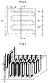
- Fig. 6 is a configuration view showing another embodiment of the heat transfer tube shown in Fig. 4.
- a plate forming the fin 2E is provided with the concave portion 4E along the outside shape of the heat transfer tube 1E at a location where the plate comes into contact with the tube 1E, by which the heat transfer tube 1E is fixed.
- both performances of heat transfer property and rigidity can further be enhanced as compared with the embodiments shown in Figs. 4 and 5.
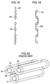
- Fig. 8 is a configuration view showing another embodiment of the heat transfer tube shown in Fig. 6.
- the fin 2F that covers the straight pipe portions excluding bent portions 7 is joined to one side of a heat transfer tube 1F that lies in the zigzag line on one plane. Therefore, when the concave portion 4 shown in Fig. 6, which is provided to join the heat transfer tube 1 to the fin 2F, is formed, the manufacture is made easy because the curved portions are omitted, which is advantageous in further reducing the cost.
- the joint portions for assembling the heat transfer tubes shown in Fig. 10 together are arranged above the water level of the ice thermal storage tank 5. Thereby, troubles caused by improper joining of the joint portions, leakage of the refrigerant in the refrigerating cycle due to corrosion, or entrance of water into the cycle can be prevented, so that the reliability can be increased further.
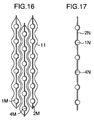
- Fig. 18 is a configuration view showing another embodiment of a method for fixing the fin to the heat transfer tube.
- the heat transfer tubes 1P are arranged more densely at both end portions of plate than at the central portion.
- the cross section of ice 11 easily has a streamline shape such as to be thinner at both ends due to natural convection of surrounding water.
- ice 11 can be made more easily at both ends because cold heat is distributed densely to both end portions of the plate. Therefore, the apparent cross-sectional thickness of the ice 11 can be made uniform, so that the space factor at the local portions at the upper and lower parts of the ice thermal storage tank can be increased.
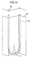
- Fig. 19 is a configuration view showing another embodiment of the heat transfer tube shown in Fig. 2.
- the half peripheral surface of the outside surface of the heat transfer tube 1Q is fixed by the end portion of the plate-shaped fin 2Q from two directions so as to be wrapped.
- the contact area between the heat transfer tube 1Q and the fin 2Q can be increased, and therefore heat is transferred to the fin 2Q more rapidly, so that the ice making time can be shortened when a specified quantity of ice is made.
- the plate-shaped fin is provided, and a plurality of rows of heat transfer tubes and fins are arranged, a space between the heat transfer tubes can be used effectively, so that the ice packing factor can be increased. Also, since the fin is installed vertically, the convection of water in the ice thermal storage tank is accelerated at the time of ice making, so that the breakage of the heat transfer tube can be prevented. Therefore, an ice thermal storage type air conditioner and an ice thermal storage tank can be provided which have improved reliability even when a non-azeotropic mixture refrigerant, a natural refrigerant, or the like is used.
- the heat transfer tube is in a pipe shape of a circular cross section having an outside diameter of 7 to 9 mm, the heat transfer tube is highly pressure-resisting even when a non-azeotropic mixture refrigerant, a natural refrigerant, or the like is used. Since the plate-shaped fins having a thickness of 0.3 to 1.0 mm are laminated at intervals of 10 to 50 mm, an ice thermal storage type air conditioner and an ice thermal storage tank can be provided in which a space in the ice thermal storage tank is used effectively, and thereby the ice packing factor is increased to about 80 to 90%.
Landscapes
- Engineering & Computer Science (AREA)
- Physics & Mathematics (AREA)
- Mechanical Engineering (AREA)
- General Engineering & Computer Science (AREA)
- Thermal Sciences (AREA)
- Geometry (AREA)
- Life Sciences & Earth Sciences (AREA)
- Sustainable Development (AREA)
- Chemical & Material Sciences (AREA)
- Combustion & Propulsion (AREA)
- Compression-Type Refrigeration Machines With Reversible Cycles (AREA)
- Heat-Exchange Devices With Radiators And Conduit Assemblies (AREA)
Applications Claiming Priority (2)
| Application Number | Priority Date | Filing Date | Title |
|---|---|---|---|
| JP10262712A JP2000088297A (ja) | 1998-09-17 | 1998-09-17 | 氷蓄熱式空気調和装置及び氷蓄熱槽 |
| JP26271298 | 1998-09-17 |
Publications (2)
| Publication Number | Publication Date |
|---|---|
| EP0987502A2 true EP0987502A2 (de) | 2000-03-22 |
| EP0987502A3 EP0987502A3 (de) | 2002-06-12 |
Family
ID=17379553
Family Applications (1)
| Application Number | Title | Priority Date | Filing Date |
|---|---|---|---|
| EP99118268A Withdrawn EP0987502A3 (de) | 1998-09-17 | 1999-09-14 | Klimaanlage mit Eisspeicherung und Eisbehälter |
Country Status (3)
| Country | Link |
|---|---|
| US (1) | US6253567B1 (de) |
| EP (1) | EP0987502A3 (de) |
| JP (1) | JP2000088297A (de) |
Cited By (8)
| Publication number | Priority date | Publication date | Assignee | Title |
|---|---|---|---|---|
| WO2008011846A1 (de) * | 2006-07-28 | 2008-01-31 | Webasto Ag | Kälte- und/oder wärmespeicher |
| CN101788172B (zh) * | 2009-01-22 | 2012-07-25 | 珠海格力电器股份有限公司 | 一种蓄能空调机组及其工作方法 |
| GB2489069A (en) * | 2011-03-16 | 2012-09-19 | Green Structures Ltd | Thermal energy store |
| EP2623896A4 (de) * | 2010-09-30 | 2016-03-09 | Panasonic Corp | Wärmespeichervorrichtung und mit dieser wärmespeichervorrichtung ausgestattete klimaanlage |
| WO2018199783A1 (en) * | 2017-04-24 | 2018-11-01 | Mar-Bud Społka Z Ograniczoną Odpowiedzialnością | The device for manufacturing and storing ice |
| TWI658238B (zh) * | 2016-08-12 | 2019-05-01 | 國立勤益科技大學 | 分體式儲能系統及其方法 |
| EP3845851A4 (de) * | 2018-08-27 | 2021-09-01 | Mitsubishi Electric Corporation | Wärmetauscher, wärmetauschereinheit und kältekreislaufvorrichtung |
| PL443031A1 (pl) * | 2022-11-30 | 2024-06-03 | Sre Polska Spółka Z Ograniczoną Odpowiedzialnością | Urządzenie do wytwarzania i magazynowania lodu |
Families Citing this family (38)
| Publication number | Priority date | Publication date | Assignee | Title |
|---|---|---|---|---|
| KR100363969B1 (ko) * | 2000-02-11 | 2002-12-11 | 엘지전자 주식회사 | 냉장고용 증발기 및 헤더 제작 방법 |
| JP2001227793A (ja) * | 2000-02-14 | 2001-08-24 | Hitachi Ltd | 氷蓄熱式熱源装置 |
| JP2002250547A (ja) * | 2000-12-22 | 2002-09-06 | Sekisui Plant Systems Co Ltd | 氷蓄熱装置 |
| US6543245B1 (en) * | 2001-11-08 | 2003-04-08 | Thermo King Corporation | Multi-temperature cold plate refrigeration system |
| AU2003237403A1 (en) * | 2002-06-06 | 2003-12-22 | Nxstage Medical, Inc. | Last-chance quality check and/or air/pyrogen filter for infusion systems |
| US9700663B2 (en) | 2005-01-07 | 2017-07-11 | Nxstage Medical, Inc. | Filtration system for preparation of fluids for medical applications |
| US20080210606A1 (en) | 2004-01-07 | 2008-09-04 | Jeffrey Burbank | Filtration System Preparation of Fluids for Medical Applications |
| ATE434454T1 (de) | 2003-01-07 | 2009-07-15 | Nxstage Medical Inc | Chargenfiltriersystem zur herstellung einer sterilen ersatzflüssigkeit für nierenbehandlungen |
| WO2004091559A2 (en) * | 2003-04-14 | 2004-10-28 | The Procter & Gamble Company | Anhydrous, transfer-resistant cosmetic lip compositions |
| DE602006017654D1 (de) | 2005-01-07 | 2010-12-02 | Nxstage Medical Inc | Filterungssystem zur herstellung von flüssigkeiten für medizinische anwendungen |
| EP1930669B1 (de) * | 2005-09-26 | 2020-07-08 | ETL Corporation | Kühlsystem |
| US7681410B1 (en) | 2006-02-14 | 2010-03-23 | American Power Conversion Corporation | Ice thermal storage |
| JP2007263431A (ja) * | 2006-03-28 | 2007-10-11 | Sanyo Electric Co Ltd | 遷臨界冷凍サイクル装置の製造方法 |
| JP5378203B2 (ja) | 2006-04-07 | 2013-12-25 | ネクステージ メディカル インコーポレイテッド | 医療用の流体を作るろ過システム |
| JP4231518B2 (ja) * | 2006-10-24 | 2009-03-04 | トヨタ自動車株式会社 | 熱交換装置 |
| US7891575B2 (en) * | 2006-11-03 | 2011-02-22 | Sami Samuel M | Method and apparatus for thermal storage using heat pipes |
| US7671567B2 (en) * | 2007-06-15 | 2010-03-02 | Tesla Motors, Inc. | Multi-mode charging system for an electric vehicle |
| US7854131B2 (en) * | 2008-04-16 | 2010-12-21 | The Boeing Company | Thermal buffer system |
| US8146375B2 (en) * | 2009-03-10 | 2012-04-03 | Thermo King Corporation | Hydrocooler with thermal storage |
| US7905110B2 (en) * | 2009-04-02 | 2011-03-15 | Daniel Reich | Thermal energy module |
| US20110079025A1 (en) * | 2009-10-02 | 2011-04-07 | Thermo King Corporation | Thermal storage device with ice thickness detection and control methods |
| US20110100583A1 (en) * | 2009-10-29 | 2011-05-05 | Freund Sebastian W | Reinforced thermal energy storage pressure vessel for an adiabatic compressed air energy storage system |
| US8136368B2 (en) * | 2010-07-19 | 2012-03-20 | Daniel Reich | Modular evaporator and thermal energy storage system for chillers |
| JP2013088049A (ja) * | 2011-10-19 | 2013-05-13 | Mitsubishi Plastics Inc | 潜熱蓄熱槽、及び給湯システム |
| JP2013088050A (ja) * | 2011-10-19 | 2013-05-13 | Mitsubishi Plastics Inc | 潜熱蓄熱槽、及び給湯システム |
| JP6132015B2 (ja) * | 2013-05-17 | 2017-05-24 | 株式会社Ihi | 蓄熱システム |
| KR102236776B1 (ko) * | 2014-09-05 | 2021-04-06 | 삼성전자주식회사 | 증발기, 상기 증발기를 이용하는 냉장 장치 및 상기 냉장 장치의 제어 방법 |
| CN107850327A (zh) * | 2015-03-24 | 2018-03-27 | 艾威普科公司 | 蓄冷冰破断设备 |
| US20160363387A1 (en) * | 2015-06-12 | 2016-12-15 | Hamilton Sundstrand Space Systems International, Inc. | Phase-change material heat exchanger |
| CN106524360A (zh) * | 2016-04-26 | 2017-03-22 | 珠海格力电器股份有限公司 | 冰蓄冷空调系统的控制方法 |
| IL248304B (en) * | 2016-10-10 | 2021-07-29 | Magen Eco Energy A C S Ltd | Heat exchanger and its module |
| JP7001917B2 (ja) * | 2017-03-16 | 2022-01-20 | ダイキン工業株式会社 | 伝熱管ユニットを有する熱交換器 |
| US9989271B1 (en) | 2017-08-14 | 2018-06-05 | Calvin Becker | Air conditioning with thermal storage |
| EP3948138B1 (de) * | 2019-04-05 | 2025-11-12 | Phase Change Energy Solutions, Inc. | Wärmeverwaltungsvorrichtungen und -verfahren |
| WO2021021993A1 (en) * | 2019-08-01 | 2021-02-04 | Weller Ice, LLC | Ice machine for an ice-based thermal storage system |
| GB2601995B (en) * | 2020-12-08 | 2023-09-06 | Dyson Technology Ltd | Heat storage device |
| PL436607A1 (pl) * | 2020-12-31 | 2021-10-25 | Mar-Bud Spółka Z Ograniczoną Odpowiedzialnością Budownictwo Spółka Komandytowa | Układ akumulatora ciepła dla systemów chłodniczych i klimatyzacji |
| US20240337394A1 (en) * | 2023-04-10 | 2024-10-10 | Ice Bear SPV #1, LLC | Integration of a Thermal Energy Storage Unit With An External HVAC System |
Citations (2)
| Publication number | Priority date | Publication date | Assignee | Title |
|---|---|---|---|---|
| JPS6410081A (en) | 1987-06-30 | 1989-01-13 | Nippon Kokan Kk | Cold and hot heat extracting method and device in ice cold accumulator |
| JPH07332711A (ja) | 1994-06-06 | 1995-12-22 | Hitachi Ltd | 氷蓄熱ユニット |
Family Cites Families (14)
| Publication number | Priority date | Publication date | Assignee | Title |
|---|---|---|---|---|
| JPS50153442A (de) * | 1974-05-31 | 1975-12-10 | ||
| US4434843A (en) * | 1978-04-17 | 1984-03-06 | International Environmental Manufacturing Co. | Heat exchanger apparatus |
| JPS55105194A (en) * | 1979-02-07 | 1980-08-12 | Hitachi Ltd | Heat-exchanger |
| FR2529309B1 (fr) * | 1982-06-24 | 1987-07-10 | Comp Generale Electricite | Convecteur eau-air a effet de cheminee pour chauffer un local |
| US5259214A (en) * | 1990-11-08 | 1993-11-09 | Mitsubishi Denki Kabushiki Kaisha | Air conditioning system |
| JPH04356637A (ja) * | 1991-06-03 | 1992-12-10 | Nkk Corp | 氷蓄冷装置における冷熱取出し方法と装置 |
| JPH05157475A (ja) * | 1991-12-11 | 1993-06-22 | Daikin Ind Ltd | 氷蓄熱装置 |
| ES2065808B1 (es) * | 1992-05-06 | 1996-12-16 | Kobol Sa | Intercambiador de calor y su proceso de fabricacion. |
| JP3260418B2 (ja) * | 1992-06-15 | 2002-02-25 | 東京電力株式会社 | 蓄熱式空気調和機 |
| JPH07260212A (ja) * | 1994-03-25 | 1995-10-13 | Daikin Ind Ltd | 氷蓄熱装置 |
| US5649431A (en) * | 1994-11-15 | 1997-07-22 | Tdindustries, Inc. | Thermal storage cooling system |
| US5540276A (en) * | 1995-01-12 | 1996-07-30 | Brazeway, Inc. | Finned tube heat exchanger and method of manufacture |
| JPH08261518A (ja) * | 1995-03-23 | 1996-10-11 | Daikin Ind Ltd | 氷蓄熱装置 |
| US5535820A (en) * | 1995-07-18 | 1996-07-16 | Blissfield Manufacturing Company | Method for assembling a heat exchanger |
-
1998
- 1998-09-17 JP JP10262712A patent/JP2000088297A/ja active Pending
-
1999
- 1999-09-14 EP EP99118268A patent/EP0987502A3/de not_active Withdrawn
- 1999-09-16 US US09/396,878 patent/US6253567B1/en not_active Expired - Fee Related
Patent Citations (2)
| Publication number | Priority date | Publication date | Assignee | Title |
|---|---|---|---|---|
| JPS6410081A (en) | 1987-06-30 | 1989-01-13 | Nippon Kokan Kk | Cold and hot heat extracting method and device in ice cold accumulator |
| JPH07332711A (ja) | 1994-06-06 | 1995-12-22 | Hitachi Ltd | 氷蓄熱ユニット |
Cited By (10)
| Publication number | Priority date | Publication date | Assignee | Title |
|---|---|---|---|---|
| WO2008011846A1 (de) * | 2006-07-28 | 2008-01-31 | Webasto Ag | Kälte- und/oder wärmespeicher |
| CN101788172B (zh) * | 2009-01-22 | 2012-07-25 | 珠海格力电器股份有限公司 | 一种蓄能空调机组及其工作方法 |
| EP2623896A4 (de) * | 2010-09-30 | 2016-03-09 | Panasonic Corp | Wärmespeichervorrichtung und mit dieser wärmespeichervorrichtung ausgestattete klimaanlage |
| GB2489069A (en) * | 2011-03-16 | 2012-09-19 | Green Structures Ltd | Thermal energy store |
| GB2489011A (en) * | 2011-03-16 | 2012-09-19 | Green Structures Ltd | Thermal energy store |
| TWI658238B (zh) * | 2016-08-12 | 2019-05-01 | 國立勤益科技大學 | 分體式儲能系統及其方法 |
| WO2018199783A1 (en) * | 2017-04-24 | 2018-11-01 | Mar-Bud Społka Z Ograniczoną Odpowiedzialnością | The device for manufacturing and storing ice |
| EP3845851A4 (de) * | 2018-08-27 | 2021-09-01 | Mitsubishi Electric Corporation | Wärmetauscher, wärmetauschereinheit und kältekreislaufvorrichtung |
| PL443031A1 (pl) * | 2022-11-30 | 2024-06-03 | Sre Polska Spółka Z Ograniczoną Odpowiedzialnością | Urządzenie do wytwarzania i magazynowania lodu |
| PL247042B1 (pl) * | 2022-11-30 | 2025-04-28 | Sre Polska Spolka Z Ograniczona Odpowiedzialnoscia | Urządzenie do wytwarzania i magazynowania lodu |
Also Published As
| Publication number | Publication date |
|---|---|
| US6253567B1 (en) | 2001-07-03 |
| EP0987502A3 (de) | 2002-06-12 |
| JP2000088297A (ja) | 2000-03-31 |
Similar Documents
| Publication | Publication Date | Title |
|---|---|---|
| US6253567B1 (en) | Ice thermal storage type air conditioner and ice thermal storage tank | |
| KR101137031B1 (ko) | 축냉 열교환기 | |
| US6101821A (en) | Ice thermal storage coil systems and methods | |
| JP5768480B2 (ja) | 蓄冷熱交換器 | |
| CN103930747A (zh) | 板翅管式换热器及具有该板翅管式换热器的制冷空调系统 | |
| JP3353692B2 (ja) | 氷蓄熱式空気調和装置及び氷蓄熱槽 | |
| JPH0345300B2 (de) | ||
| JPH08247678A (ja) | アルミニウム製熱交換器 | |
| JPH0245945B2 (de) | ||
| JP3100074B2 (ja) | 冷却装置 | |
| JPH09318195A (ja) | 積層型蒸発器 | |
| JP2005201625A (ja) | 熱交換器およびその製造方法 | |
| KR101468912B1 (ko) | 가정용 냉장고들 및 냉동고들용 후벽 응축기 | |
| JPH0833287B2 (ja) | 空気調和機用アルミニウム製凝縮器 | |
| JPH0345302B2 (de) | ||
| JPH0345301B2 (de) | ||
| JPH0332944Y2 (de) | ||
| JP2004150710A (ja) | 冷媒蒸発器およびその製造方法 | |
| KR100485140B1 (ko) | 핀튜브를 이용한 빙축기 및 이를 이용한 냉방시스템 | |
| JP2004028470A (ja) | 熱交換器 | |
| CN220398288U (zh) | 一种扁管、扁管组、换热器及空调 | |
| JP4633967B2 (ja) | 氷蓄熱式空気調和装置 | |
| JPH08261518A (ja) | 氷蓄熱装置 | |
| CN109028660A (zh) | 一种翅片式蒸发器及其制作方法 | |
| JPH06137616A (ja) | 氷蓄熱槽用の熱交換コイル |
Legal Events
| Date | Code | Title | Description |
|---|---|---|---|
| PUAI | Public reference made under article 153(3) epc to a published international application that has entered the european phase |
Free format text: ORIGINAL CODE: 0009012 |
|
| 17P | Request for examination filed |
Effective date: 19990914 |
|
| AK | Designated contracting states |
Kind code of ref document: A2 Designated state(s): AT BE CH CY DE DK ES FI FR GB GR IE IT LI LU MC NL PT SE |
|
| AX | Request for extension of the european patent |
Free format text: AL;LT;LV;MK;RO;SI |
|
| PUAL | Search report despatched |
Free format text: ORIGINAL CODE: 0009013 |
|
| AK | Designated contracting states |
Kind code of ref document: A3 Designated state(s): AT BE CH CY DE DK ES FI FR GB GR IE IT LI LU MC NL PT SE |
|
| AX | Request for extension of the european patent |
Free format text: AL;LT;LV;MK;RO;SI |
|
| AKX | Designation fees paid |
Designated state(s): DE FR GB |
|
| STAA | Information on the status of an ep patent application or granted ep patent |
Free format text: STATUS: THE APPLICATION IS DEEMED TO BE WITHDRAWN |
|
| 18D | Application deemed to be withdrawn |
Effective date: 20050401 |