EP0987393B1 - Türband zur schwenkbaren Anbringung eines Türflügels an einem Türrahmen - Google Patents
Türband zur schwenkbaren Anbringung eines Türflügels an einem Türrahmen Download PDFInfo
- Publication number
- EP0987393B1 EP0987393B1 EP99113823A EP99113823A EP0987393B1 EP 0987393 B1 EP0987393 B1 EP 0987393B1 EP 99113823 A EP99113823 A EP 99113823A EP 99113823 A EP99113823 A EP 99113823A EP 0987393 B1 EP0987393 B1 EP 0987393B1
- Authority
- EP
- European Patent Office
- Prior art keywords
- door leaf
- door
- sided
- wing
- hinge
- Prior art date
- Legal status (The legal status is an assumption and is not a legal conclusion. Google has not performed a legal analysis and makes no representation as to the accuracy of the status listed.)
- Expired - Lifetime
Links
- 230000000149 penetrating effect Effects 0.000 claims description 2
- 125000006850 spacer group Chemical group 0.000 description 16
- 230000010354 integration Effects 0.000 description 2
- 230000000052 comparative effect Effects 0.000 description 1
- 230000003993 interaction Effects 0.000 description 1
- 230000035515 penetration Effects 0.000 description 1
- 239000000725 suspension Substances 0.000 description 1
Images

Classifications
-
- E—FIXED CONSTRUCTIONS
- E05—LOCKS; KEYS; WINDOW OR DOOR FITTINGS; SAFES
- E05D—HINGES OR SUSPENSION DEVICES FOR DOORS, WINDOWS OR WINGS
- E05D7/00—Hinges or pivots of special construction
- E05D7/04—Hinges adjustable relative to the wing or the frame
- E05D7/0415—Hinges adjustable relative to the wing or the frame with adjusting drive means
- E05D7/0423—Screw-and-nut mechanisms
-
- E—FIXED CONSTRUCTIONS
- E05—LOCKS; KEYS; WINDOW OR DOOR FITTINGS; SAFES
- E05D—HINGES OR SUSPENSION DEVICES FOR DOORS, WINDOWS OR WINGS
- E05D7/00—Hinges or pivots of special construction
- E05D7/04—Hinges adjustable relative to the wing or the frame
- E05D2007/0476—Pocket hinges
-
- E—FIXED CONSTRUCTIONS
- E05—LOCKS; KEYS; WINDOW OR DOOR FITTINGS; SAFES
- E05D—HINGES OR SUSPENSION DEVICES FOR DOORS, WINDOWS OR WINGS
- E05D7/00—Hinges or pivots of special construction
- E05D7/04—Hinges adjustable relative to the wing or the frame
- E05D2007/0484—Hinges adjustable relative to the wing or the frame in a radial direction
-
- E—FIXED CONSTRUCTIONS
- E05—LOCKS; KEYS; WINDOW OR DOOR FITTINGS; SAFES
- E05Y—INDEXING SCHEME ASSOCIATED WITH SUBCLASSES E05D AND E05F, RELATING TO CONSTRUCTION ELEMENTS, ELECTRIC CONTROL, POWER SUPPLY, POWER SIGNAL OR TRANSMISSION, USER INTERFACES, MOUNTING OR COUPLING, DETAILS, ACCESSORIES, AUXILIARY OPERATIONS NOT OTHERWISE PROVIDED FOR, APPLICATION THEREOF
- E05Y2900/00—Application of doors, windows, wings or fittings thereof
- E05Y2900/10—Application of doors, windows, wings or fittings thereof for buildings or parts thereof
- E05Y2900/13—Type of wing
- E05Y2900/132—Doors
Definitions
- the invention relates to a hinge for pivoting Attaching a door leaf to a door frame according to the generic term of claim 1.
- a door hinge is known from FR 2 434 253 A, which the Suspension of a door wing is used on a furniture body, and in which a door wing-side holding part in the form of a Inlet housing is provided.
- This inlet housing can be fixed in a recess in the door leaf.
- the door hinge also includes a hinged wing part, using a countersunk screw to fix it with a link piece is connectable. In his stuck with the backdrop piece connected state is the joint-side wing part in the vertical direction of the door leaf level and in the thickness direction of the door leaf is firmly held in the inlet housing or on the door leaf.
- the adjustment spindle is actuated by a suitable one Tool on the perpendicular to the door leaf level Leg of the wing part penetrating the door wing End section of the adjusting spindle.
- Both the adjustment spindle and the one to the door leaf level vertical section of the wing part as well as other functional elements the hinge are visible from the outside. Provided a certain adjustment path in the horizontal direction of the door leaf level, where the backdrop piece is from the base of the inlet housing is moved away, exceeded, is even the scenery piece is visible from the outside.
- the invention is based, a door hinge the task to create the type described above, which on the one hand is structurally and technically simple and on the other hand the overall aesthetic and aesthetic impression of a door little affected.
- the leg on the door wing side that is perpendicular to the door wing plane of the wing part allows adjustment of the wing part also from the narrow side of the door wing.
- Door hinge in the door is the design according to claim 2 advantageous.
- Exact guidance of the movable wing part is according to claim 4 reachable. This creates an exact fixation of the wing part in the thickness direction of the door wing and in Vertical direction of the door leaf level reached, the adjustability of the wing part in the horizontal direction of the door wing level is not affected.
- Door hinge on the door leaf is the design according to Claim 5 useful.
- the arrangement provided according to claim 10 is expedient the guide pin and according to claim 11 intended arrangement of the adjusting spindle.
- the preferably cylindrical guide pin or the preferably round guide hole according to Claim 15 arranged.
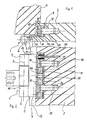
- FIG. 1 and 2 in a horizontal or vertical Sectional view shown door hinge according to the invention 1 serves one in Figures 1 and 2 only partially Door leaf 2 shown about a pivot axis 3rd pivotable on a only shown in Figure 1 Store door frame 4.
- the door hinge 1 has a wing part 5, which into a hinge section 6, one to the level of the door leaf parallel joint-side leg 7 and one to the joint-side Leg 7 bent at right angles and thus to The door leaf level is divided into vertical legs 8 on the door leaf side.
- the joint section 6 forms two cylindrical sleeves 9, 10 with which the wing part 5 pivotable about the pivot axis 3 is stored. About tangent to the cylindrical sleeves 9, 10 extends the joint side Leg 7 of the wing part 5 into one formed in the door wing 2 Recess 11.
- the leg 8 on the door wing side of the wing part 5 bends 90 degrees from the joint-side leg 7 of the wing part 5.
- This recess 15 has the shape of a Slot and corresponds in terms of their vertical Extent and in terms of their width of the vertical extent and the thickness of the articulated leg 7 of the Wing part 5.
- the door wing-side holding part 20 On its base side of the recess 11 of the door leaf 2 facing away from the outer surface, the door wing-side holding part 20 four spacer sleeves 25, 26, 27, 28, which are suitable Are attached to the door leaf-side holding part 20 and in the direction of the opening surface of the recess 11 of the Door leaf 2 extend.
- the spacer sleeves 25, 26, 27, 28 are in the door wing side Leg 8 of the wing part 5 formed openings 29, 30, 31, 32 assigned which the spacer sleeves 25, 26, 27, 28 surrounded form-fitting. This makes it moveable of the wing side leg 8 and thus the wing part 5 given within the recess 11 in the door leaf 2, where the only direction of movement is a movement in the horizontal direction the door leaf level is possible. A movement in the vertical direction of the door leaf level or in the thickness direction of the door leaf 2 is due to the interaction of the spacers 25, 26, 27, 28 and the openings 29, 30, 31, 32 and the guide pin 18, 19 and the guide holes 21, 22 or the guide bores 23, 24 prevented.
- the cover plate 17 has four holes 33, 34, 35, 36, those formed in the spacer sleeves 25, 26, 27, 28 Bores 37, 38, 39, 40 and with in the door part holding part 20 holes 41, 42, 43, 44 are aligned.
- the holes 33, 34, 35, 36 on the cover plate side, the spacer sleeve-side Bores 37, 38, 39, 40 and the holding part side Holes 41, 42, 43, 44 are made by four screws 45 interspersed so that the cover plate 17 and the door wing side Holding part 20 in compliance with the distance sleeves 25, 26, 27, 28 predetermined distance between can be firmly attached to them in the recess 11 of the door leaf 2 are.
- the relative movement of the door leaf 2 with respect to the door leaf side Leg 8 of the wing part 5 and thus in relation on the door frame 4 in the horizontal direction of the door leaf level is accomplished by means of an adjusting spindle 46 which between a cover opening 47 and a fixing opening 48 on the holding part side in its axial direction fixed and rotatable between the cover plate 17 and the door wing-side holding part 20 is held.
- the adjusting spindle 46 has an external thread section 49, with which they have a corresponding in the door wing leg 8th of the wing part 5 formed through threaded bore 50.
- the adjusting spindle 46 has one from the front the cover plate 17 actuated polygonal bore 51; at Rotation of the adjusting spindle 46 moves in one direction Door wing with respect to the pivot axis 3 in one a rotation of the adjusting spindle 46 in the opposite The door wing 2 moves in relation to the pivot axis 3 in the opposite direction.
- Opening 30 is by means of how, in particular 3 shows screw connection 52 of the guide bolts 18 on the base of the recess 11 of the Door wing 2 facing outer surface attached.
- the lower by means of a similar screw connection 53 Guide pin 19 between the lower opening 32 and the opening 31 arranged above it on the door wing side Leg 8 of the wing part 5 arranged.
- the fixing opening 47 is formed, which with the holding part Fixing opening 48 is aligned.
- the diameter the cover plate-side fixing opening 47 corresponds to that a section 54 of the polygonal bore 51 adjusting spindle 46 shown in FIG. 10; the diameter the fixing opening 48 on the holding part side corresponds to that an end section 55 of the adjusting spindle on the right in FIG. 10 46th
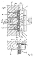
- the upper adjusting spindle 46a in FIG. 11 in the vertical direction and the fixing openings 47a, 48a assigned to it are at this embodiment between the top 25 and the one thereon following spacer sleeve 26 arranged.
- Embodiment cylindrical guide pin 60 From the outer surface facing the wing part holding part 20 of the door wing side perpendicular to the door wing level Leg 8 of the wing part 5 is shown in Embodiment cylindrical guide pin 60 before a formed in the door wing-side holding part 20, shown in Embodiment round guide hole 61 through and in a guide bore 62 formed in the door leaf 2 intervenes.
- the cylindrical guide pin 60 and the round guide hole 61 is approximately in the vertical direction at the center of the door leaf level vertical leg 8 side of the wing part 5 or the door wing-side holding part 20 is arranged.
Landscapes
- Engineering & Computer Science (AREA)
- Mechanical Engineering (AREA)
- Hinges (AREA)
Description
- Figur 1
- eine horizontale Schnittdarstellung des erfindungsgemäßen Türbandes im montierten Zustand;
- Figur 2
- eine vertikale Schnittdarstellung des in Figur 1 dargestellten Türbandes;
- Figur 3
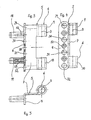
- eine teilweise geschnittene Seitenansicht eines Flügelteils des in den Figuren 1 und 2 dargestellten erfindungsgemäßen Türbandes;
- Figur 4
- eine teilweise geschnittene Vorderansicht des in Figur 3 dargestellten Flügelteils;
- Figur 5
- eine Draufsicht auf das in den Figuren 3 und 4 dargestellte Flügelteil;
- Figur 6
- eine Seitenansicht auf ein Halteteil des in den Figuren 1 und 2 dargestellten erfindungsgemäßen Türbandes;
- Figur 7
- eine Vorderansicht des in Figur 6 dargestellten Halteteils;
- Figur 8
- eine Vorderansicht einer Abdeckplatte des in den Figuren 1 und 2 dargestellten erfindungsgemäßen Türbandes;
- Figur 9
- eine Seitenansicht einer Abstandshülse des in den Figuren 1 und 2 dargestellten erfindungsgemäßen Türbandes;
- Figur 10
- eine Seitenansicht einer Verstellspindel des in den Figuren 1 und 2 dargestellten erfindungsgemäßen Türbandes;
- Figur 11
- eine vertikale Schnittdarstellung einer weiteren Ausführungsform des erfindungsgemäßen Türbandes; und
- Figur 12
- eine horizontale Schnittdarstellung des in Figur 11 dargestellten Türbandes im montierten Zustand.
Claims (15)
- Türband zur schwenkbaren Anbringung eines Türflügels (2) an einem Türrahmen (4), mit einem türflügelseitigen Halteteil (20), das am Türflügel (2) fest anbringbar ist, und einem gelenkseitigen Flügelteil (5), das in Horizontalrichtung der Türflügelebene mittels einer Stellspindel (46) verstellbar und in Vertikalrichtung der Türflügelebene und in Dickenrichtung des Türflügels (2) fest am türflügelseitigen Halteteil (20) bzw. am Türflügel (2) fixiert ist und das einen zur Türflügelebene parallelen gelenkseitigen Schenkel (7) und einen zur Türflügelebene senkrechten türflügelseitigen Schenkel (8) aufweist, dadurch gekennzeichnet, dass der zur Türflügelebene parallele gelenkseitigen Schenkel (7) des Flügelteils (5) eine längliche Aussparung (15) einer senkrecht zur Türflügelebene auf der gelenkseitigen Schmalseite des Türflügels (2) befestigbaren, dem türflügelseitigen Halteteil (20) zugeordneten Abdeckplatte (17) durchdringt und dass in der Abdeckplatte (17) und im türflügelseitigen Halteteil (20) jeweils eine Fixieröffnung (47; 48) ausgebildet ist, in denen in ihrer Axialrichtung fixiert und drehbar die Stellspindel (46) gehaltert ist, deren Außengewindeabschnitt (49) in Gewindeeingriff mit einer im zur Türflügelebene senkrechten türflügelseitigen Schenkel (8) des Flügelteils (5) ausgebildeten Gewindebohrung (50) steht.
- Türband nach Anspruch 1, bei dem die längliche Aussparung (15) der Abdeckplatte (17) an der einem Türanschlag (12) zugewandten Längsseite der Abdeckplatte (17) vorgesehen ist.
- Türband nach Anspruch 2, bei dem die aussparungsseitige Kante (16) der Abdeckplatte (17) mit der dieser zugewandten Außenfläche (13) des Türanschlags (12) fluchtet und in dieser Außenfläche (13) des Türanschlags (12) eine Ausnehmung (14) ausgebildet ist, deren Tiefe der Dicke des zur Türflügelebene parallelen gelenkseitigen Schenkels (7) des Flügelteils (5) entspricht.
- Türband nach einem der Ansprüche 1 bis 3, bei dem zwischen dem türflügelseitigen Halteteil (20) und der ihm zugeordneten Abdeckplatte (17) sich in Horizontalrichtung der Türflügelebene erstreckende, vorzugsweise zylindrische Abstandshülsen (25, 26, 27, 28) angeordnet sind, die vorzugsweise runde Durchbrechungen (29, 30, 31, 32) im zur Türflügelebene senkrechten Schenkel (8) des Flügelteils (5) formschlüssig durchgreifen.
- Türband nach Anspruch 4, dessen Abstandshülsen (25, 26, 27, 28) mittige Bohrungen (37, 38, 39, 40) aufweisen, denen Löcher (33, 34, 35, 36; 41, 42, 43, 44) der Abdeckplatte (17) und des türflügelseitigen Halteteils (20) zugeordnet sind, wobei die Abdeckplatte (17), die Abstandshülsen (25, 26, 27, 28) und das türflügelseitige Halteteil (20) mittels die abdeckplatten- und halteteilseitigen Löcher (33, 34, 35, 36; 41, 42, 43, 44) und die abstandshülsenseitigen Bohrungen (37, 38, 39, 40) durchgreifenden Schrauben (45) im Flügelteil (2) verschraubbar sind.
- Türband nach Anspruch 4 oder 5, dessen Abstandshülsen (25, 26, 27, 28) am türflügelseitigen Halteteil (20) befestigt sind.
- Türband nach einem der Ansprüche 4 bis 6, bei dem vier Abstandshülsen (25, 26, 27, 28) vorgesehen sind.
- Türband nach einem der Ansprüche 1 bis 7, bei dem von der dem türflügelseitigen Halteteil (20) zugewandten Außenfläche des zur Türflügelebene senkrechten türflügelseitigen Schenkels (8) des Flügelteils (5) vorzugsweise zylindrische Führungsbolzen (18, 19) vorstehen, die im türflügelseitigen Halteteil (20) ausgebildete, vorzugsweise runde Führungslöcher (21, 22) durch- und in im Türflügel (2) ausbildbare Führungsbohrungen (23, 24) eingreifen.
- Türband nach Anspruch 8, bei dem zwei Führungsbolzen (18, 19) vorgesehen sind.
- Türband nach Anspruch 9, bei dem der in Vertikalrichtung obere Führungsbolzen (18) zwischen der oberen (25) und der darauf folgenden Abstandshülse (26) und der in Vertikalrichtung untere Führungsbolzen (19) zwischen der unteren (28) und der über dieser angeordneten Abstandshülse (27) angeordnet ist.
- Türband nach einem der Ansprüche 1 bis 10, bei dem die Stellspindel (46) und die diese halternden Fixieröffnungen (47, 48) in Vertikalrichtung etwa mittig der Abdeckplatte (17) und des türflügelseitigen Halteteils (20) angeordnet sind.
- Türband nach einem der Ansprüche 1 bis 7, mit zwei Stellspindeln (46a, 46b), von denen jede in ihrer Axialrichtung fixiert und drehbar zwischen einer abdeckplattenseitigen (47a bzw. 47b) und einer halteteilseitigen Fixieröffnung (48a bzw. 48b) gehaltert ist und mit einem Außengewindeabschnitt (49a bzw. 49b) in Gewindeeingriff mit einer im zur Türflügelebene senkrechten türflügelseitigen Schenkel (8) des Flügelteils (5) ausgebildeten Gewindebohrung (50a bzw. 50b) steht.
- Türband nach Anspruch 12, bei dem die in Vertikalrichtung obere Stellspindel (46a) und die ihr zugeordneten Fixieröffnungen (47a, 48a) zwischen der oberen (25) und der darauf folgenden Abstandshülse (26) und die in Vertikalrichtung untere Stellspindel (46b) und die ihr zugeordneten Fixieröffnungen (47b, 48b) zwischen der unteren (28) und der über dieser angeordneten Abstandshülse (27) angeordnet ist.
- Türband nach Anspruch 12 oder 13, bei dem von der dem türflügelseitigen Halteteil (20) zugewandten Außenfläche des zur Türflügelebene senkrechten türflügelseitigen Schenkels (8) des Flügelteils (5) ein vorzugsweise zylindrischer Führungsbolzen (60) vorsteht, der ein im türflügelseitigen Halteteil (20) ausgebildetes, vorzugsweise rundes Führungsloch (61) durch- und in eine im Türflügel (2) ausbildbare Führungsbohrung (62) eingreift.
- Türband nach Anspruch 14, bei dem der vorzugsweise zylindrische Führungsbolzen (60) bzw. das vorzugsweise runde Führungsloch (61) in Vertikalrichtung etwa mittig des zur Türflügelebene senkrechten türflügelseitigen Schenkels (8) des Flügelteils (5) bzw. des türflügelseitigen Halteteils (20) angeordnet ist.
Applications Claiming Priority (2)
| Application Number | Priority Date | Filing Date | Title |
|---|---|---|---|
| DE19842769A DE19842769C2 (de) | 1998-01-21 | 1998-09-18 | Türband zur schwenkbaren Anbringung eines Türflügels an einem Türrahmen |
| DE19842769 | 1998-09-18 |
Publications (3)
| Publication Number | Publication Date |
|---|---|
| EP0987393A2 EP0987393A2 (de) | 2000-03-22 |
| EP0987393A3 EP0987393A3 (de) | 2001-02-28 |
| EP0987393B1 true EP0987393B1 (de) | 2004-10-27 |
Family
ID=7881385
Family Applications (1)
| Application Number | Title | Priority Date | Filing Date |
|---|---|---|---|
| EP99113823A Expired - Lifetime EP0987393B1 (de) | 1998-09-18 | 1999-07-15 | Türband zur schwenkbaren Anbringung eines Türflügels an einem Türrahmen |
Country Status (2)
| Country | Link |
|---|---|
| EP (1) | EP0987393B1 (de) |
| AT (1) | ATE280880T1 (de) |
Families Citing this family (2)
| Publication number | Priority date | Publication date | Assignee | Title |
|---|---|---|---|---|
| DE10152366C5 (de) * | 2001-10-24 | 2004-12-02 | Simonswerk, Gmbh | Aufnahmevorrichtung zur in Türdicken- oder Türquerrichtung verstellbaren Halterung eines Bandlappens einer Türflügelschwenkhalterung an einem Hohlprofil, z.B. einem Aluminiumprofil |
| US6721992B2 (en) | 2002-06-19 | 2004-04-20 | Oren Cotton | Boat hinge cover |
Family Cites Families (2)
| Publication number | Priority date | Publication date | Assignee | Title |
|---|---|---|---|---|
| DE7825189U1 (de) * | 1978-08-24 | 1978-11-30 | Oni-Metallwarenfabriken Guenter & Co, 4973 Vlotho | Verstellbares tuerband |
| NO304158B1 (no) * | 1996-11-21 | 1998-11-02 | Grorud Ind As | Anordning ved en d°rhengselkonstruksjon av innsneppingstypen |
-
1999
- 1999-07-15 EP EP99113823A patent/EP0987393B1/de not_active Expired - Lifetime
- 1999-07-15 AT AT99113823T patent/ATE280880T1/de not_active IP Right Cessation
Also Published As
| Publication number | Publication date |
|---|---|
| EP0987393A3 (de) | 2001-02-28 |
| EP0987393A2 (de) | 2000-03-22 |
| ATE280880T1 (de) | 2004-11-15 |
Similar Documents
| Publication | Publication Date | Title |
|---|---|---|
| DE3502175C2 (de) | ||
| AT391344B (de) | Scharnier | |
| DE2514357C3 (de) | Beschlag zum verschwenkbaren Verbinden einer Möbelplatte mit einem feststehenden Möbelteil | |
| EP0279337A1 (de) | Duschabtrennung mit einem Drehflügel | |
| DE19833708A1 (de) | Höhenverstellbares Hängesystem mit Diebstahlsicherung | |
| EP2297418B1 (de) | Scharnier | |
| AT6964U1 (de) | Scharnier | |
| DE19947670A1 (de) | Drehband für Türen oder Fenster | |
| DE10110311C2 (de) | Scharnier mit Höhenverstellschraube | |
| EP1017920B1 (de) | Beschlag zur drehlagerung eines fenster- oder türflügels | |
| DE102013100305B3 (de) | Band, insbesondere für Kunststoff-Türen und -Fenster | |
| AT401548B (de) | Rahmenscharnier | |
| DE3022440C2 (de) | Mehrteilige Grundplatte für Möbelscharniere | |
| DE3522670A1 (de) | Band fuer tueren, fenster und dergleichen | |
| EP0215281A2 (de) | Flügellager für ein Fenster, eine Tür od. dgl. | |
| DE19842769C2 (de) | Türband zur schwenkbaren Anbringung eines Türflügels an einem Türrahmen | |
| EP0487825B1 (de) | Verdeckt angeordneter Beschlag für Drehflügel, insb. für Dreh-Kipp-Flügel von Fenstern oder Türen | |
| DE1759642C3 (de) | Mehrfach verstellbares Scharnier | |
| DE19649071A1 (de) | Beschlag zum Befestigen eines Türflügels, insbesondere eines Türflügels einer Duschabtrennung aus Glas, Kunststoff oder dergleichen | |
| DE3001070A1 (de) | Eckgelenk fuer drehkippfenster, -tueren o.dgl. | |
| CH681485A5 (de) | ||
| EP0987393A2 (de) | Türband zur schwenkbaren Anbringung eines Türflügels an einem Türrahmen | |
| EP1106763B1 (de) | Band für Türen, Fenster oder dergleichen | |
| EP1512817B1 (de) | Band für Türen, Fenster oder dergleichen | |
| EP1560996A1 (de) | Beschlaganordnung für glastüren |
Legal Events
| Date | Code | Title | Description |
|---|---|---|---|
| PUAI | Public reference made under article 153(3) epc to a published international application that has entered the european phase |
Free format text: ORIGINAL CODE: 0009012 |
|
| AK | Designated contracting states |
Kind code of ref document: A2 Designated state(s): AT BE CH CY DE DK ES FI FR GB GR IE IT LI LU MC NL PT SE |
|
| AX | Request for extension of the european patent |
Free format text: AL;LT;LV;MK;RO;SI |
|
| PUAL | Search report despatched |
Free format text: ORIGINAL CODE: 0009013 |
|
| AK | Designated contracting states |
Kind code of ref document: A3 Designated state(s): AT BE CH CY DE DK ES FI FR GB GR IE IT LI LU MC NL PT SE |
|
| AX | Request for extension of the european patent |
Free format text: AL;LT;LV;MK;RO;SI |
|
| 17P | Request for examination filed |
Effective date: 20010802 |
|
| AKX | Designation fees paid |
Free format text: AT BE CH CY DE DK ES FI FR GB GR IE IT LI LU MC NL PT SE |
|
| 17Q | First examination report despatched |
Effective date: 20030213 |
|
| GRAP | Despatch of communication of intention to grant a patent |
Free format text: ORIGINAL CODE: EPIDOSNIGR1 |
|
| GRAS | Grant fee paid |
Free format text: ORIGINAL CODE: EPIDOSNIGR3 |
|
| GRAA | (expected) grant |
Free format text: ORIGINAL CODE: 0009210 |
|
| AK | Designated contracting states |
Kind code of ref document: B1 Designated state(s): AT BE CH CY DE DK ES FI FR GB GR IE IT LI LU MC NL PT SE |
|
| PG25 | Lapsed in a contracting state [announced via postgrant information from national office to epo] |
Ref country code: NL Free format text: LAPSE BECAUSE OF FAILURE TO SUBMIT A TRANSLATION OF THE DESCRIPTION OR TO PAY THE FEE WITHIN THE PRESCRIBED TIME-LIMIT Effective date: 20041027 Ref country code: IT Free format text: LAPSE BECAUSE OF FAILURE TO SUBMIT A TRANSLATION OF THE DESCRIPTION OR TO PAY THE FEE WITHIN THE PRESCRIBED TIME-LIMIT;WARNING: LAPSES OF ITALIAN PATENTS WITH EFFECTIVE DATE BEFORE 2007 MAY HAVE OCCURRED AT ANY TIME BEFORE 2007. THE CORRECT EFFECTIVE DATE MAY BE DIFFERENT FROM THE ONE RECORDED. Effective date: 20041027 Ref country code: IE Free format text: LAPSE BECAUSE OF FAILURE TO SUBMIT A TRANSLATION OF THE DESCRIPTION OR TO PAY THE FEE WITHIN THE PRESCRIBED TIME-LIMIT Effective date: 20041027 Ref country code: GB Free format text: LAPSE BECAUSE OF FAILURE TO SUBMIT A TRANSLATION OF THE DESCRIPTION OR TO PAY THE FEE WITHIN THE PRESCRIBED TIME-LIMIT Effective date: 20041027 Ref country code: FR Free format text: LAPSE BECAUSE OF FAILURE TO SUBMIT A TRANSLATION OF THE DESCRIPTION OR TO PAY THE FEE WITHIN THE PRESCRIBED TIME-LIMIT Effective date: 20041027 Ref country code: FI Free format text: LAPSE BECAUSE OF FAILURE TO SUBMIT A TRANSLATION OF THE DESCRIPTION OR TO PAY THE FEE WITHIN THE PRESCRIBED TIME-LIMIT Effective date: 20041027 |
|
| REG | Reference to a national code |
Ref country code: GB Ref legal event code: FG4D Free format text: NOT ENGLISH |
|
| REG | Reference to a national code |
Ref country code: CH Ref legal event code: EP |
|
| REG | Reference to a national code |
Ref country code: IE Ref legal event code: FG4D Free format text: GERMAN |
|
| REF | Corresponds to: |
Ref document number: 59910937 Country of ref document: DE Date of ref document: 20041202 Kind code of ref document: P |
|
| PG25 | Lapsed in a contracting state [announced via postgrant information from national office to epo] |
Ref country code: SE Free format text: LAPSE BECAUSE OF FAILURE TO SUBMIT A TRANSLATION OF THE DESCRIPTION OR TO PAY THE FEE WITHIN THE PRESCRIBED TIME-LIMIT Effective date: 20050127 Ref country code: GR Free format text: LAPSE BECAUSE OF FAILURE TO SUBMIT A TRANSLATION OF THE DESCRIPTION OR TO PAY THE FEE WITHIN THE PRESCRIBED TIME-LIMIT Effective date: 20050127 Ref country code: DK Free format text: LAPSE BECAUSE OF FAILURE TO SUBMIT A TRANSLATION OF THE DESCRIPTION OR TO PAY THE FEE WITHIN THE PRESCRIBED TIME-LIMIT Effective date: 20050127 |
|
| PG25 | Lapsed in a contracting state [announced via postgrant information from national office to epo] |
Ref country code: ES Free format text: LAPSE BECAUSE OF FAILURE TO SUBMIT A TRANSLATION OF THE DESCRIPTION OR TO PAY THE FEE WITHIN THE PRESCRIBED TIME-LIMIT Effective date: 20050207 |
|
| NLV1 | Nl: lapsed or annulled due to failure to fulfill the requirements of art. 29p and 29m of the patents act | ||
| REG | Reference to a national code |
Ref country code: IE Ref legal event code: FD4D |
|
| GBV | Gb: ep patent (uk) treated as always having been void in accordance with gb section 77(7)/1977 [no translation filed] |
Effective date: 20041027 |
|
| PG25 | Lapsed in a contracting state [announced via postgrant information from national office to epo] |
Ref country code: LU Free format text: LAPSE BECAUSE OF NON-PAYMENT OF DUE FEES Effective date: 20050715 Ref country code: CY Free format text: LAPSE BECAUSE OF FAILURE TO SUBMIT A TRANSLATION OF THE DESCRIPTION OR TO PAY THE FEE WITHIN THE PRESCRIBED TIME-LIMIT Effective date: 20050715 Ref country code: AT Free format text: LAPSE BECAUSE OF NON-PAYMENT OF DUE FEES Effective date: 20050715 |
|
| PG25 | Lapsed in a contracting state [announced via postgrant information from national office to epo] |
Ref country code: MC Free format text: LAPSE BECAUSE OF NON-PAYMENT OF DUE FEES Effective date: 20050731 Ref country code: LI Free format text: LAPSE BECAUSE OF NON-PAYMENT OF DUE FEES Effective date: 20050731 Ref country code: CH Free format text: LAPSE BECAUSE OF NON-PAYMENT OF DUE FEES Effective date: 20050731 Ref country code: BE Free format text: LAPSE BECAUSE OF NON-PAYMENT OF DUE FEES Effective date: 20050731 |
|
| PLBE | No opposition filed within time limit |
Free format text: ORIGINAL CODE: 0009261 |
|
| STAA | Information on the status of an ep patent application or granted ep patent |
Free format text: STATUS: NO OPPOSITION FILED WITHIN TIME LIMIT |
|
| 26N | No opposition filed |
Effective date: 20050728 |
|
| EN | Fr: translation not filed | ||
| REG | Reference to a national code |
Ref country code: CH Ref legal event code: PL |
|
| BERE | Be: lapsed |
Owner name: *SIMONSWERK G.M.B.H. Effective date: 20050731 |
|
| PG25 | Lapsed in a contracting state [announced via postgrant information from national office to epo] |
Ref country code: PT Free format text: LAPSE BECAUSE OF NON-PAYMENT OF DUE FEES Effective date: 20050327 |
|
| PGFP | Annual fee paid to national office [announced via postgrant information from national office to epo] |
Ref country code: DE Payment date: 20090918 Year of fee payment: 11 |
|
| PG25 | Lapsed in a contracting state [announced via postgrant information from national office to epo] |
Ref country code: DE Free format text: LAPSE BECAUSE OF NON-PAYMENT OF DUE FEES Effective date: 20110201 |
|
| REG | Reference to a national code |
Ref country code: DE Ref legal event code: R119 Ref document number: 59910937 Country of ref document: DE Effective date: 20110201 |