EP0984623A2 - Einrichtung mit einer eingeschränkten Anzahl von Mikroprozessoren und Verfahren für ein Gerätansteuerungssystem unter Verwendung einer impedanzisolierenden Expansionsschaltung - Google Patents
Einrichtung mit einer eingeschränkten Anzahl von Mikroprozessoren und Verfahren für ein Gerätansteuerungssystem unter Verwendung einer impedanzisolierenden Expansionsschaltung Download PDFInfo
- Publication number
- EP0984623A2 EP0984623A2 EP99306960A EP99306960A EP0984623A2 EP 0984623 A2 EP0984623 A2 EP 0984623A2 EP 99306960 A EP99306960 A EP 99306960A EP 99306960 A EP99306960 A EP 99306960A EP 0984623 A2 EP0984623 A2 EP 0984623A2
- Authority
- EP
- European Patent Office
- Prior art keywords
- bus
- expansion circuit
- single main
- main system
- components
- Prior art date
- Legal status (The legal status is an assumption and is not a legal conclusion. Google has not performed a legal analysis and makes no representation as to the accuracy of the status listed.)
- Ceased
Links
Images


Classifications
-
- G—PHYSICS
- G06—COMPUTING; CALCULATING OR COUNTING
- G06F—ELECTRIC DIGITAL DATA PROCESSING
- G06F13/00—Interconnection of, or transfer of information or other signals between, memories, input/output devices or central processing units
- G06F13/38—Information transfer, e.g. on bus
- G06F13/40—Bus structure
- G06F13/4063—Device-to-bus coupling
- G06F13/4068—Electrical coupling
-
- G—PHYSICS
- G06—COMPUTING; CALCULATING OR COUNTING
- G06F—ELECTRIC DIGITAL DATA PROCESSING
- G06F13/00—Interconnection of, or transfer of information or other signals between, memories, input/output devices or central processing units
- G06F13/38—Information transfer, e.g. on bus
Definitions
- This invention relates to reduced microprocessor apparatus and methods for device control system using impedance isolating expansion circuit.
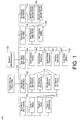
- HDTV system 100 includes a system processor 102 which is coupled to and which controls five separate sub-microprocessors sub micro 104, sub micro 106, sub micro 108, sub micro 110, and sub micro 112.
- Each of the five sub micros 104, 106, 108, 110 and 112 controls numerous other HDTV components.
- sub micro 104 controls tuner operation including tuner components 114.
- sub micro 106 controls HDTV monitor deflection operation via components 116.
- Sub micro 108 controls on-screen display (OSD) functions with OSD device 118.
- sub micro 110 controls multi-image drivers (MID) with components 120.
- sub micro 112 controls MUSE (Japanese HDTV standard) functions with components 122. It will also be seen from Japanese HDTV standard.
- the conventional multi-processor architecture of Figure 1 has several disadvantages associated therewith. Such disadvantages include, for example, substantial design complexity and increased costs resulting from the use of multiple microprocessors. Thus, some attempt has been made to design a consumer electronics product (e.g. a TV, an HDTV, a DVD, and the like) using only a single controlling microprocessor. Such a single microprocessor-controlled system not only reduces the system complexity and cost, but also increases the integration of system control functions.
- prior art single microprocessor-controlled systems often demand a powerful system microprocessor with a very strong driving capability. The requirement for a microprocessor with a very strong driving capability necessitates the use of a more powerful, and correspondingly more expensive, microprocessor. Thus, some prior art single microprocessor-controlled systems may be nearly as expensive as conventional systems having multiple microprocessors.
- Embodiments of the present invention provide a method and apparatus having a reduced number of system microprocessors in a device. Additionally, embodiments of the present invention provides a method and apparatus which achieves the above-listed accomplishment and wherein the device does not impose prohibitively high driving requirements on the system microprocessor. Embodiments of the present invention further provide a method and apparatus which achieves both of the above-listed accomplishments and wherein the device does not suffer from severe signal distortion.
- the present invention includes a single main system microprocessor.
- This embodiment further includes an impedance isolating expansion circuit.
- the single main system microprocessor and the impedance isolating expansion circuit are coupled together using a bus.
- a plurality of components are coupled to the impedance isolating expansion circuit such that the plurality of components are not directly connected to the bus and such that the plurality of components do not induce a direct impedance load on the bus.
- the present invention allows the single main system microprocessor to operate effectively and without severe signal distortion.
- the bus has a plurality of second components coupled thereto.
- the present invention includes the features of the above-described embodiment and further recites that the bus used to couple the single main system microprocessor to the impedance isolating expansion circuit is an I 2 C bus.
- the bus used to couple the single main system microprocessor to the impedance isolating expansion circuit is an I 2 C bus.
- other embodiments include the aforementioned features and recite that the first components are coupled to the impedance isolating expansion circuit using an I 2 C bus.
- HDTV system 200 includes a single main system microprocessor 202. That is, unlike conventional devices (see e.g. Figure 1), the present embodiment has only one main system microprocessor for controlling the operation of HDTV system 200.
- system 200 of the present embodiment further includes an impedance isolating expansion circuit 204.
- Impedance isolating expansion circuit 204 is coupled to single main system microprocessor 202 by a bus 206. As shown in Figure 2, numerous components are coupled to impedance isolating expansion circuit 204. In the present embodiment.
- a bus 205 is used to couple impedance isolating expansion circuit to the aforementioned numerous components.
- the numerous components include, for example: analog tuners 208; audio switches 210; video switch 212; 3D-com filter 214; auto wide main 216; chroma decoders 218 and 220; MID devices 222, 224, 226, 228, and 230; digital deflection controller 232; digital-to-analog converters 234; and dynamic convergence components 236 and 238.
- the numerous aforementioned components are not directly connected to bus 206. That is, unlike prior art architectures, in the present invention, impedance isolating expansion circuit 204 eliminates the direct connection of multiple components to the bus to which main system microprocessor 202 is coupled.
- impedance isolating expansion circuit 204 prevents numerous components 208-238 from inducing a direct impedance load on bus 206.
- single main system microprocessor 202 of the present embodiment does not have a prohibitively high driving requirement placed thereon.
- impedance isolating expansion circuit 204 prevents numerous components 208-238 from inducing a direct impedance load on bus 206, and impedance isolating expansion circuit eliminates the need for a more powerful, and correspondingly more expensive, single main system microprocessor 202.
- specific components, 208-238 are recited in the present embodiment, the present invention is well suited to having various other quantities and/or types of components coupled to impedance isolating expansion circuit 204.
- additional components 240, 242, and 244 are coupled directly to bus 206. Additional components 246 and 248 are also coupled to single main system microprocessor 202 in this embodiment. Although directly coupled to bus 206, components 240-244 do not induce a significant impedance load on bus 206. Thus, the embodiment of Figure 2 does not necessitate the use of a more powerful, and correspondingly more expensive, microprocessor.
- bus 206 is an I 2 C bus.
- bus 205 is an I 2 C bus.
- impedance isolating expansion circuit 204 is an I 2 C bus IC chip circuit such as, for example, I 2 C bus IC chip circuit 82B715 available from Philips Semiconductors of Sunnyvale, California.
- the present invention is also well suited to the use of other circuits which isolate single main system microprocessor 202 from component induced impedance.
- an I 2 C bus e.g. buses 205 and 206
- an I 2 C bus expansion circuit e.g. impedance isolating expansion circuit 204
- certain other operating parameters must be achieved.
- the capacitance load on any part of I 2 C bus lines must not exceed 400 pF.
- care must be taken in such an embodiment to ensure impedance isolating expansion circuit 204 does not have too many components coupled thereto.
- an additional I 2 C bus expansion circuit is used.
- the second I 2 C bus expansion circuit has some of the components coupled thereto to spread component induced capacitance loads. Also, in an embodiment utilizing an I 2 C bus (e.g. buses 205 and 206) and an I 2 C bus expansion circuit (e.g. impedance isolating expansion circuit 204),currents on pull-up resistors R2 (see following discussion of Figures 3 and 4) cannot exceed 30 milliAmperes.
- I 2 C bus e.g. buses 205 and 206
- I 2 C bus expansion circuit e.g. impedance isolating expansion circuit 204
- FIG. 3 a simplified schematic view of one embodiment 300 of the present invention is shown in which single main system microprocessor 202 is coupled to an I 2 C bus expansion circuit 204 via an I 2 C bus 206.
- no components other than I 2 C bus expansion circuit 204 are directly coupled to I 2 C bus 206.
- multiple components e.g. integrated circuit devices
- I 2 C bus expansion circuit 204 via I 2 C bus 205.
- three pull-up resistors 302, 304, and 306 are shown coupled to I 2 C bus 206, I 2 C bus expansion circuit 204, and I 2 C bus 205, respectively.
- resistors 302, 304, and 306 must be properly selected. That is, resistors 302, 304, and 306 must be of a value such that the required time-constants on I 2 C buses 205 and 206 and on I 2 C bus expansion circuit 204 can be guaranteed.
- Zone 1 includes capacitance values associated with single main system microprocessor 202 and I 2 C bus 206;
- Zone 2 includes capacitance values associated with circuitry inside I 2 C bus expansion circuit 204;
- Zone 3 includes capacitance values associated with I 2 C bus 205 and the components coupled thereto (i.e. devices 1-N).
- the input capacitance associated with devices 1-N is estimated to be, on average, 5-10 pF.
- C 1 refers to the capacitance present on I 2 C bus 206.
- one I 2 C bus expansion circuit is equivalent to one conventional component in terms of input capacitance (e.g. 5-10 pF).
- the present embodiment increases the maximum number of components controlled by single main system microprocessor 202 by at least 5 times over the prior art.
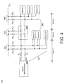
- FIG. 4 a simplified schematic view of another embodiment of the present invention is shown in which a single main system microprocessor 202 is coupled to I 2 C bus expansion circuit 204 via I 2 C bus 206. Furthermore, in the embodiment of Figure 4, additional components (i.e. devices 1'-M') other than I 2 C bus expansion circuit 204 are directly coupled to I 2 C bus 206. In the embodiment of Figure 4, three pull-up resistors 402, 404, and 406 are shown coupled to I 2 C bus 206, I 2 C bus expansion circuit 204, and I 2 C bus 205, respectively.
- the values for resistors 402, 404, and 406 must be properly selected. That is, resistors 402, 404, and 406 must be of a value such that such that the required time-constants on I 2 C buses 205 and 206 and on I 2 C bus expansion circuit 204 can be guaranteed.
- Zone 1 includes capacitance values associated with single main system microprocessor 202, the components coupled thereto (i.e. devices 1'-M'), and I 2 C bus 206;
- Zone 2 includes capacitance values associated with circuitry inside I 2 C bus expansion circuit 204;
- Zone 3 includes capacitance values associated with I 2 C bus 205 and the components coupled thereto (i.e. devices 1-N).
- the input capacitance associated with devices 1-N and 1'-M' is estimated to be, on average, 5-10 pF.
- C 1 refers to the capacitance present on I 2 C bus 206.
- some components e.g. devices 1'-M'
- other components e.g. devices 1-N
- I 2 C bus expansion circuit 204 7 components were coupled directly to I 2 C bus 206 while an additional 17 devices were coupled to I 2 C bus expansion circuit 204.
- the present embodiment fully utilizes the existing driving capabilities of single main system microprocessor 202 while, at the same time, reducing power consumption to a minimum.
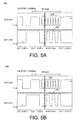
- Figure 5A illustrates clock (CLK) and data (DAT) waveforms measured from an I 2 C bus of a prior art single microprocessor system.
- CLK clock
- DAT data
- FIG. 5A wave peaks 502 and 504 are not square waveforms as was desired. That is, the signal distortion associated with the prior art single microprocessor system caused the waveforms to acquire an unwanted sawtooth-like shape.
- FIG. 5B illustrates clock (CLK) and data (DAT) waveforms measured from the I 2 C bus of one embodiment of a single main system microprocessor 202 having an impedance isolating expansion circuit 204 coupled thereto.
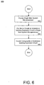
- FIG. 6 a flow chart 600 of steps performed in accordance with one embodiment of the present invention is shown. The following steps will be described with occasional reference to the elements of Figure 2 in order to further clarify the steps of Figure 6. As shown in step 602, the present embodiment first provides a single main system microprocessor 202.
- bus 206 is an I 2 C bus.
- additional components 240, 242, and 244 are coupled directly to bus 206.
- the present embodiment couples components (e.g. components 208-238) to impedance isolating expansion circuit 204 such that components 208-238 are not directly connected to bus 206 and such that components 208-238 do not induce an impedance load on bus 206.
- components e.g. components 208-2308
- an I 2 C bus 205 is used to couple components 208-238 to impedance isolating expansion circuit 204.
- the present invention allows single main system microprocessor 202 to operate effectively and without severe signal distortion.
- a single main system microprocessor is able to control operation of a device (e.g. a TV, an HDTV, a DVD player, or other consumer electronics device) with reliability and stability even when the device includes numerous components.
- the present embodiments provide a method and apparatus having a reduced number of system microprocessors in a device. Additionally, the present embodiments provide a method and apparatus which achieves the above-listed accomplishment and wherein the device does not impose prohibitively high driving requirements on the system microprocessor. The present embodiments further provide a method and apparatus which achieves both of the above-listed accomplishments and wherein the device does not suffer from severe signal distortion.
- At least embodiments of the invention provide an apparatus having a reduce number of controlling system microprocessors, said apparatus comprising: single main processing means for controlling operation of said apparatus: means for isolating impedance, bus means for coupling said single main processing means to said means for isolating impedance; a first component coupled to said means for isolating impedance such that said first component is not directly connected to said bus means and such that said first component does not induce a direct impedance load on said bus means.
- said bus means is comprised of an I 2 C bus.
- said means for isolating impedance is an I 2 C bus expansion circuit.
- the apparatus comprises second bus means for coupling said first component to said means for isolating impedance.
- said second bus means is comprised of an I 2 C bus.
- the apparatus comprises a second component coupled to said bus means.
- the apparatus comprises a plurality of said first components coupled to said means for isolating impedance; and a plurality of said second components coupled to said bus means.
Applications Claiming Priority (4)
| Application Number | Priority Date | Filing Date | Title |
|---|---|---|---|
| US9920998P | 1998-09-03 | 1998-09-03 | |
| US99209P | 1998-09-03 | ||
| US09/259,903 US6378024B1 (en) | 1999-02-26 | 1999-02-26 | Reduced microprocessor apparatus and method for device control system using impedance isolating expansion circuit |
| US259903 | 1999-02-28 |
Publications (2)
| Publication Number | Publication Date |
|---|---|
| EP0984623A2 true EP0984623A2 (de) | 2000-03-08 |
| EP0984623A3 EP0984623A3 (de) | 2001-05-02 |
Family
ID=26795769
Family Applications (1)
| Application Number | Title | Priority Date | Filing Date |
|---|---|---|---|
| EP99306960A Ceased EP0984623A3 (de) | 1998-09-03 | 1999-09-01 | Einrichtung mit einer eingeschränkten Anzahl von Mikroprozessoren und Verfahren für ein Gerätansteuerungssystem unter Verwendung einer impedanzisolierenden Expansionsschaltung |
Country Status (4)
| Country | Link |
|---|---|
| EP (1) | EP0984623A3 (de) |
| JP (1) | JP2000172631A (de) |
| KR (1) | KR100659218B1 (de) |
| CN (1) | CN1192306C (de) |
Families Citing this family (1)
| Publication number | Priority date | Publication date | Assignee | Title |
|---|---|---|---|---|
| CN100452011C (zh) * | 2005-10-18 | 2009-01-14 | 威盛电子股份有限公司 | 在总线上致能多处理器环境的装置和方法 |
Citations (2)
| Publication number | Priority date | Publication date | Assignee | Title |
|---|---|---|---|---|
| EP0506330A2 (de) * | 1991-03-29 | 1992-09-30 | Hitachi, Ltd. | Kommunikationssystem und Verfahren zum Steuern eines Systems |
| WO1997022184A2 (en) * | 1995-12-11 | 1997-06-19 | Philips Electronics N.V. | Bi-directional signal transmission system |
Family Cites Families (4)
| Publication number | Priority date | Publication date | Assignee | Title |
|---|---|---|---|---|
| US5287464A (en) * | 1990-10-24 | 1994-02-15 | Zilog, Inc. | Semiconductor multi-device system with logic means for controlling the operational mode of a set of input/output data bus drivers |
| US5428800A (en) * | 1991-10-30 | 1995-06-27 | I-Cube, Inc. | Input/output (I/O) bidirectional buffer for interfacing I/O ports of a field programmable interconnection device with array ports of a cross-point switch |
| JPH07321828A (ja) * | 1994-05-20 | 1995-12-08 | Fujitsu Ltd | 電子装置 |
| US5955889A (en) * | 1994-05-20 | 1999-09-21 | Fujitsu Limited | Electronic circuit apparatus for transmitting signals through a bus and semiconductor device for generating a predetermined stable voltage |
-
1999
- 1999-07-19 KR KR1019990029139A patent/KR100659218B1/ko not_active IP Right Cessation
- 1999-09-01 EP EP99306960A patent/EP0984623A3/de not_active Ceased
- 1999-09-03 JP JP11250867A patent/JP2000172631A/ja active Pending
- 1999-09-03 CN CNB991184963A patent/CN1192306C/zh not_active Expired - Fee Related
Patent Citations (2)
| Publication number | Priority date | Publication date | Assignee | Title |
|---|---|---|---|---|
| EP0506330A2 (de) * | 1991-03-29 | 1992-09-30 | Hitachi, Ltd. | Kommunikationssystem und Verfahren zum Steuern eines Systems |
| WO1997022184A2 (en) * | 1995-12-11 | 1997-06-19 | Philips Electronics N.V. | Bi-directional signal transmission system |
Non-Patent Citations (2)
| Title |
|---|
| "12C BUS BOOSTER" ELEKTOR ELECTRONICS,ELEKTOR PUBLISHERS LTD. CANTERBURY,GB, vol. 20, no. 223, 1 June 1994 (1994-06-01), pages 18-20, XP000483466 ISSN: 0268-4519 * |
| "I2C BUS MULTIPLEXOR" RESEARCH DISCLOSURE, vol. 42, no. 418, February 1999 (1999-02), XP002161473 /293, IBM, UK * |
Also Published As
| Publication number | Publication date |
|---|---|
| KR20000022667A (ko) | 2000-04-25 |
| EP0984623A3 (de) | 2001-05-02 |
| JP2000172631A (ja) | 2000-06-23 |
| CN1274885A (zh) | 2000-11-29 |
| KR100659218B1 (ko) | 2006-12-20 |
| CN1192306C (zh) | 2005-03-09 |
Similar Documents
| Publication | Publication Date | Title |
|---|---|---|
| KR0148018B1 (ko) | 텔레비젼 신호 스위칭 시스템 | |
| KR100263951B1 (ko) | 상호 연결 시스템용 장치 | |
| US6226053B1 (en) | Video line connection apparatus for adaptively connecting external input/output line | |
| US6378024B1 (en) | Reduced microprocessor apparatus and method for device control system using impedance isolating expansion circuit | |
| EP0984623A2 (de) | Einrichtung mit einer eingeschränkten Anzahl von Mikroprozessoren und Verfahren für ein Gerätansteuerungssystem unter Verwendung einer impedanzisolierenden Expansionsschaltung | |
| US7006161B2 (en) | Bus operation with integrated circuits in an unpowered state | |
| WO2003085953A2 (en) | Power-on detection of dvi receiver ic | |
| US5739714A (en) | Apparatus for controlling ground bounce | |
| US5414417A (en) | Automatic input/output terminal varying circuit | |
| US5539338A (en) | Input or output selectable circuit pin | |
| JP2687710B2 (ja) | 電源制御回路 | |
| EP0565170A2 (de) | Anordnung zum Gebrauch in einem System zur Verbindung von Geräten | |
| US20020021597A1 (en) | Semiconductor integrated circuit device | |
| US6279145B1 (en) | Apparatus and method for isolating noisy signals in an integrated circuit | |
| JPH057127A (ja) | 可変遅延回路 | |
| EP0849737A2 (de) | Verbesserungen an oder bezüglich elektronischen Systemen | |
| GB2218601A (en) | Preventing crosstalk in multi-input electronic device | |
| US5412482A (en) | Signal line changeover circuit with emitter followers | |
| JP3105041B2 (ja) | フレキシブル電子回路装置 | |
| JPH11135559A (ja) | 半導体機能設定電子機器 | |
| JP4891504B2 (ja) | パワーアップ状態用のトライステート回路 | |
| KR101129006B1 (ko) | 데이터 버스를 위한 능동 풀업 장치 | |
| US20040015250A1 (en) | Computer system with a plurality of audio and video output devices | |
| JP2905437B2 (ja) | ビデオ装置 | |
| KR920000353Y1 (ko) | 멀티 영상 입력단자를 갖는 칼러 텔레비젼의 영상 신호의 혼성 방지 회로 |
Legal Events
| Date | Code | Title | Description |
|---|---|---|---|
| PUAI | Public reference made under article 153(3) epc to a published international application that has entered the european phase |
Free format text: ORIGINAL CODE: 0009012 |
|
| AK | Designated contracting states |
Kind code of ref document: A2 Designated state(s): AT BE CH CY DE DK ES FI FR GB GR IE IT LI LU MC NL PT SE |
|
| AX | Request for extension of the european patent |
Free format text: AL;LT;LV;MK;RO;SI |
|
| PUAL | Search report despatched |
Free format text: ORIGINAL CODE: 0009013 |
|
| RIC1 | Information provided on ipc code assigned before grant |
Free format text: 7H 04N 5/14 A, 7G 06F 13/40 B |
|
| AK | Designated contracting states |
Kind code of ref document: A3 Designated state(s): AT BE CH CY DE DK ES FI FR GB GR IE IT LI LU MC NL PT SE |
|
| AX | Request for extension of the european patent |
Free format text: AL;LT;LV;MK;RO;SI |
|
| 17P | Request for examination filed |
Effective date: 20011010 |
|
| AKX | Designation fees paid |
Free format text: AT BE CH CY DE DK ES FI FR GB GR IE IT LI LU MC NL PT SE |
|
| 17Q | First examination report despatched |
Effective date: 20020129 |
|
| STAA | Information on the status of an ep patent application or granted ep patent |
Free format text: STATUS: THE APPLICATION HAS BEEN REFUSED |
|
| 18R | Application refused |
Effective date: 20040228 |