EP0982977A2 - Magnetkern für RF beschleunigenden Holraum und der Holraum - Google Patents
Magnetkern für RF beschleunigenden Holraum und der Holraum Download PDFInfo
- Publication number
- EP0982977A2 EP0982977A2 EP99116186A EP99116186A EP0982977A2 EP 0982977 A2 EP0982977 A2 EP 0982977A2 EP 99116186 A EP99116186 A EP 99116186A EP 99116186 A EP99116186 A EP 99116186A EP 0982977 A2 EP0982977 A2 EP 0982977A2
- Authority
- EP
- European Patent Office
- Prior art keywords
- magnetic core
- magnetic
- alloy
- cavity
- accelerating cavity
- Prior art date
- Legal status (The legal status is an assumption and is not a legal conclusion. Google has not performed a legal analysis and makes no representation as to the accuracy of the status listed.)
- Granted
Links
- 229910045601 alloy Inorganic materials 0.000 claims abstract description 33
- 239000000956 alloy Substances 0.000 claims abstract description 33
- 229910001004 magnetic alloy Inorganic materials 0.000 claims abstract description 15
- 239000006104 solid solution Substances 0.000 claims abstract description 5
- 229910052751 metal Inorganic materials 0.000 claims description 9
- 239000002184 metal Substances 0.000 claims description 9
- 238000012856 packing Methods 0.000 claims description 8
- 230000001133 acceleration Effects 0.000 claims description 3
- 229910052802 copper Inorganic materials 0.000 claims description 3
- 239000002159 nanocrystal Substances 0.000 claims description 3
- 229910052737 gold Inorganic materials 0.000 claims description 2
- 229910052735 hafnium Inorganic materials 0.000 claims description 2
- 229910052750 molybdenum Inorganic materials 0.000 claims description 2
- 229910052758 niobium Inorganic materials 0.000 claims description 2
- 229910052715 tantalum Inorganic materials 0.000 claims description 2
- 229910052719 titanium Inorganic materials 0.000 claims description 2
- 229910052721 tungsten Inorganic materials 0.000 claims description 2
- 229910052720 vanadium Inorganic materials 0.000 claims description 2
- 229910052726 zirconium Inorganic materials 0.000 claims description 2
- 239000011229 interlayer Substances 0.000 abstract description 21
- 238000009413 insulation Methods 0.000 abstract description 19
- 238000010438 heat treatment Methods 0.000 description 16
- 238000000034 method Methods 0.000 description 10
- 230000035699 permeability Effects 0.000 description 10
- 230000007423 decrease Effects 0.000 description 9
- 238000000465 moulding Methods 0.000 description 9
- VYPSYNLAJGMNEJ-UHFFFAOYSA-N Silicium dioxide Chemical compound O=[Si]=O VYPSYNLAJGMNEJ-UHFFFAOYSA-N 0.000 description 8
- 239000003822 epoxy resin Substances 0.000 description 6
- 229920000647 polyepoxide Polymers 0.000 description 6
- 239000012298 atmosphere Substances 0.000 description 5
- 238000010276 construction Methods 0.000 description 5
- 239000010949 copper Substances 0.000 description 5
- 238000004804 winding Methods 0.000 description 5
- 230000015572 biosynthetic process Effects 0.000 description 4
- 229910052681 coesite Inorganic materials 0.000 description 4
- 230000000052 comparative effect Effects 0.000 description 4
- 229910052906 cristobalite Inorganic materials 0.000 description 4
- 238000005520 cutting process Methods 0.000 description 4
- 238000010884 ion-beam technique Methods 0.000 description 4
- 238000003754 machining Methods 0.000 description 4
- 239000000377 silicon dioxide Substances 0.000 description 4
- 229910052682 stishovite Inorganic materials 0.000 description 4
- 229910052905 tridymite Inorganic materials 0.000 description 4
- IJGRMHOSHXDMSA-UHFFFAOYSA-N Atomic nitrogen Chemical compound N#N IJGRMHOSHXDMSA-UHFFFAOYSA-N 0.000 description 3
- 229910000521 B alloy Inorganic materials 0.000 description 3
- 229910008423 Si—B Inorganic materials 0.000 description 3
- 229910000808 amorphous metal alloy Inorganic materials 0.000 description 3
- 238000001816 cooling Methods 0.000 description 3
- 238000001035 drying Methods 0.000 description 3
- 230000004907 flux Effects 0.000 description 3
- 239000012212 insulator Substances 0.000 description 3
- 239000000463 material Substances 0.000 description 3
- 239000000126 substance Substances 0.000 description 3
- 229910000859 α-Fe Inorganic materials 0.000 description 3
- XKRFYHLGVUSROY-UHFFFAOYSA-N Argon Chemical compound [Ar] XKRFYHLGVUSROY-UHFFFAOYSA-N 0.000 description 2
- 229910018605 Ni—Zn Inorganic materials 0.000 description 2
- 239000007789 gas Substances 0.000 description 2
- LNEPOXFFQSENCJ-UHFFFAOYSA-N haloperidol Chemical compound C1CC(O)(C=2C=CC(Cl)=CC=2)CCN1CCCC(=O)C1=CC=C(F)C=C1 LNEPOXFFQSENCJ-UHFFFAOYSA-N 0.000 description 2
- 230000020169 heat generation Effects 0.000 description 2
- 239000000696 magnetic material Substances 0.000 description 2
- 238000004519 manufacturing process Methods 0.000 description 2
- 239000000203 mixture Substances 0.000 description 2
- 238000009740 moulding (composite fabrication) Methods 0.000 description 2
- 239000002245 particle Substances 0.000 description 2
- 229920001568 phenolic resin Polymers 0.000 description 2
- 239000005011 phenolic resin Substances 0.000 description 2
- 229920005989 resin Polymers 0.000 description 2
- 239000011347 resin Substances 0.000 description 2
- 239000002966 varnish Substances 0.000 description 2
- 229910001369 Brass Inorganic materials 0.000 description 1
- RYGMFSIKBFXOCR-UHFFFAOYSA-N Copper Chemical compound [Cu] RYGMFSIKBFXOCR-UHFFFAOYSA-N 0.000 description 1
- LFQSCWFLJHTTHZ-UHFFFAOYSA-N Ethanol Chemical compound CCO LFQSCWFLJHTTHZ-UHFFFAOYSA-N 0.000 description 1
- 229920002430 Fibre-reinforced plastic Polymers 0.000 description 1
- UFHFLCQGNIYNRP-UHFFFAOYSA-N Hydrogen Chemical compound [H][H] UFHFLCQGNIYNRP-UHFFFAOYSA-N 0.000 description 1
- 229910017262 Mo—B Inorganic materials 0.000 description 1
- 229910052782 aluminium Inorganic materials 0.000 description 1
- XAGFODPZIPBFFR-UHFFFAOYSA-N aluminium Chemical compound [Al] XAGFODPZIPBFFR-UHFFFAOYSA-N 0.000 description 1
- PNEYBMLMFCGWSK-UHFFFAOYSA-N aluminium oxide Inorganic materials [O-2].[O-2].[O-2].[Al+3].[Al+3] PNEYBMLMFCGWSK-UHFFFAOYSA-N 0.000 description 1
- 229910052786 argon Inorganic materials 0.000 description 1
- 230000005540 biological transmission Effects 0.000 description 1
- 239000010951 brass Substances 0.000 description 1
- 239000000919 ceramic Substances 0.000 description 1
- 239000000498 cooling water Substances 0.000 description 1
- 229910052593 corundum Inorganic materials 0.000 description 1
- 238000002425 crystallisation Methods 0.000 description 1
- 230000008025 crystallization Effects 0.000 description 1
- 230000007547 defect Effects 0.000 description 1
- 230000006866 deterioration Effects 0.000 description 1
- 229910001873 dinitrogen Inorganic materials 0.000 description 1
- 239000012772 electrical insulation material Substances 0.000 description 1
- 238000001962 electrophoresis Methods 0.000 description 1
- 238000005516 engineering process Methods 0.000 description 1
- 238000001704 evaporation Methods 0.000 description 1
- 239000011151 fibre-reinforced plastic Substances 0.000 description 1
- 238000000227 grinding Methods 0.000 description 1
- 238000009499 grossing Methods 0.000 description 1
- 239000001257 hydrogen Substances 0.000 description 1
- 150000002431 hydrogen Chemical class 0.000 description 1
- 229910052739 hydrogen Inorganic materials 0.000 description 1
- 238000007654 immersion Methods 0.000 description 1
- 239000011261 inert gas Substances 0.000 description 1
- 150000002500 ions Chemical class 0.000 description 1
- 239000010410 layer Substances 0.000 description 1
- 239000007788 liquid Substances 0.000 description 1
- CPLXHLVBOLITMK-UHFFFAOYSA-N magnesium oxide Inorganic materials [Mg]=O CPLXHLVBOLITMK-UHFFFAOYSA-N 0.000 description 1
- -1 modified alkyl silicate Chemical compound 0.000 description 1
- 229910052757 nitrogen Inorganic materials 0.000 description 1
- 239000012299 nitrogen atmosphere Substances 0.000 description 1
- 230000005658 nuclear physics Effects 0.000 description 1
- 230000001590 oxidative effect Effects 0.000 description 1
- 238000005498 polishing Methods 0.000 description 1
- 229920001721 polyimide Polymers 0.000 description 1
- 239000009719 polyimide resin Substances 0.000 description 1
- 239000000843 powder Substances 0.000 description 1
- 238000010791 quenching Methods 0.000 description 1
- 230000000171 quenching effect Effects 0.000 description 1
- 229920002050 silicone resin Polymers 0.000 description 1
- 239000000243 solution Substances 0.000 description 1
- 125000006850 spacer group Chemical group 0.000 description 1
- 238000005507 spraying Methods 0.000 description 1
- 238000004544 sputter deposition Methods 0.000 description 1
- 239000010935 stainless steel Substances 0.000 description 1
- 229910001220 stainless steel Inorganic materials 0.000 description 1
- XLYOFNOQVPJJNP-UHFFFAOYSA-N water Substances O XLYOFNOQVPJJNP-UHFFFAOYSA-N 0.000 description 1
- 229910001845 yogo sapphire Inorganic materials 0.000 description 1
Images
Classifications
-
- H—ELECTRICITY
- H01—ELECTRIC ELEMENTS
- H01F—MAGNETS; INDUCTANCES; TRANSFORMERS; SELECTION OF MATERIALS FOR THEIR MAGNETIC PROPERTIES
- H01F41/00—Apparatus or processes specially adapted for manufacturing or assembling magnets, inductances or transformers; Apparatus or processes specially adapted for manufacturing materials characterised by their magnetic properties
- H01F41/02—Apparatus or processes specially adapted for manufacturing or assembling magnets, inductances or transformers; Apparatus or processes specially adapted for manufacturing materials characterised by their magnetic properties for manufacturing cores, coils, or magnets
- H01F41/0206—Manufacturing of magnetic cores by mechanical means
- H01F41/0213—Manufacturing of magnetic circuits made from strip(s) or ribbon(s)
- H01F41/0226—Manufacturing of magnetic circuits made from strip(s) or ribbon(s) from amorphous ribbons
-
- H—ELECTRICITY
- H01—ELECTRIC ELEMENTS
- H01F—MAGNETS; INDUCTANCES; TRANSFORMERS; SELECTION OF MATERIALS FOR THEIR MAGNETIC PROPERTIES
- H01F1/00—Magnets or magnetic bodies characterised by the magnetic materials therefor; Selection of materials for their magnetic properties
- H01F1/01—Magnets or magnetic bodies characterised by the magnetic materials therefor; Selection of materials for their magnetic properties of inorganic materials
- H01F1/03—Magnets or magnetic bodies characterised by the magnetic materials therefor; Selection of materials for their magnetic properties of inorganic materials characterised by their coercivity
- H01F1/12—Magnets or magnetic bodies characterised by the magnetic materials therefor; Selection of materials for their magnetic properties of inorganic materials characterised by their coercivity of soft-magnetic materials
- H01F1/14—Magnets or magnetic bodies characterised by the magnetic materials therefor; Selection of materials for their magnetic properties of inorganic materials characterised by their coercivity of soft-magnetic materials metals or alloys
- H01F1/147—Alloys characterised by their composition
- H01F1/153—Amorphous metallic alloys, e.g. glassy metals
- H01F1/15333—Amorphous metallic alloys, e.g. glassy metals containing nanocrystallites, e.g. obtained by annealing
-
- H—ELECTRICITY
- H05—ELECTRIC TECHNIQUES NOT OTHERWISE PROVIDED FOR
- H05H—PLASMA TECHNIQUE; PRODUCTION OF ACCELERATED ELECTRICALLY-CHARGED PARTICLES OR OF NEUTRONS; PRODUCTION OR ACCELERATION OF NEUTRAL MOLECULAR OR ATOMIC BEAMS
- H05H7/00—Details of devices of the types covered by groups H05H9/00, H05H11/00, H05H13/00
- H05H7/04—Magnet systems, e.g. undulators, wigglers; Energisation thereof
Definitions
- the present invention relates to a magnetic core available for an RF accelerating cavity for accelerating charged particles and an RF accelerating cavity in which the magnetic core is used.
- particle accelerators have been widely used not only in the research of nuclear physics, but also in the development of high technologies in medical science, material science, life science, etc.
- an RF cavity for generating an RF voltage is needed for accelerating ions.
- an accelerating cavity with a frequency band of several MHz, in which a magnetic member is used in the resonator of the cavity is used.
- a high accelerating voltage is required especially when an accelerating cavity is used in high intensity proton accelerators.
- an RF accelerating cavity in which the magnetic member is loaded has an accelerating cavity 2 in the middle of a cylindrical vacuum duct 1 and magnetic cores 3b and 3c are oppositely loaded around the vacuum duct 1.
- a coaxial transmission line is composed of the vacuum duct 1 and an external cover 5.
- a bias power supply 6 is installed and coils are wound on the magnetic cores, thereby controlling the permeability of the magnetic cores in the external magnetic field formed by the bias current in order to increase the resonant frequency.
- Ni-Zn ferrite has been used in the magnetic core for the RF cavity. Recently it has been proposed to use, as an accelerating cavity, magnetic cores formed with a thin strip of nanocrystalline soft magnetic alloy disclosed in JP-A-6-333717 and JP-B2-2856130, in which fine nanoscale grains with a grain size less than 50 nm are formed with at least 50% of the alloy structure of the strip.
- the performance of a magnetic core for an accelerating cavity is evaluated by the ⁇ 'Qf-value in which ⁇ ', the real part of the complex permeability of the magnetic core at an operation frequency f, and the Q-value are used.
- An excellent accelerating cavity that operates with a small loss and with high efficiency can be obtained by using a magnetic core in which the ⁇ 'Qf' value is high.
- the Q-value is defined by the ratio of the real part ⁇ ' to the imaginary part ⁇ '' of the complex permeability, ⁇ '/ ⁇ '', and the higher this value is, the more excellent the performance of the magnetic core will be.
- the present invention was made in order to solve the above problems.
- an object of the invention is to provide a high-performance magnetic core with a high ⁇ 'Qf-value for an RF accelerating cavity and the RF accelerating cavity in which the magnetic core is used.
- the present inventors earnestly studied to make use of the properties of a thin strip of a nanocrystal soft magnetic alloy in an RF accelerating cavity. As a result, they found out that excellent properties can be obtained by forming the thin strip of the nanocrystalline soft magnetic alloy as a molded magnetic core and providing a gap at least in part of a magnetic path, and finally achieved the present invention.
- a molded magnetic core for an RF accelerating cavity comprising: a wound strip of a soft magnetic alloy which is provided with an insulating layer on at least one side thereof, and the metal structure of the alloy strip has nanocrystals of bcc-Fe solid solution whose average grain diameter is not more than 100 nm and whose volume fraction is not less than 50% in the metal structure, and at least one magnetic gap.
- a gap is provided at least in part of a magnetic path of the magnetic core.
- Stack cores formed by arranging the magnetic cores in series are oppositely arranged via a high-voltage gap, making it possible to provide an excellent RF accelerating cavity.
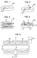
- FIG. 1 An example of shape of the magnetic core used in the accelerating cavity of the present invention is shown in Fig. 1.
- a gap 10 is provided in the magnetic path of a magnetic core 3a which is made of wound thin strips of a nanocrystalline soft magnetic alloy.
- the reason why the gap is needed in the invention is that the frequency at which magnetic resonance occurs shifts to the higher-frequency side by formation of the gap, thereby making it possible to increase the Q-value the MHz band. This results in an increase in the ⁇ 'Qf, showing a high-performance as accelerating cavity.
- gaps may be provided to the magnetic core as shown in Fig. 2. More gaps may be also acceptable.
- An electrical insulation material such as an epoxy resin can be filled in the gap.
- Cutting of the magnetic core for providing the cavity can be performed by a way using a grinding wheel, or other ways by means of an electric discharge wire machining, water jet, laser, etc.
- the cut section can be used as cut, eddy-current losses can be further reduced by smoothing the cut section by buffing or chemical polishing.
- the accelerating voltage of an RF accelerating cavity can be easily increased by making the magnetic core with a thin strip of a nanocrystalline soft magnetic alloy whose solid solution with an average grain size than 100 nm having a volume fraction of more than 50% of the whole alloy structure.
- molding the magnetic core of the present invention is indispensable for fixing interlayer-insulated thin alloy strips together, thereby preventing a cut section of the core from damaging by cutting.
- Epoxy resins, polyimide resins, phenolic resins, varnishes mainly composed of modified alkyl silicate, silicone resins, etc. are available for such molding. Molding is preferably performed in a vacuum or under a reduced pressure. This enables molding to be uniformly performed without occurrence of defects such as pinholes. After molding, the magnetic core may be cured at room temperature or at 100 to 200°C for several hours.
- FIG. 3 schematically shows a cross-sectional structure of a magnetic core which comprises interlayer insulation films.
- the magnetic core 3a is formed of a thin strip of nanocrystalline soft magnetic alloy 8 provided with an interlayer insulation film 7 and is molded with a resin 9.
- the thickness of the interlayer insulation film is preferably from 0.5 to 5 ⁇ m and more preferably from 1 to 3 ⁇ m. This is because there may sometimes be cases where the decrease in ⁇ ' due to eddy-current loss becomes remarkable with a thickness of the interlayer insulation film less than 0.5 ⁇ m and where ⁇ ' decreases due to stress in the magnetic core with a thickness of interlayer insulation film exceeding 5 ⁇ m, resulting in a decrease in the performance as an accelerating cavity.
- the interlayer insulation film may be made from SiO 2 , Al 2 O 3 , MgO, etc.
- the interlayer insulation film can be formed by following method, applying an alcohol solution containing metallic-alkoxide to the thin alloy strip and drying the same, adhering powders on the thin alloy strip by immersion, spraying or electrophoresis, forming a film by sputtering or evaporating, forming a film on the surface of the thin strip by heat treatment, etc.
- the thickness of the thin strip of the nanocrystalline soft magnetic alloy that forms the magnetic core for example, from 10 to 30 ⁇ m and is preferably from 15 to 25 ⁇ m. This is because there may sometimes be cases where it is difficult to produce a thin strip which is less than 10 ⁇ m in thickness and where, with a thickness of thin strip exceeding 30 ⁇ m, eddy-current losses of magnetic core increase, resulting in deterioration of the performance of the RF accelerating cavity or decrease in toughness of the thin strip.
- the packing factor of the magnetic core is preferably from 60 to 80% and more preferably from 65 to 75%.
- a high-performance magnetic core for the RF accelerating cavity can be obtained in this range.
- the packing factor can be defined as the spatial ratio of the volume occupied by the magnetic body only to the apparent volume of the magnetic core. This is because there may sometimes be cases, with a packing factor less than 60%, the magnetic core will be difficult to produce, with a packing factor exceeding 80%, the eddy-current losses of magnetic core increase, resulting in a decrease in the performance of the RF acceleratiing cavity.
- a thin strip of the nanocrystalline soft magnetic alloy may preferably comprise Fe as a primary element, at least one element selected from Cu and Au, and at least one element selected from the group consisting of Ti, V, Zr, Nb, Mo, Hf, Ta and W as essential elements, from which the magnetic core of the invention is formed.
- Fe-Cu-Nb-Zr-Si-B alloy, an Fe-Cu-Nb-Zr-Si-B alloy, an Fe-Mo-B alloy, an Fe-Nb-B alloy, an Fe-Zr-B alloy, an Fe-Cu-Zr-B alloy and an Fe-Nb-Al-Si-B alloy which are disclosed in JP-A-4-4393, can be available for the invention.
- a thin strip of an amorphous alloy is produced from a molten alloy having the above mentioned chemical composition by the liquid quenching method such as the single-roller process.
- the thin strip of the amorphous alloy may comprise a crystalline phase, it is desirable that the alloy as quenched has a mostly single amorphous phase in order to uniformly form nanoscale grains by subsequent heat treatment.
- the thin strip of the amorphous alloy is wound to produce the magnetic core, and subsequently be subjected to heat treatment.
- the heat treatment is indispensable for obtaining a nanocrystalline structure according to invention in which bcc solid solution with an average grain size of less than 100 nm has a volume fraction more than 50% in the whole alloy structure.
- the heat treatment temperature and time which depend on the size of the magnetic ore or the chemical composition of the thin alloy strip are generally from 450 to 700°C and from about 5 minutes to about 24 hours, respectively, and are preferably from 500 to 600°C and from 20 minutes to 6 hours, respectively. This is because, in the case less than 450°C, crystallization is hardly to occur, and because, in the case of the temperature exceeding 700°C, there is formation of non-uniform coarse grains.
- the heat treatment time is shorter than 5 minutes, it is difficult to obtain a uniform temperature over the whole magnetic core and ⁇ ' is liable to vary. If the heat treatment time is longer than 24 hours, not only productivity is bad, but also magnetic properties are liable to be deteriorated due to excessive grain growth and formation of non-uniform morphology grains. Vacuum, an inert gas atmosphere of nitrogen, argon, hydrogen, etc., and a reducing gas atmosphere are preferable for the heat treatment. However, the heat treatment may be also carried out in an oxidizing atmosphere as in air. Cooling may be selected optionally from air cooling, or cooling in a furnace.
- Heat treatment can be also performed in a magnetic field of AC or DC.
- Magnetic properties of the core can be improved by controlling magnetic anisotropy thereto by heat treatment in a magnetic field. It is unnecessary to apply a magnetic field in the whole period of heat treatment and it is good enough to apply a magnetic field only in the period during which the magnetic core is held at a temperature lower than the Curie temperature of the core. Intensity of the applied magnetic field is such a degree as may cause the magnetic core to magnetically saturate. In general, intensity of the magnetic field is preferably more than 1000 A/m.
- a gap is formed by cutting a part of the magnetic core.
- a spacer is inserted into the gap and the outside of the magnetic core is fastened with a nonmagnetic metal band.
- an inner core 11 made of a nonmagnetic metal, an insulator, etc. to fasten the outside of the magnetic with a band 12 made of a nonmagnetic metal, and to reinforce the magnetic core with a supporting plate 13 made of a nonmagnetic metal or an insulator.
- the nonmagnetic metal may be stainless steel, brass, aluminum, etc.
- the insulator may be epoxy resins, phenolic resins, fiber-reinforced plastics, ceramics, etc.
- the magnetic core In order to prevent heat generation from the magnetic core, it can be cooled by arranging a pipe made of a material with high thermal conductivity, for example, a copper pipe around the magnetic core and causing cooling water to circulate through the pipe.
- a pipe made of a material with high thermal conductivity for example, a copper pipe
- the RF accelerating cavity of the invention may be such as shown in Fig. 5. It can be fabricated by installing a stack core, which is formed by arranging in series the above magnetic cores for the RF cavity of the invention, as the magnetic core 3b and oppositely arranged magnetic core 3c formed by a similar stack core via an acceleration gap.
- the number of stacks of the magnetic cores 3a for the accelerating cavity of the invention that form the magnetic core 3b or magnetic core 3c used in the accelerating cavity of the invention is optionally selected according to the effective sectional area required of the magnetic core.
- a RF voltage is generated in the accelerating cavity by resonance between the inductance of the magnetic cores and the capacitance of the accelerating cavity and ion beams can be accelerated by the RF voltage.
- the orbiting speed increases with increasing accelerating energy of ion beams as with the conventional accelerating cavity and, therefore, it is desirable to increase the resonant frequency of the accelerating cavity with a lapse of time. It is possible to increase this resonant frequency by installing a bias power supply 6 and winding coils on the magnetic cores, thereby controlling the permeability of the magnetic cores in the external magnetic field formed by the bias current.
- a thin alloy strip of Fe ba1 Cu 1 Nb 3 Si 16 B 7 (at%) having a width of 25 mm and a thickness of 18 ⁇ m was produced by the single-roller method.
- a toroidal magnetic core of 900 mm in outer diameter, 300 mm in inner diameter and 25 mm in height was obtained by applying an interlayer insulation film of SiO 2 of 2 ⁇ m in thickness to both surfaces of the thin alloy strip and winding the thin alloy strip while applying and drying the interlayer insulating film. Thereafter, the magnetic core was subjected to heat treatment in a nitrogen atmosphere at 550°C for one hour without a magnetic field. Fine nanoscale-grains with an average grain size of 20 nm had a volume fraction of 80% in the whole alloy structure in the magnetic core.
- Table 1 shows the Q-values and ⁇ 'Qf-values of magnetic core measured with an LCR meter at frequencies of 0.5 to 10 MHz.
- the Q-values in the invention examples are remarkably high compared with those of the comparative examples. Since the ⁇ 'Qf-value is high, an excellent RF accelerating cavity which operates with high efficiency is obtained.
- the saturation magnetic flux density is 1.24 T and the Curie temperature is 570°C, both being high. Therefore, it is possible to increase the accelerating voltage of acceleration cavity.
- a thin alloy strip of Fe bal Cu 1.5 Nb 3.5 Zr 2.9 Si 0.3 B 6.4 (at %) having a width of 25 mm and a thickness of 15 ⁇ m was produced by the single-roller method.
- a toroidal magnetic core of 950 mm in outer diameter, 260 mm in inner diameter and 25 mm in height was obtained by winding the thin alloy strip while applying an interlayer insulation film of MgO to both surfaces of the thin alloy strip. Magnetic cores with a thickness of interlayer insulation film varied between 0 and 7 ⁇ m were made. Thereafter, each magnetic core was subjected to heat treatment in vacuum at 600°C for one hour without a magnetic field. Fine nanoscale grains with an average grain size of 15 nm had a volume fraction of 90% in the whole alloy structure in the magnetic core.
- Table 2 shows the real part ⁇ ' of the complex permeability of the magnetic cores made with varied thicknesses of interlayer insulation film at a frequency of 1 MHz.
- magnetic cores with an interlayer insulation film having a thickness of from 0.5 to 5 ⁇ m show high ⁇ ' and they are especially excellent as the magnetic core for the accelerating cavity.
- Thickness of interlayer insulating film ( ⁇ m) Real number part ⁇ ' of complex magnetic permeability at 1 MHz Remarks 0 300 Comparative Example 0.2 470 Invention Example 0.5 500 Ditto 1 515 Ditto 2 520 Ditto 3 515 Ditto 5 510 Ditto
- Thin alloy strips of Fe bal Nb 7.4 B 8.4 (at%) having a width of 25 mm were produced in varying thicknesses between 8 and 35 ⁇ m by the single-roller method.
- a toroidal magnetic core of 550 mm in outer diameter, 300 mm in inner diameter and 50 mm in height was obtained by winding the thin alloy strip while applying an interlayer insulation film of SiO 2 of 1.8 ⁇ m in thickness to one surface of this thin alloy strip. Thereafter, the magnetic core was subjected to heat treatment in an hydrogen gas atmosphere at 650°C for one hour without a magnetic field. Fine nanoscale grains with an average grain size of 12 nm had a volume fraction of 95% in the whole alloy structure in the magnetic core.
- part of the magnetic path was cut by electric discharge wire machining and gap 10 each having a distgance of 1 nm were formed in the magnetic path of magnetic core 3a as shown in Fig. 1.
- Table 3 shows the real part ⁇ ' of complex permeability and Q-values of the fabricated magnetic cores at a frequency of 1 MHz. It is apparent that magnet cores formed of a thin strip of nanocrystalline alloy with a thickness of from 10 to 30 ⁇ m show high ⁇ ' and that they are especially excellent as the magnetic core for the accelerating cavity. Thickness of thin strip ( ⁇ m) Real number part ⁇ ' of complex magnetic permeability at 1 MHz Q-value at 1 MHz Remarks 8 Unmeasurable Unmeasurable Production of a thin strip is difficult. 10 1700 4.3 Invention Example 15 1500 4.7 Ditto 20 1200 4.5 Ditto 25 1100 4.3 Ditto 30 1000 4.2 Ditto 33 890 3.0 Ditto 35 810 2.6 Ditto
- a thin alloy strip of Fe bal Cu 1 Nb 2 Si 7.5 B 12 (at%) having a width of 25 mm and a thickness of 25 ⁇ m was produced by the single-roller method.
- a toroidal magnetic core of 930 mm in outer diameter, 520 mm in inner diameter and 25 mm in height was obtained by applying an interlayer insulation film of SiO 2 to both surfaces of the thin alloy strip and winding the thin alloy strip while applying and drying the interlayer insulation film. Magnetic cores with a packing factor varied between 55 and 85% were obtained cores. Thereafter, each magnetic core was subjected to heat treatment in a nitrogen gas atmosphere at 530°C for one hour while applying a magnetic field of 1000 A/m in the direction of magnetic core height. Fine nanoscale grains with an average grain size of 25 nm had a volume fraction of 80% in the whole alloy structure of the magnetic core.
- Table 4 shows the real part ⁇ ' of complex permeability and Q-values of the fabricated magnetic cores at a frequency of 3 MHz.
- magnetic cores having a packing factor of from 60 to 80% show high ⁇ ' and Q-values and they are excellent magnetic cores for the accelerating cavity.
- Packing factor (%) Real number part ⁇ ' of complex magnetic permeability at 3 MHz Q-value at 3 MHz Remarks 55 Unmeasurable Unmeasurable Production of a thin strip is difficult.
- a high-performance magnetic core for an RF accelerating cavity and the RF accelerating cavity that operate in a stable manner under a high accelerating RF voltage.
Landscapes
- Engineering & Computer Science (AREA)
- Power Engineering (AREA)
- Physics & Mathematics (AREA)
- Chemical & Material Sciences (AREA)
- Crystallography & Structural Chemistry (AREA)
- Spectroscopy & Molecular Physics (AREA)
- Plasma & Fusion (AREA)
- Inorganic Chemistry (AREA)
- Materials Engineering (AREA)
- Electromagnetism (AREA)
- Dispersion Chemistry (AREA)
- Optics & Photonics (AREA)
- Manufacturing & Machinery (AREA)
- Particle Accelerators (AREA)
- Soft Magnetic Materials (AREA)
Applications Claiming Priority (4)
| Application Number | Priority Date | Filing Date | Title |
|---|---|---|---|
| JP23849198 | 1998-08-25 | ||
| JP23849198 | 1998-08-25 | ||
| JP9713899 | 1999-04-05 | ||
| JP09713899A JP3620784B2 (ja) | 1998-08-25 | 1999-04-05 | 高周波加速空胴用磁心およびこれを用いた高周波加速空胴 |
Publications (3)
| Publication Number | Publication Date |
|---|---|
| EP0982977A2 true EP0982977A2 (de) | 2000-03-01 |
| EP0982977A3 EP0982977A3 (de) | 2003-11-12 |
| EP0982977B1 EP0982977B1 (de) | 2004-12-29 |
Family
ID=26438346
Family Applications (1)
| Application Number | Title | Priority Date | Filing Date |
|---|---|---|---|
| EP99116186A Expired - Lifetime EP0982977B1 (de) | 1998-08-25 | 1999-08-24 | Magnetkern für RF beschleunigenden Hohlraum und der Hohlraum |
Country Status (4)
| Country | Link |
|---|---|
| US (1) | US6246172B1 (de) |
| EP (1) | EP0982977B1 (de) |
| JP (1) | JP3620784B2 (de) |
| DE (1) | DE69922891T2 (de) |
Cited By (3)
| Publication number | Priority date | Publication date | Assignee | Title |
|---|---|---|---|---|
| CN106104713A (zh) * | 2014-02-17 | 2016-11-09 | 日立金属株式会社 | 高频加速腔用磁芯及其制造方法 |
| CN110828132A (zh) * | 2019-11-08 | 2020-02-21 | 安徽昭田电子科技有限公司 | 一种开关模式电源用八卦扇形八分式组合铁氧体磁芯及其制造工艺 |
| EP4044773A4 (de) * | 2019-10-11 | 2023-12-20 | Kabushiki Kaisha Toshiba | Hochfrequenzbeschleunigungshohlraumkern und hochfrequenzbeschleunigungshohlraum damit |
Families Citing this family (16)
| Publication number | Priority date | Publication date | Assignee | Title |
|---|---|---|---|---|
| EP1166292A1 (de) * | 2000-01-12 | 2002-01-02 | Koninklijke Philips Electronics N.V. | Verfahren zur herstellung eines geschlossenen magnetkerns, magnetkern und magnetspule |
| US10431367B2 (en) * | 2005-09-22 | 2019-10-01 | Radial Electronics, Inc. | Method for gapping an embedded magnetic device |
| US7432516B2 (en) * | 2006-01-24 | 2008-10-07 | Brookhaven Science Associates, Llc | Rapid cycling medical synchrotron and beam delivery system |
| JP4858035B2 (ja) * | 2006-09-19 | 2012-01-18 | トヨタ自動車株式会社 | リアクトルのコアおよびリアクトル |
| US7411361B2 (en) * | 2006-11-30 | 2008-08-12 | Radiabeam Technologies Llc | Method and apparatus for radio frequency cavity |
| JP5442388B2 (ja) * | 2009-10-22 | 2014-03-12 | 株式会社日立産機システム | 磁性鉄心およびその製造方法、アキシャルギャップ型回転電機、静止機 |
| JP5271291B2 (ja) * | 2010-01-28 | 2013-08-21 | 株式会社エス・エッチ・ティ | 電流検出器 |
| JP5893892B2 (ja) * | 2011-10-31 | 2016-03-23 | 株式会社タムラ製作所 | リアクトル及びその製造方法 |
| JP2013247208A (ja) * | 2012-05-25 | 2013-12-09 | Hitachi Industrial Equipment Systems Co Ltd | 巻鉄心スコット変圧器 |
| DE102012218657A1 (de) * | 2012-10-12 | 2014-05-22 | Vacuumschmelze Gmbh & Co. Kg | Magnetkern, Verfahren und Vorrichtung zu dessen Herstellung und Verwendung eines solchen Magnetkerns |
| JP5782017B2 (ja) * | 2012-12-21 | 2015-09-24 | トヨタ自動車株式会社 | リアクトル及びその製造方法 |
| CN106030732B (zh) * | 2014-02-17 | 2018-09-04 | 日立金属株式会社 | 高频变压器磁芯及其制造方法 |
| KR101588966B1 (ko) * | 2014-08-11 | 2016-01-26 | 삼성전기주식회사 | 칩 전자부품 |
| KR102531245B1 (ko) * | 2017-01-06 | 2023-05-11 | (주)엘엑스하우시스 | 편상 나노결정립 합금 분말 및 이를 포함하는 복합 시트와 전자 기기 |
| JP6461418B1 (ja) * | 2018-10-16 | 2019-01-30 | 株式会社エス・エッチ・ティ | 電流検出器用のコア及びその製造方法 |
| JP6461419B1 (ja) * | 2018-10-16 | 2019-01-30 | 株式会社エス・エッチ・ティ | 電流検出器用のコア及びその製造方法 |
Family Cites Families (9)
| Publication number | Priority date | Publication date | Assignee | Title |
|---|---|---|---|---|
| US3976950A (en) * | 1975-03-20 | 1976-08-24 | The United States Of America As Represented By The United States Energy Research And Development Administration | Eccentric superconducting RF cavity separator structure |
| JP2573606B2 (ja) * | 1987-06-02 | 1997-01-22 | 日立金属 株式会社 | 磁心およびその製造方法 |
| CA2030446C (en) * | 1989-11-22 | 2001-01-23 | Yoshihito Yoshizawa | Magnetic alloy with ultrafine crystal grains and method of producing same |
| JP2986842B2 (ja) * | 1990-05-17 | 1999-12-06 | キヤノン電子株式会社 | 磁気ヘッドの製造方法 |
| US5111494A (en) * | 1990-08-28 | 1992-05-05 | North American Philips Corporation | Magnet for use in a drift tube of an x-ray tube |
| JP2909349B2 (ja) | 1993-05-21 | 1999-06-23 | 日立金属株式会社 | 絶縁膜が形成されたナノ結晶軟磁性合金薄帯および磁心ならびにパルス発生装置、レーザ装置、加速器 |
| US5661366A (en) * | 1994-11-04 | 1997-08-26 | Hitachi, Ltd. | Ion beam accelerating device having separately excited magnetic cores |
| JP2867933B2 (ja) * | 1995-12-14 | 1999-03-10 | 株式会社日立製作所 | 高周波加速装置及び環状加速器 |
| JP2856130B2 (ja) * | 1995-12-18 | 1999-02-10 | 株式会社日立製作所 | 高周波加速空胴 |
-
1999
- 1999-04-05 JP JP09713899A patent/JP3620784B2/ja not_active Expired - Lifetime
- 1999-08-24 DE DE69922891T patent/DE69922891T2/de not_active Expired - Lifetime
- 1999-08-24 US US09/379,804 patent/US6246172B1/en not_active Expired - Lifetime
- 1999-08-24 EP EP99116186A patent/EP0982977B1/de not_active Expired - Lifetime
Cited By (6)
| Publication number | Priority date | Publication date | Assignee | Title |
|---|---|---|---|---|
| CN106104713A (zh) * | 2014-02-17 | 2016-11-09 | 日立金属株式会社 | 高频加速腔用磁芯及其制造方法 |
| CN106104713B (zh) * | 2014-02-17 | 2019-03-01 | 日立金属株式会社 | 高频加速腔用磁芯及加速器的制造方法 |
| US10356890B2 (en) | 2014-02-17 | 2019-07-16 | Hitachi Metals, Ltd. | Core for high-frequency acceleration cavity, and manufacturing method thereof |
| EP4044773A4 (de) * | 2019-10-11 | 2023-12-20 | Kabushiki Kaisha Toshiba | Hochfrequenzbeschleunigungshohlraumkern und hochfrequenzbeschleunigungshohlraum damit |
| CN110828132A (zh) * | 2019-11-08 | 2020-02-21 | 安徽昭田电子科技有限公司 | 一种开关模式电源用八卦扇形八分式组合铁氧体磁芯及其制造工艺 |
| CN110828132B (zh) * | 2019-11-08 | 2020-10-13 | 安徽昭田电子科技有限公司 | 一种开关模式电源用八卦扇形八分式组合铁氧体磁芯及其制造工艺 |
Also Published As
| Publication number | Publication date |
|---|---|
| DE69922891D1 (de) | 2005-02-03 |
| EP0982977A3 (de) | 2003-11-12 |
| DE69922891T2 (de) | 2005-12-08 |
| EP0982977B1 (de) | 2004-12-29 |
| JP3620784B2 (ja) | 2005-02-16 |
| JP2000138099A (ja) | 2000-05-16 |
| US6246172B1 (en) | 2001-06-12 |
Similar Documents
| Publication | Publication Date | Title |
|---|---|---|
| EP0982977B1 (de) | Magnetkern für RF beschleunigenden Hohlraum und der Hohlraum | |
| KR940006334B1 (ko) | Fe기 연자성 합금, 그 제조방법 및 이를 이용한 자성코어 | |
| EP0302355B1 (de) | Weichmagnetisches Pulver aus einer auf Eisen basierenden Legierung, Magnetkern daraus und Herstellungsverfahren | |
| KR910002375B1 (ko) | 자성코어 및 그 제조방법 | |
| US7442263B2 (en) | Magnetic amplifier choke (magamp choke) with a magnetic core, use of magnetic amplifiers and method for producing softmagnetic cores for magnetic amplifiers | |
| EP0455113A2 (de) | Auf Fe basierende weichmagnetische Legierung, und diese Legierung enthaltendes Magnetmaterial und magnetischer Apparat, der diese Materialien verwendet | |
| JPH0680611B2 (ja) | 磁 心 | |
| US20100188186A1 (en) | Soft magnetic amorphous alloy | |
| EP3511958B1 (de) | Weichmagnetische legierung und magnetvorrichtung | |
| JP2004218037A (ja) | 高飽和磁束密度低損失磁性合金ならびにそれを用いた磁性部品 | |
| US6744342B2 (en) | High performance bulk metal magnetic component | |
| US7358844B2 (en) | Current transformer core and method for producing a current transformer core | |
| Luborsky et al. | The role of amorphous materials in the magnetics industry | |
| KR100518677B1 (ko) | 전기 초크 | |
| JP3424767B2 (ja) | ナノ結晶合金磁心およびナノ結晶合金磁心の熱処理方法 | |
| US6621399B2 (en) | Powder core and high-frequency reactor using the same | |
| JPH07135106A (ja) | 磁 心 | |
| US6788185B2 (en) | Powder core and high-frequency reactor using the same | |
| JP6845205B2 (ja) | 軟磁性合金薄帯および磁性部品 | |
| JP4851640B2 (ja) | 加速器用アモルファスコア及びそれを用いた加速器 | |
| CN114144851A (zh) | 铁基软磁合金、其制造方法以及包括其的磁性部件 | |
| KR102743729B1 (ko) | 합금 조성물, 합금 조성물로 이루어지는 합금 리본 및 합금 분말 | |
| KR102690071B1 (ko) | 인덕터 | |
| Ferch | Light transformers for kilowattt smps based on nanocrystalline softmagnetic cores | |
| Chen | Amorphous magnetic alloys for high frequency power electronic applications |
Legal Events
| Date | Code | Title | Description |
|---|---|---|---|
| PUAI | Public reference made under article 153(3) epc to a published international application that has entered the european phase |
Free format text: ORIGINAL CODE: 0009012 |
|
| AK | Designated contracting states |
Kind code of ref document: A2 Designated state(s): AT BE CH CY DE DK ES FI FR GB GR IE IT LI LU MC NL PT SE |
|
| AX | Request for extension of the european patent |
Free format text: AL;LT;LV;MK;RO;SI |
|
| PUAL | Search report despatched |
Free format text: ORIGINAL CODE: 0009013 |
|
| AK | Designated contracting states |
Kind code of ref document: A3 Designated state(s): AT BE CH CY DE DK ES FI FR GB GR IE IT LI LU MC NL PT SE |
|
| AX | Request for extension of the european patent |
Extension state: AL LT LV MK RO SI |
|
| 17P | Request for examination filed |
Effective date: 20040303 |
|
| GRAP | Despatch of communication of intention to grant a patent |
Free format text: ORIGINAL CODE: EPIDOSNIGR1 |
|
| AKX | Designation fees paid |
Designated state(s): DE FR |
|
| GRAS | Grant fee paid |
Free format text: ORIGINAL CODE: EPIDOSNIGR3 |
|
| GRAA | (expected) grant |
Free format text: ORIGINAL CODE: 0009210 |
|
| AK | Designated contracting states |
Kind code of ref document: B1 Designated state(s): DE FR |
|
| REG | Reference to a national code |
Ref country code: IE Ref legal event code: FG4D |
|
| REF | Corresponds to: |
Ref document number: 69922891 Country of ref document: DE Date of ref document: 20050203 Kind code of ref document: P |
|
| PLBE | No opposition filed within time limit |
Free format text: ORIGINAL CODE: 0009261 |
|
| STAA | Information on the status of an ep patent application or granted ep patent |
Free format text: STATUS: NO OPPOSITION FILED WITHIN TIME LIMIT |
|
| ET | Fr: translation filed | ||
| 26N | No opposition filed |
Effective date: 20050930 |
|
| REG | Reference to a national code |
Ref country code: FR Ref legal event code: PLFP Year of fee payment: 18 |
|
| REG | Reference to a national code |
Ref country code: FR Ref legal event code: PLFP Year of fee payment: 19 |
|
| REG | Reference to a national code |
Ref country code: FR Ref legal event code: PLFP Year of fee payment: 20 |
|
| PGFP | Annual fee paid to national office [announced via postgrant information from national office to epo] |
Ref country code: DE Payment date: 20180814 Year of fee payment: 20 Ref country code: FR Payment date: 20180712 Year of fee payment: 20 |
|
| REG | Reference to a national code |
Ref country code: DE Ref legal event code: R071 Ref document number: 69922891 Country of ref document: DE |