EP0982593B1 - Méthode de contrôle des procédés de pipettage - Google Patents
Méthode de contrôle des procédés de pipettage Download PDFInfo
- Publication number
- EP0982593B1 EP0982593B1 EP98115395A EP98115395A EP0982593B1 EP 0982593 B1 EP0982593 B1 EP 0982593B1 EP 98115395 A EP98115395 A EP 98115395A EP 98115395 A EP98115395 A EP 98115395A EP 0982593 B1 EP0982593 B1 EP 0982593B1
- Authority
- EP
- European Patent Office
- Prior art keywords
- liquid
- intensity
- process according
- light beam
- signal
- Prior art date
- Legal status (The legal status is an assumption and is not a legal conclusion. Google has not performed a legal analysis and makes no representation as to the accuracy of the status listed.)
- Expired - Lifetime
Links
Images

Classifications
-
- G—PHYSICS
- G01—MEASURING; TESTING
- G01N—INVESTIGATING OR ANALYSING MATERIALS BY DETERMINING THEIR CHEMICAL OR PHYSICAL PROPERTIES
- G01N35/00—Automatic analysis not limited to methods or materials provided for in any single one of groups G01N1/00 - G01N33/00; Handling materials therefor
- G01N35/10—Devices for transferring samples or any liquids to, in, or from, the analysis apparatus, e.g. suction devices, injection devices
- G01N35/1009—Characterised by arrangements for controlling the aspiration or dispense of liquids
- G01N35/1016—Control of the volume dispensed or introduced
- G01N2035/1018—Detecting inhomogeneities, e.g. foam, bubbles, clots
Definitions
- the present invention relates to a method for Monitoring of pipetting operations according to the The preamble of claim 1.
- Photocells with light source and receiver for example, to detect passing Objects are well known. It is further known that contained in a liquid jet gas bubbles due to their deviating from the beam optical density are recognizable. Leave gas bubbles in a liquid jet therefore, in principle, with the help of a suitable Detect light barrier. A facility for this is in the document WO97 / 33154.
- the invention is therefore based on the object Provide method of the type mentioned above, with the sucking in and the expulsion of the liquids from the pipetting needles of automatic analyzers to avoid analysis errors can be monitored as closely as possible.
- this effect is due to a non-contact, optical device done.
- the advantages associated with the inventive method particular is that it is compatible with its Help manages to perform measurements in automatic analyzers which are much more reliable than before, what the Meaningfulness of the measurements significantly improved.
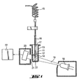
- a pipetting needle 12 As shown in Fig. 1, there is an ejected (first) liquid 11 in a pipetting needle 12. This Needle is inserted into a cuvette vessel 13 and dives with its tip into another (second) fluid 14, the the ejected liquid 11 is to be mixed. To the pipetting needle 12 is a flexible tube 15th connected via the suction or ejection of the Fluid 11 is controlled by pressure change. From the Pipetting needle 12 will be a minimum of 1 microliter Sample liquid 11 ejected.
- first liquid 11 Above the well-defined volume of the first liquid 11 is to delineate a (third), im Hose 15 and the upper portion of the pipetting needle 12th constantly remaining, serving hydraulic purposes Working fluid 16 is a separation bladder 17.
- a protective blister 27 In the top of Needle 12 to the first liquid 11 is located a protective blister 27, which the pipetting needle 12 against the outside quasi closed and thus especially unwanted leakage prevents portions of the first liquid 11.
- the device shown in Fig. 1 comprises a Light source 18, for example an LED (light emitting diode) for emitting a light beam 19 in the near infrared (e.g., at about 900 nm), and an associated light detector 20.
- a detector electronics 22 This is followed by a detector electronics 22.
- the light beam 19 passes through the cuvette vessel 13 and the contained therein liquid 14 relatively wide and oblique, whereby on occurrence of bubbles by total reflections the bladder walls at the detector 20 strong changes in received light intensity occur.
- the detector 20 is for Elimination of disturbing background radiation by a Screen 21 shielded against the outside. It can be on this Way also single, smallest bubbles prove, from the Needle 11 are ejected into the second liquid 14 and in this slowly ascend.
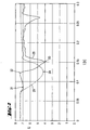
- FIG. 2 shows the typical course of the amplitude of the Output signal / intensity signal U of the light detector 20 as a function of time t in seconds for two different cases.
- the desired normal case is the required amount (first) liquid 11 bubble-free in the Pipetting needle 12 before.
- the full line 28 shows one Course of the signal U in the case of a normal pipetting. In this case it shows up after the beginning of the Ejection process a first minimum 31 shallow depth, which is caused by the ejected protective bubble 27. The following, relative maximum 32 goes to the ejected first liquid 11 back. Once this Liquid 11 completely from the pipetting needle 12th After a part of the separation bubble 17 follows, the a second, lower minimum 33 causes.
- the broken line 29 shows a course of the Output signal / intensity signal U in the second, unwanted case, with little or no Liquid 11, but mainly air from the Pipetting needle 12 introduced into the second liquid 14 becomes.
- this second case there is a single minimum 34, whose depth is about as deep as the main minimum 33 of the first case.
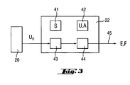
- FIG. 3 shows the block diagram of the detector electronics 22.
- This unit 22 comprises a first memory 41 and a second memory 42 as well as two logic circuits 43, 44. It outputs a control signal via the connection 45 to the outside and receives its measuring signals U n from the light detector 20.
- comparison values corresponding to the in 2 typical intensity / time courses correspond. These comparison values are preferably used as Thresholds S.
- the (n: consecutive numbering) 12 determined intensity values or the measurement signals U n during the ejection of the liquid from the pipetting needle 11 continuously stored so that each standing by a sequence of measurement values for processing.
- These measured values U n can be filtered to avoid statistical fluctuations, for example by averaging from z. B. in each case five adjacent individual values.
- the quotient of these difference values and a time interval, ie dU n / dt, corresponds to the respective gradients of the curves of FIG. 2.
- Important conclusions can already be drawn from these gradients, in particular from their mean values and the time points of application.
- the minima and / or maxima of the respective intensity / time curve can be determined from the sequence of the difference values dU n , and the associated intensities at the extreme points can be determined from the intensity values themselves. For example, FIG.
- first evaluation data B m (m: 1, 2, 3, ).
- the gradients b 12 and b 23 shown in FIG. 4 in the case of a course of the intensity U according to the curve 29 in FIG. 2 have clearly different values than the gradients b 12 and b 23 for FIG a curve of the intensity U according to the curve 28 in Fig. 2.
- the course of the intensity U according to the curve 29 in Fig. 2 corresponds to an undesired pipetting, in which little or no liquid 11, but mainly air from the Pipetting needle 12 is introduced into the second liquid 14.
- integrals A are used, ie surfaces are determined which are essentially limited by the intensity / time profiles according to FIG. 4 shows a scheme corresponding to FIG. 2.
- the integral Am corresponds to the area above the respective diagram curve, starting at the starting point t 1 and ending a predefined time ⁇ t later at the end point t 3 .
- the integral A tot corresponds to the assigned rectangular area, which is spanned by the said point t 1 and the time ⁇ t.
- the ratio A m / A tot of these respective integrals forms another evaluation date.
- the evaluation data becomes respectively with the one provided by the first memory 41 Thresholds compared.
- the logic circuit 44 via the Connection 45 either an end signal E or a Error signal F off.
- the detector electronics 22 can in a conventional manner Circuits, z. B. using Operational amplifiers, be constructed. In a preferred manner however, it is a programmatic Processor with associated memory, in which the Logic circuits 43, 44 by special program parts, the run in series, are realized.
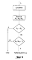
- FIG. 5 shows a very simple flow chart which represents the overall function of the detector electronics 22.
- the intensity values U n emitted by the detector 20 are stored as raw data in the memory 42. They are used in first processing steps to calculate the mentioned evaluation data B m , A m / A tot . This is followed essentially by two decision steps in which it is checked whether the first evaluation data B m corresponds to the conditions given by the stored threshold values S or not, and whether the ratio of the integrals A m / A tot does not exceed a further threshold value S i . If the decision answers correspond to the conditions in perfect pipetting, then there is a positive end signal. Otherwise, there may be an error. This result is either reacted with a hard stop signal or the repetition of the pipetting process is initiated.
- the thresholds S with comparable samples can be properly pre-determined.
- a zero balance is necessary, at least after each Initialization. This can be confounding factors how different volume amount of the second liquid 14, different transparency, refractive index and / or Viscosity of the liquids 11 and / or 14 and the Eliminate or at least minimize cuvette vessel 13.
- the favorable properties of the method according to the invention are based, above all, on its essentially dynamic principle, which consists in the skilful evaluation of a comprehensive series of measured values. Further, it is important to focus on two different types of values, one on the slopes dU n / dt and the other on integral A. This greatly increases the ability to make decisions in detecting any errors.
- a device for monitoring pipetting operations, and in particular the leakage of a first liquid 11 from a pipetting needle 12, which is immersed with its tip in a second liquid 14, has been described above.
- This device comprises a source 18 for a light beam 19, which extends transversely to the path of the first liquid 11, and a light detector 20 at the end of the light beam 19 for outputting an output signal corresponding to the respective received light intensity.
- the detector 20 is designed for the continuous output of intensity signals or measuring signals U n .
- the device further includes a first store 41 for predetermined threshold values S, a second store 42 for the current intensity signals or measurement signals U n and for evaluation data B m , A m / A tot derived therefrom, and at least one logic circuit 43, 44 for comparison the evaluation data B m , A m / A dead with the thresholds S and for outputting a result signal E, F.
Landscapes
- Immunology (AREA)
- Analytical Chemistry (AREA)
- Physics & Mathematics (AREA)
- Chemical & Material Sciences (AREA)
- Pathology (AREA)
- Biochemistry (AREA)
- General Health & Medical Sciences (AREA)
- General Physics & Mathematics (AREA)
- Life Sciences & Earth Sciences (AREA)
- Health & Medical Sciences (AREA)
- Investigating Or Analysing Materials By Optical Means (AREA)
- Automatic Analysis And Handling Materials Therefor (AREA)
- Sampling And Sample Adjustment (AREA)
- Length Measuring Devices By Optical Means (AREA)
- Pipeline Systems (AREA)
- Investigating Or Analyzing Materials By The Use Of Ultrasonic Waves (AREA)
- Measurement Of Levels Of Liquids Or Fluent Solid Materials (AREA)
Claims (10)
- Procédé de contrôle de processus de pipettage et, en particulier, de la sortie d'un premier liquide provenant d'une aiguille de pipettage (12) qui est plongée, par sa pointe, dans un deuxième liquide (14) contenu dans un récipient (13),
caractérisé en ce quele deuxième liquide (14) est irradié par un faisceau lumineux (19) fourni par une source lumineuse (18),le faisceau lumineux (19) traverse le récipient (13) et une zone du deuxième liquide (14), laquelle zone s'étend depuis une paroi intérieure jusqu'à la paroi intérieure opposée du récipient,le faisceau lumineux (19) sortant du deuxième liquide (14) est capté par un détecteur de lumière (20) qui fournit un signal d'intensité (U) servant de signal de sortie qui correspond à l'intensité lumineuse captée,des valeurs mesurées du signal d'intensité (U) sont mesurées et mémorisées en continu, etdes données d'évaluation sont déduites des valeurs mesurées et mémorisées du signal d'intensité (U) et ces données d'évaluation sont comparées à des valeurs de seuil prédéterminées, pour produire un signal de résultat. - Procédé selon la revendication 1,
caractérisé en ce que des premières données parmi les données d'évaluation déduites (Bm) sont des pentes de courbes du diagramme du rapport intensité / temps. - Procédé selon la revendication 1,
caractérisé en ce que des deuxièmes données parmi les données d'évaluation déduites sont le quotient de deux intégrales (Am/Atot), intégrales auxquelles correspondent deux surfaces dans ledit diagramme du rapport intensité / temps, lesquelles surfaces sont matérialisées par un point de départ (U1) et par un intervalle de temps (Δt). - Procédé selon la revendication 1,
caractérisé en ce que des valeurs mesurées sont obtenues par un calcul de la moyenne des amplitudes de signaux d'intensité voisins (Un) . - Procédé selon l'une quelconque des revendications 1 à 4, caractérisé en ce que le volume du premier liquide expulsé (11) est au minimum à peu près égal à 1 microlitre.
- Procédé permettant de constater la formation de bulles d'air avec un premier liquide sortant d'une aiguille de pipettage (12) qui est plongée, par sa pointe, dans un deuxième liquide (14) contenu dans un récipient (13),
caractérisé en ce quele deuxième liquide (14) est irradié par un faisceau lumineux (19) fourni par une source lumineuse (18),le faisceau lumineux (19) traverse le récipient (13) et une zone du deuxième liquide (14), laquelle zone s'étend depuis une paroi intérieure jusqu'à la paroi intérieure opposée du récipient,le faisceau lumineux (19) sortant du deuxième liquide (14) est capté par un détecteur de lumière (20) qui fournit un signal d'intensité (U) servant de signal de sortie qui correspond à l'intensité lumineuse captée,des valeurs mesurées du signal d'intensité (U) sont mesurées et mémorisées en continu, etdes données d'évaluation sont déduites des valeurs mesurées et mémorisées du signal d'intensité (U) et ces données d'évaluation sont comparées à des valeurs de seuil prédéterminées, pour produire un signal de résultat. - Procédé selon la revendication 6,
caractérisé en ce que des premières données parmi les données d'évaluation déduites (Bm) sont des pentes de courbes du diagramme du rapport intensité / temps. - Procédé selon la revendication 6,
caractérisé en ce que des deuxièmes données parmi les données d'évaluation déduites sont le quotient de deux intégrales (Am/Atot), intégrales auxquelles correspondent deux surfaces dans ledit diagramme du rapport intensité / temps, lesquelles surfaces sont matérialisées par un point de départ (U1) et par un intervalle de temps (Δt). - Procédé selon la revendication 6,
caractérisé en ce que des valeurs mesurées sont obtenues par un calcul de la moyenne des amplitudes de signaux d'intensité voisins (Un). - Procédé selon l'une quelconque des revendications 6 à 9, caractérisé en ce que le volume du premier liquide expulsé (11) est au minimum à peu près égal à 1 microlitre.
Priority Applications (6)
| Application Number | Priority Date | Filing Date | Title |
|---|---|---|---|
| EP98115395A EP0982593B1 (fr) | 1998-08-17 | 1998-08-17 | Méthode de contrôle des procédés de pipettage |
| DE59813265T DE59813265D1 (de) | 1998-08-17 | 1998-08-17 | Verfahren zur Ueberwachung von Pipettiervorgängen |
| ES98115395T ES2253797T3 (es) | 1998-08-17 | 1998-08-17 | Dispositivo para el control de los procesos de pipeteado. |
| AT98115395T ATE312355T1 (de) | 1998-08-17 | 1998-08-17 | Verfahren zur ueberwachung von pipettiervorgängen |
| US09/371,979 US6281517B1 (en) | 1998-08-17 | 1999-08-11 | Apparatus for monitoring pipetting operations |
| JP23002699A JP4355059B2 (ja) | 1998-08-17 | 1999-08-16 | 分注動作の監視装置 |
Applications Claiming Priority (1)
| Application Number | Priority Date | Filing Date | Title |
|---|---|---|---|
| EP98115395A EP0982593B1 (fr) | 1998-08-17 | 1998-08-17 | Méthode de contrôle des procédés de pipettage |
Publications (2)
| Publication Number | Publication Date |
|---|---|
| EP0982593A1 EP0982593A1 (fr) | 2000-03-01 |
| EP0982593B1 true EP0982593B1 (fr) | 2005-12-07 |
Family
ID=8232464
Family Applications (1)
| Application Number | Title | Priority Date | Filing Date |
|---|---|---|---|
| EP98115395A Expired - Lifetime EP0982593B1 (fr) | 1998-08-17 | 1998-08-17 | Méthode de contrôle des procédés de pipettage |
Country Status (6)
| Country | Link |
|---|---|
| US (1) | US6281517B1 (fr) |
| EP (1) | EP0982593B1 (fr) |
| JP (1) | JP4355059B2 (fr) |
| AT (1) | ATE312355T1 (fr) |
| DE (1) | DE59813265D1 (fr) |
| ES (1) | ES2253797T3 (fr) |
Cited By (1)
| Publication number | Priority date | Publication date | Assignee | Title |
|---|---|---|---|---|
| DE102017212196A1 (de) * | 2017-07-17 | 2019-01-17 | Robert Bosch Gmbh | Verfahren und Steuergerät zum Detektieren von Blasen in einer Fluidkammer eines fluidischen Systems und fluidisches System |
Families Citing this family (8)
| Publication number | Priority date | Publication date | Assignee | Title |
|---|---|---|---|---|
| AU2004201406B2 (en) * | 1996-08-16 | 2007-05-17 | Ge Healthcare Niagara Inc. | A digital imaging system for assays in well plates, gels and blots |
| ATE313805T1 (de) | 2001-03-09 | 2006-01-15 | Hamilton Bonaduz Ag | Verfahren und vorrichtung zur beurteilung eines flüssigkeitsdosierungsvorgangs |
| US20070031818A1 (en) * | 2004-07-15 | 2007-02-08 | Cytokinetics, Inc., A Delaware Corporation | Assay for distinguishing live and dead cells |
| JP4593404B2 (ja) | 2005-08-29 | 2010-12-08 | シスメックス株式会社 | 液体試料吸引監視方法及び装置、並びに液体試料分析装置 |
| US8165919B2 (en) | 2006-03-31 | 2012-04-24 | Digital River, Inc. | Web based product ordering method with shopping carts actions queued |
| EP2031403B1 (fr) * | 2007-08-27 | 2016-02-17 | Roche Diagnostics GmbH | Procédé de surveillance d'un procédé de transfert de fluides |
| EP2112514A1 (fr) * | 2008-04-24 | 2009-10-28 | bioMérieux BV | Procédé et appareil de vérification du fluide dans l'extrémité d'une pipette |
| CN110941855B (zh) * | 2019-11-26 | 2022-02-15 | 电子科技大学 | 一种AIoT场景下的神经网络模型窃取防御方法 |
Citations (1)
| Publication number | Priority date | Publication date | Assignee | Title |
|---|---|---|---|---|
| WO1996032649A1 (fr) * | 1995-04-11 | 1996-10-17 | Precision System Science Co., Ltd. | Methode de test d'aspiration liquide et appareil de distribution commande par ce procede |
Family Cites Families (9)
| Publication number | Priority date | Publication date | Assignee | Title |
|---|---|---|---|---|
| CH587486A5 (fr) * | 1974-11-29 | 1977-05-13 | Hoffmann La Roche | |
| EP0038912B1 (fr) * | 1980-04-23 | 1983-05-18 | Contraves Ag | Canule pourvue de moyens détecteurs |
| US5125748A (en) * | 1986-03-26 | 1992-06-30 | Beckman Instruments, Inc. | Optical detection module for use in an automated laboratory work station |
| US4979821A (en) * | 1988-01-27 | 1990-12-25 | Ortho Diagnostic Systems Inc. | Cuvette for receiving liquid sample |
| JPH0781996B2 (ja) * | 1988-08-27 | 1995-09-06 | 株式会社日立製作所 | オートサンプラ |
| JPH05223830A (ja) * | 1991-04-04 | 1993-09-03 | Olympus Optical Co Ltd | 分注量検出装置および方法 |
| US5559339A (en) * | 1994-10-31 | 1996-09-24 | Abbott Laboratories | Method and apparatus for verifying dispense of a fluid from a dispense nozzle |
| SE506546C2 (sv) * | 1996-03-07 | 1998-01-12 | Octagon Ab | Bubbeldetektor |
| DE19630160A1 (de) * | 1996-07-26 | 1998-01-29 | Boehringer Mannheim Gmbh | Analysesystem mit Mitteln zur Erkennung von Unterdosierungen |
-
1998
- 1998-08-17 EP EP98115395A patent/EP0982593B1/fr not_active Expired - Lifetime
- 1998-08-17 AT AT98115395T patent/ATE312355T1/de not_active IP Right Cessation
- 1998-08-17 ES ES98115395T patent/ES2253797T3/es not_active Expired - Lifetime
- 1998-08-17 DE DE59813265T patent/DE59813265D1/de not_active Expired - Lifetime
-
1999
- 1999-08-11 US US09/371,979 patent/US6281517B1/en not_active Expired - Fee Related
- 1999-08-16 JP JP23002699A patent/JP4355059B2/ja not_active Expired - Fee Related
Patent Citations (1)
| Publication number | Priority date | Publication date | Assignee | Title |
|---|---|---|---|---|
| WO1996032649A1 (fr) * | 1995-04-11 | 1996-10-17 | Precision System Science Co., Ltd. | Methode de test d'aspiration liquide et appareil de distribution commande par ce procede |
Cited By (1)
| Publication number | Priority date | Publication date | Assignee | Title |
|---|---|---|---|---|
| DE102017212196A1 (de) * | 2017-07-17 | 2019-01-17 | Robert Bosch Gmbh | Verfahren und Steuergerät zum Detektieren von Blasen in einer Fluidkammer eines fluidischen Systems und fluidisches System |
Also Published As
| Publication number | Publication date |
|---|---|
| US6281517B1 (en) | 2001-08-28 |
| ATE312355T1 (de) | 2005-12-15 |
| JP2000088865A (ja) | 2000-03-31 |
| DE59813265D1 (de) | 2006-01-12 |
| EP0982593A1 (fr) | 2000-03-01 |
| JP4355059B2 (ja) | 2009-10-28 |
| ES2253797T3 (es) | 2006-06-01 |
Similar Documents
| Publication | Publication Date | Title |
|---|---|---|
| DE69630005T2 (de) | Analysator und Methode zur Analyse von Urinbestandteilen | |
| DE69635705T2 (de) | Prüfverfahren mit flüssigkeitsansaugung und mit diesem verfahren kontrolliertes abgabegerät | |
| DE69635150T2 (de) | Verfahren und Vorrichtung zur Verwaltung von Reagenzien | |
| EP2260290B1 (fr) | Procédé et dispositif de mesure de turbidité | |
| DE69116041T2 (de) | Vorrichtung und Verfahren zum Aufspüren von anwesendem Gas in einer Bohrlochflüssigkeitsströmung | |
| DE69422883T4 (de) | Teilchenanalysator | |
| DE69913424T2 (de) | Inkrementaler Absorptionsabtastung von Flüssigkeit in einer Abgabespitze | |
| DE3009835A1 (de) | Verfahren und vorrichtung zur bestimmung der eigenschaften eines segmentierten fluids, ohne in das fluid einzudringen | |
| EP0982593B1 (fr) | Méthode de contrôle des procédés de pipettage | |
| DE2436110B2 (de) | Vorrichtung zur Feststellung von Herstellungsfehlern in einer bewegten Materialbahn | |
| DE2459111C3 (de) | Verfahren und Vorrichtung zur photometrischen Analyse flüssiger Proben | |
| DE102006052833A1 (de) | Verfahren zum Feststellen einer Verstopfung, eines Koagels oder eines Pfropfens an der Aufnahmeöffnung einer Dosiernadel | |
| DE69322122T2 (de) | Verfahren und Vorrichtung zur Überwachung der Abgabe einer Flüssigkeit | |
| DE69622978T2 (de) | Analysator zur Analyse von Urinbestandteilen | |
| EP0025921B1 (fr) | Dispositif pour mesurer la tension de surface | |
| DE2718330A1 (de) | Geraet zum analysieren von blut | |
| DE69525570T2 (de) | Probensammler für flüssige Proben | |
| DE3418283A1 (de) | Verfahren zum nachweis von fehlstellen in transparenten materialien | |
| DE69223029T2 (de) | Faserlängenanalysierer | |
| DE3307789A1 (de) | Verfahren und vorrichtung zur anzeige einer aenderung des zerfallpunktes in einem tropfenerzeugungssystem | |
| DE2419362A1 (de) | Verfahren und vorrichtung zum ermitteln der form von zellkernen | |
| EP3136083B1 (fr) | Procede et dispositif de determination d'une matiere ou d'une concentration de matiere dans un milieu liquide | |
| DE3779744T2 (de) | Verfahren und vorrichtung zum nachweis von fremdkoerpern, wie luftblaeschen in einer fluessigkeit. | |
| DE2134937C2 (de) | Verfahren und Vorrichtung zum Erfassen von in einer Flüssigkeit suspendierten Teilchen | |
| DE4117024C2 (de) | Vorrichtung zum Auswerten von Aggregationsbildern |
Legal Events
| Date | Code | Title | Description |
|---|---|---|---|
| PUAI | Public reference made under article 153(3) epc to a published international application that has entered the european phase |
Free format text: ORIGINAL CODE: 0009012 |
|
| AK | Designated contracting states |
Kind code of ref document: A1 Designated state(s): AT CH DE ES FR GB IT LI NL |
|
| AX | Request for extension of the european patent |
Free format text: AL;LT;LV;MK;RO;SI |
|
| 17P | Request for examination filed |
Effective date: 20000624 |
|
| AKX | Designation fees paid |
Free format text: AT CH DE ES FR GB IT LI NL |
|
| 17Q | First examination report despatched |
Effective date: 20040716 |
|
| GRAP | Despatch of communication of intention to grant a patent |
Free format text: ORIGINAL CODE: EPIDOSNIGR1 |
|
| RTI1 | Title (correction) |
Free format text: METHOD FOR MONITORING PIPETTING OPERATIONS |
|
| GRAS | Grant fee paid |
Free format text: ORIGINAL CODE: EPIDOSNIGR3 |
|
| GRAA | (expected) grant |
Free format text: ORIGINAL CODE: 0009210 |
|
| AK | Designated contracting states |
Kind code of ref document: B1 Designated state(s): AT CH DE ES FR GB IT LI NL |
|
| REG | Reference to a national code |
Ref country code: GB Ref legal event code: FG4D Free format text: NOT ENGLISH |
|
| REG | Reference to a national code |
Ref country code: CH Ref legal event code: NV Representative=s name: VENTOCILLA PATENT AG Ref country code: CH Ref legal event code: EP |
|
| REF | Corresponds to: |
Ref document number: 59813265 Country of ref document: DE Date of ref document: 20060112 Kind code of ref document: P |
|
| GBT | Gb: translation of ep patent filed (gb section 77(6)(a)/1977) |
Effective date: 20060315 |
|
| REG | Reference to a national code |
Ref country code: ES Ref legal event code: FG2A Ref document number: 2253797 Country of ref document: ES Kind code of ref document: T3 |
|
| ET | Fr: translation filed | ||
| PLBE | No opposition filed within time limit |
Free format text: ORIGINAL CODE: 0009261 |
|
| STAA | Information on the status of an ep patent application or granted ep patent |
Free format text: STATUS: NO OPPOSITION FILED WITHIN TIME LIMIT |
|
| 26N | No opposition filed |
Effective date: 20060908 |
|
| PGFP | Annual fee paid to national office [announced via postgrant information from national office to epo] |
Ref country code: NL Payment date: 20080715 Year of fee payment: 11 Ref country code: CH Payment date: 20080708 Year of fee payment: 11 |
|
| PGFP | Annual fee paid to national office [announced via postgrant information from national office to epo] |
Ref country code: AT Payment date: 20080708 Year of fee payment: 11 |
|
| REG | Reference to a national code |
Ref country code: NL Ref legal event code: V1 Effective date: 20100301 Ref country code: CH Ref legal event code: PL |
|
| PG25 | Lapsed in a contracting state [announced via postgrant information from national office to epo] |
Ref country code: LI Free format text: LAPSE BECAUSE OF NON-PAYMENT OF DUE FEES Effective date: 20090831 Ref country code: CH Free format text: LAPSE BECAUSE OF NON-PAYMENT OF DUE FEES Effective date: 20090831 |
|
| PG25 | Lapsed in a contracting state [announced via postgrant information from national office to epo] |
Ref country code: AT Free format text: LAPSE BECAUSE OF NON-PAYMENT OF DUE FEES Effective date: 20090817 |
|
| PG25 | Lapsed in a contracting state [announced via postgrant information from national office to epo] |
Ref country code: NL Free format text: LAPSE BECAUSE OF NON-PAYMENT OF DUE FEES Effective date: 20100301 |
|
| PGFP | Annual fee paid to national office [announced via postgrant information from national office to epo] |
Ref country code: GB Payment date: 20120726 Year of fee payment: 15 |
|
| PGFP | Annual fee paid to national office [announced via postgrant information from national office to epo] |
Ref country code: ES Payment date: 20120809 Year of fee payment: 15 Ref country code: DE Payment date: 20120831 Year of fee payment: 15 Ref country code: IT Payment date: 20120820 Year of fee payment: 15 Ref country code: FR Payment date: 20120809 Year of fee payment: 15 |
|
| GBPC | Gb: european patent ceased through non-payment of renewal fee |
Effective date: 20130817 |
|
| PG25 | Lapsed in a contracting state [announced via postgrant information from national office to epo] |
Ref country code: DE Free format text: LAPSE BECAUSE OF NON-PAYMENT OF DUE FEES Effective date: 20140301 |
|
| REG | Reference to a national code |
Ref country code: FR Ref legal event code: ST Effective date: 20140430 |
|
| PG25 | Lapsed in a contracting state [announced via postgrant information from national office to epo] |
Ref country code: IT Free format text: LAPSE BECAUSE OF NON-PAYMENT OF DUE FEES Effective date: 20130817 |
|
| REG | Reference to a national code |
Ref country code: DE Ref legal event code: R119 Ref document number: 59813265 Country of ref document: DE Effective date: 20140301 |
|
| PG25 | Lapsed in a contracting state [announced via postgrant information from national office to epo] |
Ref country code: GB Free format text: LAPSE BECAUSE OF NON-PAYMENT OF DUE FEES Effective date: 20130817 |
|
| PG25 | Lapsed in a contracting state [announced via postgrant information from national office to epo] |
Ref country code: FR Free format text: LAPSE BECAUSE OF NON-PAYMENT OF DUE FEES Effective date: 20130902 |
|
| PG25 | Lapsed in a contracting state [announced via postgrant information from national office to epo] |
Ref country code: ES Free format text: LAPSE BECAUSE OF NON-PAYMENT OF DUE FEES Effective date: 20130818 |