EP0982508B1 - Arbre/palier composé et moteur de broche et bras pivotant pour un entraínement de disque dur comportant un tel palier - Google Patents
Arbre/palier composé et moteur de broche et bras pivotant pour un entraínement de disque dur comportant un tel palier Download PDFInfo
- Publication number
- EP0982508B1 EP0982508B1 EP19990306831 EP99306831A EP0982508B1 EP 0982508 B1 EP0982508 B1 EP 0982508B1 EP 19990306831 EP19990306831 EP 19990306831 EP 99306831 A EP99306831 A EP 99306831A EP 0982508 B1 EP0982508 B1 EP 0982508B1
- Authority
- EP
- European Patent Office
- Prior art keywords
- peripheral surface
- race
- sealing plate
- inner peripheral
- shaft portion
- Prior art date
- Legal status (The legal status is an assumption and is not a legal conclusion. Google has not performed a legal analysis and makes no representation as to the accuracy of the status listed.)
- Expired - Lifetime
Links
Images

Classifications
-
- H—ELECTRICITY
- H02—GENERATION; CONVERSION OR DISTRIBUTION OF ELECTRIC POWER
- H02K—DYNAMO-ELECTRIC MACHINES
- H02K5/00—Casings; Enclosures; Supports
- H02K5/04—Casings or enclosures characterised by the shape, form or construction thereof
- H02K5/16—Means for supporting bearings, e.g. insulating supports or means for fitting bearings in the bearing-shields
- H02K5/173—Means for supporting bearings, e.g. insulating supports or means for fitting bearings in the bearing-shields using bearings with rolling contact, e.g. ball bearings
- H02K5/1737—Means for supporting bearings, e.g. insulating supports or means for fitting bearings in the bearing-shields using bearings with rolling contact, e.g. ball bearings radially supporting the rotor around a fixed spindle; radially supporting the rotor directly
-
- F—MECHANICAL ENGINEERING; LIGHTING; HEATING; WEAPONS; BLASTING
- F16—ENGINEERING ELEMENTS AND UNITS; GENERAL MEASURES FOR PRODUCING AND MAINTAINING EFFECTIVE FUNCTIONING OF MACHINES OR INSTALLATIONS; THERMAL INSULATION IN GENERAL
- F16C—SHAFTS; FLEXIBLE SHAFTS; ELEMENTS OR CRANKSHAFT MECHANISMS; ROTARY BODIES OTHER THAN GEARING ELEMENTS; BEARINGS
- F16C19/00—Bearings with rolling contact, for exclusively rotary movement
- F16C19/02—Bearings with rolling contact, for exclusively rotary movement with bearing balls essentially of the same size in one or more circular rows
- F16C19/04—Bearings with rolling contact, for exclusively rotary movement with bearing balls essentially of the same size in one or more circular rows for radial load mainly
- F16C19/08—Bearings with rolling contact, for exclusively rotary movement with bearing balls essentially of the same size in one or more circular rows for radial load mainly with two or more rows of balls
-
- F—MECHANICAL ENGINEERING; LIGHTING; HEATING; WEAPONS; BLASTING
- F16—ENGINEERING ELEMENTS AND UNITS; GENERAL MEASURES FOR PRODUCING AND MAINTAINING EFFECTIVE FUNCTIONING OF MACHINES OR INSTALLATIONS; THERMAL INSULATION IN GENERAL
- F16C—SHAFTS; FLEXIBLE SHAFTS; ELEMENTS OR CRANKSHAFT MECHANISMS; ROTARY BODIES OTHER THAN GEARING ELEMENTS; BEARINGS
- F16C19/00—Bearings with rolling contact, for exclusively rotary movement
- F16C19/02—Bearings with rolling contact, for exclusively rotary movement with bearing balls essentially of the same size in one or more circular rows
- F16C19/14—Bearings with rolling contact, for exclusively rotary movement with bearing balls essentially of the same size in one or more circular rows for both radial and axial load
- F16C19/18—Bearings with rolling contact, for exclusively rotary movement with bearing balls essentially of the same size in one or more circular rows for both radial and axial load with two or more rows of balls
-
- F—MECHANICAL ENGINEERING; LIGHTING; HEATING; WEAPONS; BLASTING
- F16—ENGINEERING ELEMENTS AND UNITS; GENERAL MEASURES FOR PRODUCING AND MAINTAINING EFFECTIVE FUNCTIONING OF MACHINES OR INSTALLATIONS; THERMAL INSULATION IN GENERAL
- F16C—SHAFTS; FLEXIBLE SHAFTS; ELEMENTS OR CRANKSHAFT MECHANISMS; ROTARY BODIES OTHER THAN GEARING ELEMENTS; BEARINGS
- F16C19/00—Bearings with rolling contact, for exclusively rotary movement
- F16C19/54—Systems consisting of a plurality of bearings with rolling friction
-
- F—MECHANICAL ENGINEERING; LIGHTING; HEATING; WEAPONS; BLASTING
- F16—ENGINEERING ELEMENTS AND UNITS; GENERAL MEASURES FOR PRODUCING AND MAINTAINING EFFECTIVE FUNCTIONING OF MACHINES OR INSTALLATIONS; THERMAL INSULATION IN GENERAL
- F16C—SHAFTS; FLEXIBLE SHAFTS; ELEMENTS OR CRANKSHAFT MECHANISMS; ROTARY BODIES OTHER THAN GEARING ELEMENTS; BEARINGS
- F16C35/00—Rigid support of bearing units; Housings, e.g. caps, covers
- F16C35/08—Rigid support of bearing units; Housings, e.g. caps, covers for spindles
- F16C35/12—Rigid support of bearing units; Housings, e.g. caps, covers for spindles with ball or roller bearings
-
- G—PHYSICS
- G11—INFORMATION STORAGE
- G11B—INFORMATION STORAGE BASED ON RELATIVE MOVEMENT BETWEEN RECORD CARRIER AND TRANSDUCER
- G11B17/00—Guiding record carriers not specifically of filamentary or web form, or of supports therefor
- G11B17/02—Details
- G11B17/022—Positioning or locking of single discs
- G11B17/028—Positioning or locking of single discs of discs rotating during transducing operation
-
- G—PHYSICS
- G11—INFORMATION STORAGE
- G11B—INFORMATION STORAGE BASED ON RELATIVE MOVEMENT BETWEEN RECORD CARRIER AND TRANSDUCER
- G11B17/00—Guiding record carriers not specifically of filamentary or web form, or of supports therefor
- G11B17/02—Details
- G11B17/038—Centering or locking of a plurality of discs in a single cartridge
-
- G—PHYSICS
- G11—INFORMATION STORAGE
- G11B—INFORMATION STORAGE BASED ON RELATIVE MOVEMENT BETWEEN RECORD CARRIER AND TRANSDUCER
- G11B19/00—Driving, starting, stopping record carriers not specifically of filamentary or web form, or of supports therefor; Control thereof; Control of operating function ; Driving both disc and head
- G11B19/20—Driving; Starting; Stopping; Control thereof
- G11B19/2009—Turntables, hubs and motors for disk drives; Mounting of motors in the drive
-
- G—PHYSICS
- G11—INFORMATION STORAGE
- G11B—INFORMATION STORAGE BASED ON RELATIVE MOVEMENT BETWEEN RECORD CARRIER AND TRANSDUCER
- G11B5/00—Recording by magnetisation or demagnetisation of a record carrier; Reproducing by magnetic means; Record carriers therefor
- G11B5/48—Disposition or mounting of heads or head supports relative to record carriers ; arrangements of heads, e.g. for scanning the record carrier to increase the relative speed
- G11B5/4806—Disposition or mounting of heads or head supports relative to record carriers ; arrangements of heads, e.g. for scanning the record carrier to increase the relative speed specially adapted for disk drive assemblies, e.g. assembly prior to operation, hard or flexible disk drives
-
- F—MECHANICAL ENGINEERING; LIGHTING; HEATING; WEAPONS; BLASTING
- F16—ENGINEERING ELEMENTS AND UNITS; GENERAL MEASURES FOR PRODUCING AND MAINTAINING EFFECTIVE FUNCTIONING OF MACHINES OR INSTALLATIONS; THERMAL INSULATION IN GENERAL
- F16C—SHAFTS; FLEXIBLE SHAFTS; ELEMENTS OR CRANKSHAFT MECHANISMS; ROTARY BODIES OTHER THAN GEARING ELEMENTS; BEARINGS
- F16C2370/00—Apparatus relating to physics, e.g. instruments
- F16C2370/12—Hard disk drives or the like
Definitions
- the present invention relates to a compound shaft/bearing apparatus suitable for the rotating portion of so called precision mechanical equipment, and to a spindle motor and a swing arm for a hard disk drive which includes such bearing apparatus.
- the compound shaft/bearing apparatus includes a stepped shaft 41 having enlarged and reduced diameter shaft portions 41a, 41b, a sleeve outer race 42 surrounding the stepped shaft, and two rows of rotating bodies 44, 45 interposed, respectively, between the enlarged diameter shaft portion 41a and the sleeve outer race 42, and an inner race 43 fitted around the reduced diameter shaft portion 41b and the sleeve outer race 42.
- the clearance defined between the enlarged diameter shaft portion of the shaft and the sleeve outer race, and that defined between the inner race and the sleeve outer race, are closed by means of sealing plates 46, 47 on the outside of each of two rows of rotating bodies. This is to prevent the lubricant present around the rotating bodies, e.g. balls 44, 45, rolling recesses 48a, 48b, 49a, 49b, and the retainer 50, from leaking out therefrom.
- a swing arm assembly employed as a swing arm for the hard disk drive device, it is necessary to displace the magnetic head accurately along the surface of the hard disk used as the magnetic storage medium by swinging the arm around the shaft accurately.
- a swing arm assembly including a compound bearing apparatus of the prior art is apt to produce rotational noise or vibrations due to deterioration resulting from ageing of the compound bearing apparatus. These rotational noises or vibrations will often lead to disk crash, impairing the reliability of the hard disk drive means.
- the object of the present invention is to provide a compound shaft/bearing apparatus having sealing means for preventing lubricant present around the rotating bodies from leaking away into the space defined between the rows of the rotating bodies of the bearings, as well as to the outside of the bearing apparatus, and to provide a spindle motor and swing arm for hard disk drive means including such bearing apparatus.
- a compound shaft/bearing apparatus including a stepped shaft having enlarged and reduced diameter shaft portions, a sleeve outer race surrounding the stepped shaft, and two rows of rotating bodies interposed therebetween, wherein;
- a spindle motor including a compound shaft/bearing apparatus as defined.
- the rotor hub i.e. the rotating member of the spindle motor, is adapted to be journalled on the base of the motor by the compound bearing apparatus.
- swing arm assembly for use with a hard disk drive device, which includes a compound shaft/bearing apparatus as defined.
- the compound shaft/bearing apparatus is fitted within a cylindrical portion forming the base of the swing arm to rotatably journal the swing arm.
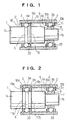
- the compound shaft/bearing apparatus of the first embodiment includes a stepped shaft 1 having an enlarged diameter shaft portion 1a and a reduced diameter shaft portion 1b, a cylindrical sleeve outer race 2 surrounding the stepped shaft, and two rows of rotating bodies, such as balls 3, 4, interposed therebetween.
- the balls 3 of the first row (the left row in Fig. 1) are disposed between an outer peripheral rolling recess 5 formed directly around the outer peripheral surface of the enlarged diameter shaft portion 1a of said stepped shaft 1, and a first inner peripheral rolling recess 6a formed directly in the inner peripheral surface of said sleeve outer race 2.
- the balls 4 of the second row (the right row in Fig. 1) are disposed between an outer peripheral rolling recess 8 provided around the outer peripheral surface of an inner race 7 fitted over the reduced diameter shaft portion 2a of said stepped shaft 1, and a second inner peripheral rolling recess 6b formed directly in the inner peripheral surface of the sleeve outer race 2.
- the outer diameter of said inner race 7 is substantially identical with that of the enlarged diameter shaft portion 1a, so that balls of the same diameter can be employed as the balls 3, 4 of the first and second rows.
- the inner race 7 may be attached to the shaft to leave a space 9 between an inner end of the inner race and a surface of a shoulder formed between the enlarged portion and reduced portion of the shaft.
- a first longitudinally outer sealing plate 10 is provided to seal the clearance defined between the enlarged diameter shaft portion 1a and the sleeve outer race 2.
- a second longitudinally outer sealing plate 11 is provided to seal the clearance defined between the inner race 7 and the sleeve outer race 2.
- the outer sealing plates 10, 11 are ring shaped and have a central aperture therethrough. The outer peripheries of the outer sealing plates 10, 11 are adapted to be fitted into inner peripheral grooves 12a, 12b formed in the inner peripheral surface of said sleeve outer race 2.
- the inner diameter of the central aperture of the outer sealing plate 10 is slightly larger than the outer diameter of the enlarged diameter shaft portion 1a to leave a slight clearance therebetween to provide a labyrinth seal function.
- the inner diameter of the central aperture of the outer sealing plate 11 is slightly larger than the outer diameter of the inner race 7 to leave a slight clearance therebetween to provide a labyrinth seal function.
- the compound shaft/bearing apparatus further includes first and second longitudinally inner sealing plates 13, 14.
- the first inner sealing plate 13 is disposed to the right of the first row of balls 3, and the second inner sealing plate 14 is disposed to the left of the second row of balls 4.
- inner sealing plates 13, 14 are also ring shaped, and have a central aperture therethrough.
- the outer peripheries of the inner sealing plates 13, 14 are fitted into inner peripheral grooves 15a, 15b formed in the inner peripheral surface of said sleeve outer race 2.
- An outer peripheral labyrinth recess 16 is formed around the enlarged diameter shaft portion 1a at the position where the radial plane defined by the first inner sealing plate 13 intersects the shaft 1.
- the inner diameter of the inner sealing plate 13 is substantially equal to or slightly larger than the outer diameter of the enlarged diameter shaft portion 1a to prevent the first inner sealing plate from contacting the shaft, and to provide a labyrinth seal function with the labyrinth recess 16.
- enhancement of the labyrinth seal function can be obtained by the reduction of the inner diameter of the aperture to a diameter slightly smaller than the outer diameter of the enlarged diameter shaft portion 1a.
- the inner periphery of the second inner sealing plate 14 is disposed opposite a space 9 defined between the inner end of the inner race 7 and the surface of the shoulder.
- the inner diameter of the inner sealing plate 14 is substantially equal to or slightly larger than the outer diameter of the enlarged diameter shaft portion 1a to prevent the inner sealing plate from contacting the inner race or the shaft, and to provide a labyrinth seal function.
- enhancement of the labyrinth seal function can be obtained by the reduction of the inner diameter of the aperture to a diameter slightly smaller than the outer diameter of the inner race 7.
- reference numeral 20 The elements represented by reference numeral 20 are ball retainers.
- the outer peripheries of the inner sealing plates 13 and 14 are fitted into the inner peripheral grooves 15a, 15b of the sleeve outer race 2, the stepped shaft 1 is inserted into the sleeve outer race 2, and then inner race 7 is fitted slidably around the reduced diameter shaft portion 1b of the stepped shaft.
- the stepped shaft 1 is displaced radially within the sleeve outer race to form a gap greater than the diameter of balls 3, 4 therebetween, and then these balls are loaded therethrough.
- the inner sealing plate 13 secured on the longitudinally inner side of balls 3 of the first row is adapted to enter the outer peripheral labyrinth groove 16
- the inner sealing plate 14 secured on the longitudinally inner side of balls 4 of the second row is adapted to enter the space 9 defined between inner end of the inner race 7 and the surface of the shoulder, so that the second inner sealing plates do not interfere with the radial displacement of the stepped shaft, and the loading of the balls 3, 4 can be effected easily.
- the balls After loading a predetermined number of balls, the balls are located equidistantly relative to each other by means of ball retainers 20, and then the inner race 7 is bonded or otherwise secured to the reduced diameter shaft portion under a predetermined pressure, and outer sealing plates 10, 11 are also fitted into the inner peripheral grooves 12a, 12b of the sleeve outer race and secured thereto.
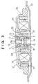
- the inner and outer sealing plates disposed on the opposite side of balls 3 of the first row are mounted in the inner peripheral surface of the sleeve outer race 2 in the embodiment of Fig. 1, the inner and outer sealing plates can alternatively be mounted in the enlarged diameter shaft portion 1a as shown in Fig. 2.
- a pair of outer peripheral grooves 17a, 17b are formed distally and proximally to the outer peripheral rolling recess 5 formed in the enlarged diameter shaft portion 1a.
- Inner peripheral labyrinth grooves 18a, 18b are formed in the portions of the inner peripheral surface of the sleeve outer race 2 intersected by the radial planes including the outer peripheral grooves.
- Outer and inner sealing plates 19a, 19b including a central aperture are respectively fitted at their inner peripheries into the outer peripheral grooves 17a, 17b.
- the outer diameter of the sealing plates 19a, 19b is substantially equal to or slightly smaller than the inner diameter of the sleeve outer race 2 to prevent the inner sealing plates from contacting the sleeve outer race to provide the labyrinth seal function.
- outer and inner sealing plates 19a, 19b be formed with or from pliable material, such as synthetic rubber, enhancement of the labyrinth seal function can be obtained by enlarging the outer diameter of the sealing plates to a diameter slightly larger than the inner diameter of the sleeve outer race 2.
- the assembling operation of the compound shaft/bearing apparatus of the above mentioned second embodiment is adapted to be carried out as follows.
- the inner periphery of the inner sealing plate 19b is fitted into the outer peripheral groove 17b formed in the enlarged diameter shaft portion 1a inwardly of the outer peripheral rolling recess 5, and the outer periphery of the inner sealing plate 14 is fitted into the inner peripheral groove 15b of the sleeve outer race 2. Then the stepped shaft 1 is inserted with the first inner sealing plate into the sleeve outer race 2, and the inner race 7 is fitted slidably around the reduced diameter shaft portion 1b of the stepped shaft.
- the stepped shaft 1 is displaced radially within the sleeve outer race to form a gap greater than the diameter of balls 3, 4 therebetween, and then these balls are loaded therethrough into the inner and outer rolling recess.
- the inner sealing plate 19b secured on the longitudinally inner side of balls 3 of the first row is adapted to enter into the inner peripheral labyrinth groove 18b
- the inner sealing plate 14 secured on the longitudinally inner side of balls 4 of the second row is adapted to enter into the space 9 defined between inner end surface of the inner race 7 and the surface of the shoulder, so that the inner sealing plates do not interfere with the radial displacement of the stepped shaft, and the loading of the balls 3, 4 can be effected easily.
- the balls After loading the predetermined number of balls, the balls are located equidistantly relative to each other by means of ball retainers 20. Then, the inner race 7 is bonded or otherwise fixed to the reduced diameter shaft portion under a predetermined pressure, outer sealing plate 19a is fitted into the outer peripheral groove 17a of the enlarged shaft portion 1a, and the outer sealing plate 11 is fitted into the inner peripheral groove 12b of the sleeve outer race 2 and secured thereto.
- rollers could alternatively be employed to accomplish the same function.
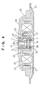
- a compound shaft/bearing apparatus 23 is secured centrally on a base 21 to extend vertically therefrom with the enlarged diameter shaft portion of the bearing being located at the bottom end thereof.
- the base 21 is provided with a flange 22 at the outer periphery thereof.
- a rotor hub 24, i.e. a rotating member of the motor, includes on its central lower surface a cylindrical central portion 25 having upper and lower openings. The cylindrical portion is formed integrally with the rotor hub using the same member.
- the cylindrical portion 25 is fitted over the sleeve outer race 2 of the compound shaft/bearing apparatus 23.
- the rotor hub 24 is provided around the outer periphery thereof with a downwardly depending flange 26 having a disk mount portion for the disk or disks of the hard disk drive device.
- the inner peripheral surface of the downwardly depending flange is provided with rotor magnets 27 made of permanent magnets.
- Stators 30 having respective coils 29 wound therearound are secured around a yoke holder 28 formed integrally with the base to extend upwardly therefrom so as to leave a slight clearance between the outer peripheral portion the stators and the inner peripheral surface of the rotor magnets 27.
- the rotor hub is adapted to be rotatably driven by energizing the coils 29.
- the compound shaft/bearing apparatus 23 is press fitted and adhesively secured within the central cylindrical portion of the rotor hub 24.
- the base or lower end of the enlarged diameter shaft portion 1a of the stepped shaft 1 of the compound bearing apparatus is press fitted and adhesively secured within the bore of the base 21.
- the stepped shaft 1 of the compound shaft/bearing apparatus is adapted to be secured to the base 21 so that the sleeve outer race 2 is adapted to be rotated together with the rotor hub 24, i.e. the spindle motor is of the fixed shaft type.
- a spindle motor of the rotating shaft type may also incorporate the compound bearing apparatus.
- the sleeve 2 is secured to the base 21 and the stepped shaft 1 is adapted to be rotated together with the rotor hub 24.
- the compound shaft/bearing apparatus of the first embodiment shown in Fig. 1 is embodied in the spindle motor
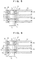
- the compound shaft/bearing apparatus 23' in accordance with the second embodiment as shown in Fig. 2 can also be used as shown in Fig. 4.
- FIG.5 A swing arm assembly for a hard disk drive device is illustrated in Fig.5.
- This swing arm assembly includes the compound shaft/bearing apparatus of the above-mentioned first embodiment.
- a base or a cylindrical portion 34 of a swing arm 33 is secured to the sleeve outer race 32 of the compound bearing apparatus 31.
- the swing arm 33 has mounts 35 for carrying the magnetic head of the hard disk drive device at its distal portion.
- the compound shaft/bearing apparatus 31 is press fitted and adhesively secured within the bore 36 of the cylindrical portion 34 with interposing adhesive between the outer peripheral surface of the sleeve outer race 2 and the inner peripheral surface of the bore of the hub 34.
- magnetic heads are adapted to be attached to the mounts 35, and the lower end of the enlarged diameter shaft portion 1a of the compound shaft/bearing apparatus 31 is secured on the base (not shown) of the hard disk drive device.
- the swing arm assembly can be rotated around the shaft by means of any appropriate actuator.
- the above-described swing arm assembly is of the fixed shaft type in which the cylindrical portion 34 of the swing arm is secured around the sleeve outer race of the compound shaft/bearing apparatus and the stepped shaft is secured to the base of hard disk drive device.
- a swing arm assembly of the rotating shaft type may also incorporate the compound shaft/bearing apparatus.
- the cylindrical portion 34 is secured to the stepped shaft, and the sleeve outer race is secured to the base of hard disk drive device.
- the compound shaft/bearing apparatus as shown in Fig. 1 is employed.
- a compound shaft/bearing apparatus as shown in Fig. 2 may be employed
- the compound shaft/bearing apparatus embodying the present invention includes sealing plates at the longitudinally inner sides of each row of rotating bodies as well as at the longitudinally outer sides, so that the lubricant present around the rotating bodies, the rolling recesses, and the retainers, will be prevented from leaking out from the shaft/bearing apparatus.
- a compound shaft/bearing apparatus which is quiet in operation and has a long life can be obtained.
- the labyrinth seal structure formed by the elements of the shaft/bearing apparatus such as the longitudinally inner and outer sealing plates, the sleeve outer race, and the shaft, does not produce frictional heat and does not affect the rotational torque, since there is no contact between the elements.
- the spindle motor incorporating the compound shaft/bearing apparatus also has a long life and maintains high rotational precision for a long period of time.
- the assembling procedure of the spindle motor can be effected easily merely by press fitting the compound shaft/bearing apparatus into the central cylindrical portion of the rotor hub and securing it thereto, for example by means of adhesive.
- the swing arm assembly incorporating the compound shaft/bearing apparatus also has a long life and maintains high rotational precision for a long period of time, so that the reliability of a hard disk drive device can be enhanced.
- the assembling procedure of the swing arm assembly can be effected easily merely by press fitting the compound shaft/bearing apparatus into the cylindrical portion of the base of the swing arm and securing it thereto by means of adhesive.
Landscapes
- Engineering & Computer Science (AREA)
- General Engineering & Computer Science (AREA)
- Mechanical Engineering (AREA)
- Power Engineering (AREA)
- Rolling Contact Bearings (AREA)
Claims (5)
- Dispositif combiné d'arbre/palier comprenant un arbre à étagement (1) présentant des parties d'arbre à diamètre agrandi (1a) et réduit (1b), une bague extérieure en manchon (2) entourant l'arbre à étagement, et deux séries (3, 4) de corps rotatifs intercalés entre ceux-ci, où :caractérisé en ce que du côté longitudinal intérieur des corps rotatifs (3) de la première série, une première plaque intérieure d'étanchéité (13) en forme de couronne comportant une ouverture centrale est disposée entre la surface périphérique intérieure de la bague extérieure en manchon (2) et la surface périphérique extérieure de la partie d'arbre à diamètre agrandi (la),les corps rotatifs (3) de la première série sont disposés entre un évidement de roulement périphérique extérieur (5) formé directement dans une surface périphérique extérieure de la partie d'arbre à diamètre agrandi (1a) et un premier évidement de roulement périphérique intérieur (6a) formé directement dans la surface périphérique intérieure de la bague extérieure en manchon (2),les corps rotatifs (4) de la seconde série sont disposés entre un évidement de roulement périphérique extérieur (8) formé dans une périphérie extérieure d'une bague intérieure (7) montée sur la partie d'arbre à diamètre réduit (1b) dudit arbre à étagement, et un second évidement de roulement périphérique intérieur (6b) formé directement dans la surface périphérique intérieure de la bague extérieure en manchon (2),du côté longitudinal extérieur des corps rotatifs de la première série, une première plaque extérieure d'étanchéité (10) en forme de couronne comportant une ouverture centrale est disposée entre la surface périphérique intérieure de la bague extérieure en manchon (2) et la surface périphérique extérieure de la partie d'arbre à diamètre agrandi (1a),la première plaque d'étanchéité extérieure (10) est fixée sur l'une de la surface périphérique intérieure de la bague extérieure en manchon (2) et de la surface périphérique extérieure de la partie d'arbre à diamètre agrandi (1a), avec un léger jeu radial entre la surface périphérique intérieure ou extérieure de la première plaque d'étanchéité extérieure (10) et l'autre de la surface périphérique extérieure de la partie d'arbre à diamètre agrandi (1a) et de la surface périphérique intérieure de la bague extérieure en manchon (2), pour agir comme un joint à labyrinthe,au niveau du côté longitudinal extérieur des corps rotatifs (4) de la seconde série, une seconde plaque extérieure d'étanchéité (11) en forme de couronne comportant une ouverture centrale est disposée entre la surface périphérique intérieure de la bague extérieure en manchon (2) et la surface périphérique extérieure de la bague intérieure (7),la seconde plaque d'étanchéité extérieure (11) est fixée à l'une de la surface périphérique intérieure de la bague extérieure en manchon (2) et de la surface périphérique extérieure de la bague intérieure (7), avec un léger jeu radial entre la surface périphérique intérieure ou extérieure de la seconde plaque d'étanchéité extérieure (11) et l'autre de la surface périphérique extérieure de la bague intérieure (7) et de la surface périphérique intérieure de la bague extérieure en manchon (2), pour agir comme un joint à labyrinthe,
la première plaque d'étanchéité intérieure (13) est fixée à l'une de la surface périphérique intérieure de la bague extérieure en manchon (2) et de la surface périphérique extérieure de la partie d'arbre à diamètre agrandi (1a), avec un léger jeu radial entre la surface périphérique intérieure ou extérieure de la première plaque d'étanchéité intérieure (13) et l'autre de la surface périphérique extérieure de la partie d'arbre à diamètre agrandi (la) et de la surface périphérique intérieure de la bague extérieure en manchon (2) pour agir comme un joint à labyrinthe,
du côté longitudinal intérieur des corps rotatifs (4) de la seconde série, une seconde plaque intérieure d'étanchéité (14) en forme de couronne comportant une ouverture centrale est disposée entre la surface périphérique intérieure de la bague extérieure en manchon (2) et la surface périphérique extérieure de la bague intérieure (7), et
la seconde plaque d'étanchéité intérieure (14) est fixée à l'une de la surface périphérique intérieure de la bague extérieure en manchon (2) et de la surface périphérique extérieure de la bague intérieure (7), avec un léger jeu radial entre la surface périphérique intérieure ou extérieure de la seconde plaque d'étanchéité intérieure (14) et l'autre de la surface périphérique extérieure de la bague intérieure (7) et de la surface périphérique intérieure de la bague extérieure en manchon (2), pour agir comme un joint à labyrinthe. - Dispositif selon la revendication 1, dans lequel :les première et seconde plaques d'étanchéité extérieure et intérieure (10, 13, 11, 14) sont montées au niveau de leurs périphéries extérieures dans des rainures périphériques intérieures associées (12, 15a, 12b, 15b) formées dans la surface périphérique intérieure de la bague extérieure en manchon (2),un léger jeu radial est prévu entre les surfaces périphériques intérieures de ladite première plaque d'étanchéité extérieure (10) et la partie d'arbre à diamètre agrandi (1a), pour agir comme un joint à labyrinthe,un léger jeu radial est prévu entre la surface périphérique intérieure de la seconde plaque d'étanchéité extérieure (11) et la bague intérieure (7), pour agir comme un joint à labyrinthe,un léger jeu radial est prévu entre la surface périphérique intérieure de la première plaque d'étanchéité intérieure (13) et un évidement de labyrinthe périphérique extérieur (16) formé dans la surface périphérique extérieure de la partie d'arbre à diamètre agrandi (1a), du côté longitudinal intérieur des corps rotatifs (3) de la première série, pour agir comme un joint à labyrinthe, etun léger jeu radial est prévu entre la surface périphérique intérieure de la seconde plaque d'étanchéité intérieure (14) et un espace (9) défini entre un épaulement formé au niveau de la jonction entre la partie d'arbre à diamètre agrandi (la) et la partie d'arbre à diamètre réduit (1b) et l'extrémité intérieure de la bague intérieure (7), pour agir comme un joint à labyrinthe.
- Dispositif selon la revendication 1, dans lequel :les premières plaques d'étanchéité extérieure et intérieure (10, 13) sont montées au niveau de leurs périphéries intérieures dans une paire de rainures périphériques (17a, 17b) formées de chaque côté de l'évidement de roulement périphérique (5) de la première série (3) de corps rotatifs, dans la surface périphérique extérieure de la partie d'arbre à diamètre agrandi (1a), opposées à une paire de rainures périphériques extérieure et intérieure (18a, 18b) formées sur chaque côté du premier évidement de roulement périphérique intérieur (6a) dans la bague extérieure en manchon (2), respectivement, avec un léger jeu radial entre la surface périphérique extérieure de chaque plaque d'étanchéité (10, 13) et chaque rainure périphérique (18a, 18b), pour agir comme un joint à labyrinthe,les secondes plaques d'étanchéité extérieure et intérieure (11, 14) sont montées de façon fixe au niveau de leurs périphéries extérieures dans une paire de rainures périphériques (12b, 15b) formées sur chaque côté du second évidement de roulement périphérique intérieur (6b) formé dans la surface périphérique intérieure de la bague extérieure en manchon (2), avec un léger jeu radial entre la surface périphérique intérieure de la plaque d'étanchéité extérieure (11) et la bague intérieure (7), pour agir comme un joint à labyrinthe, et avec un léger jeu radial entre la surface périphérique intérieure de la plaque d'étanchéité intérieure (14) et un espace (9) défini entre un épaulement formé au niveau de la jonction de la partie d'arbre à diamètre agrandi (1a) et de la partie d'arbre à diamètre réduit (1b) et une extrémité intérieure de la bague intérieure (7), pour agir comme un joint à labyrinthe.
- Moteur axial comprenant un élément rotatif (24), tel qu'un moyeu de rotor, tourillonné sur une base (21) au moyen d'un dispositif combiné d'arbre/palier (23, 23') selon la revendication 1, 2 ou 3.
- Ensemble de bras oscillant tourillonné avec possibilité de rotation sur une base d'un dispositif de lecteur de disque dur par l'intermédiaire d'un dispositif combiné d'arbre/palier (31) selon la revendication 1, 2 ou 3, ledit dispositif combiné d'arbre/palier étant situé à l'intérieur d'une partie cylindrique de base (34) de l'ensemble de bras oscillant.
Applications Claiming Priority (2)
| Application Number | Priority Date | Filing Date | Title |
|---|---|---|---|
| JP24220998A JP2000074052A (ja) | 1998-08-27 | 1998-08-27 | 複合軸受装置および同軸受装置を備えるスピンドルモータならびにハードディスクドライブ装置用スイングアームアセンブリ |
| JP24220998 | 1998-08-27 |
Publications (3)
| Publication Number | Publication Date |
|---|---|
| EP0982508A2 EP0982508A2 (fr) | 2000-03-01 |
| EP0982508A3 EP0982508A3 (fr) | 2001-03-21 |
| EP0982508B1 true EP0982508B1 (fr) | 2004-07-28 |
Family
ID=17085882
Family Applications (1)
| Application Number | Title | Priority Date | Filing Date |
|---|---|---|---|
| EP19990306831 Expired - Lifetime EP0982508B1 (fr) | 1998-08-27 | 1999-08-27 | Arbre/palier composé et moteur de broche et bras pivotant pour un entraínement de disque dur comportant un tel palier |
Country Status (3)
| Country | Link |
|---|---|
| EP (1) | EP0982508B1 (fr) |
| JP (1) | JP2000074052A (fr) |
| DE (1) | DE69918913T2 (fr) |
Cited By (1)
| Publication number | Priority date | Publication date | Assignee | Title |
|---|---|---|---|---|
| US9945420B2 (en) | 2013-03-14 | 2018-04-17 | Koyo Bearings North America Llc | Bearing assembly for steering column |
Families Citing this family (10)
| Publication number | Priority date | Publication date | Assignee | Title |
|---|---|---|---|---|
| JPH11328835A (ja) * | 1998-05-14 | 1999-11-30 | Minebea Co Ltd | モータおよび同モータを備えるハードディスクドライブ装置 |
| JP2001309606A (ja) * | 2000-04-19 | 2001-11-02 | Minebea Co Ltd | Oa機器用の複合軸受電動機 |
| US7384198B2 (en) * | 2000-08-09 | 2008-06-10 | Nsk Ltd. | Rolling bearing |
| US7195191B2 (en) * | 2002-12-30 | 2007-03-27 | Samsung Electronics Co., Ltd. | Oil spattering prevention apparatus for tape recorder |
| JP2005276291A (ja) * | 2004-03-24 | 2005-10-06 | Hitachi Global Storage Technologies Netherlands Bv | 回転円板形記憶装置及びピボット軸受アセンブリ |
| CN102562821A (zh) * | 2012-02-29 | 2012-07-11 | 杨丽萍 | 一种轴承外圈内侧的分瓣组合式挡圈 |
| JP6080645B2 (ja) * | 2013-03-27 | 2017-02-15 | 荏原冷熱システム株式会社 | ターボ冷凍機の圧縮機用電動機 |
| JP5883061B2 (ja) | 2014-04-22 | 2016-03-09 | ファナック株式会社 | 軸受部品の飛散防止部材を備える電動機 |
| DE102014224957B3 (de) * | 2014-12-05 | 2015-11-26 | Schaeffler Technologies AG & Co. KG | Spindelelement für einen Kugelgewindetrieb |
| CN108267069B (zh) * | 2016-12-30 | 2023-09-08 | 江苏核电有限公司 | 一种汽轮机发电机组悬轴摆度测量工具及方法 |
Family Cites Families (3)
| Publication number | Priority date | Publication date | Assignee | Title |
|---|---|---|---|---|
| US5547291A (en) * | 1993-09-29 | 1996-08-20 | Nsk, Ltd. | Preloaded rolling bearing units |
| US5588753A (en) * | 1994-08-17 | 1996-12-31 | Kabushiki Kaisha Sankyo Seiki Seisakusho | Disk drive motor with labyrinth seal |
| US5800069A (en) * | 1995-07-07 | 1998-09-01 | Obara; Rikuro | Compound bearing assembly |
-
1998
- 1998-08-27 JP JP24220998A patent/JP2000074052A/ja not_active Withdrawn
-
1999
- 1999-08-27 DE DE1999618913 patent/DE69918913T2/de not_active Expired - Lifetime
- 1999-08-27 EP EP19990306831 patent/EP0982508B1/fr not_active Expired - Lifetime
Cited By (1)
| Publication number | Priority date | Publication date | Assignee | Title |
|---|---|---|---|---|
| US9945420B2 (en) | 2013-03-14 | 2018-04-17 | Koyo Bearings North America Llc | Bearing assembly for steering column |
Also Published As
| Publication number | Publication date |
|---|---|
| DE69918913D1 (de) | 2004-09-02 |
| DE69918913T2 (de) | 2005-07-14 |
| JP2000074052A (ja) | 2000-03-07 |
| EP0982508A3 (fr) | 2001-03-21 |
| EP0982508A2 (fr) | 2000-03-01 |
Similar Documents
| Publication | Publication Date | Title |
|---|---|---|
| US5214326A (en) | Spindle motor with magnetic shield for magnetic fluid seal | |
| US7466050B2 (en) | Brushless motor and method of manufacturing the same | |
| JP5160778B2 (ja) | 多機能構成要素を備えたモータ組立体 | |
| US6545378B2 (en) | Electric spindle motor with magnetic bearing and hydrodynamic bearing | |
| EP0982508B1 (fr) | Arbre/palier composé et moteur de broche et bras pivotant pour un entraínement de disque dur comportant un tel palier | |
| US6538354B2 (en) | Spindle motor with toroidal sealing plates | |
| US20030201683A1 (en) | Electric spindle motor and method having magnetic starting/stopping device | |
| US20100239194A1 (en) | Disk drive device improved in handling property | |
| US6102575A (en) | Compound bearing apparatus | |
| US6181513B1 (en) | Spindle motor and a hard disk drive apparatus including such a motor | |
| US6582129B2 (en) | Compound bearing apparatus, and spindle motor and swing arm for hard disk drive means including such bearing apparatus | |
| JP2006353058A (ja) | スピンドルモータおよび該スピンドルモータを搭載した記録ディスク駆動装置 | |
| JP2623873B2 (ja) | ポリゴンスキヤナモータ及びその製造方法 | |
| JP3234030B2 (ja) | スピンドルモータ | |
| EP1134875A1 (fr) | Moteur d'entraínement d'axe pour appareil d'entraínement de disque avec palier à fluide | |
| JP3386965B2 (ja) | スピンドルモータの軸受構造 | |
| JP3392212B2 (ja) | 多孔質含油軸受ユニット及びこれを備えたモータ並びに多孔質含油軸受ユニットの製造方法 | |
| JPH102329A (ja) | 軸受装置 | |
| JPH10146007A (ja) | ディスク駆動用スピンドルモータ | |
| JP3092642B2 (ja) | 磁気ディスク装置 | |
| JPH09329138A (ja) | 複合軸受け及びスピンドルモータ | |
| JPS6069320A (ja) | ベアリング付きシヤフト・ユニット | |
| JP2661996B2 (ja) | 磁気テープ記録再生装置のドラムユニット及び軸付軸受 | |
| JP2562870Y2 (ja) | アウタロ−タ型モ−タ | |
| JPS6120216A (ja) | 回転ヘツドアセンブリ |
Legal Events
| Date | Code | Title | Description |
|---|---|---|---|
| PUAI | Public reference made under article 153(3) epc to a published international application that has entered the european phase |
Free format text: ORIGINAL CODE: 0009012 |
|
| AK | Designated contracting states |
Kind code of ref document: A2 Designated state(s): DE GB |
|
| AX | Request for extension of the european patent |
Free format text: AL;LT;LV;MK;RO;SI |
|
| PUAL | Search report despatched |
Free format text: ORIGINAL CODE: 0009013 |
|
| AK | Designated contracting states |
Kind code of ref document: A3 Designated state(s): AT BE CH CY DE DK ES FI FR GB GR IE IT LI LU MC NL PT SE |
|
| AX | Request for extension of the european patent |
Free format text: AL;LT;LV;MK;RO;SI |
|
| 17P | Request for examination filed |
Effective date: 20010831 |
|
| AKX | Designation fees paid |
Free format text: DE GB |
|
| GRAP | Despatch of communication of intention to grant a patent |
Free format text: ORIGINAL CODE: EPIDOSNIGR1 |
|
| RTI1 | Title (correction) |
Free format text: A COMPOUND SHAFT/BEARING APPARATUS, AND A SPINDLE MOTOR AND A SWING ARM FOR A HARD DISK DRIVE MEANS INCLUDING SUCH BEARIN |
|
| GRAS | Grant fee paid |
Free format text: ORIGINAL CODE: EPIDOSNIGR3 |
|
| GRAA | (expected) grant |
Free format text: ORIGINAL CODE: 0009210 |
|
| AK | Designated contracting states |
Kind code of ref document: B1 Designated state(s): DE GB |
|
| REG | Reference to a national code |
Ref country code: GB Ref legal event code: FG4D |
|
| REF | Corresponds to: |
Ref document number: 69918913 Country of ref document: DE Date of ref document: 20040902 Kind code of ref document: P |
|
| PLBE | No opposition filed within time limit |
Free format text: ORIGINAL CODE: 0009261 |
|
| STAA | Information on the status of an ep patent application or granted ep patent |
Free format text: STATUS: NO OPPOSITION FILED WITHIN TIME LIMIT |
|
| 26N | No opposition filed |
Effective date: 20050429 |
|
| PGFP | Annual fee paid to national office [announced via postgrant information from national office to epo] |
Ref country code: GB Payment date: 20080903 Year of fee payment: 10 |
|
| PGFP | Annual fee paid to national office [announced via postgrant information from national office to epo] |
Ref country code: DE Payment date: 20090821 Year of fee payment: 11 |
|
| GBPC | Gb: european patent ceased through non-payment of renewal fee |
Effective date: 20090827 |
|
| PG25 | Lapsed in a contracting state [announced via postgrant information from national office to epo] |
Ref country code: GB Free format text: LAPSE BECAUSE OF NON-PAYMENT OF DUE FEES Effective date: 20090827 |
|
| REG | Reference to a national code |
Ref country code: DE Ref legal event code: R119 Ref document number: 69918913 Country of ref document: DE Effective date: 20110301 |
|
| PG25 | Lapsed in a contracting state [announced via postgrant information from national office to epo] |
Ref country code: DE Free format text: LAPSE BECAUSE OF NON-PAYMENT OF DUE FEES Effective date: 20110301 |