EP0981836B1 - Verfahren und vorrichtung zur antennenkalibrierung - Google Patents
Verfahren und vorrichtung zur antennenkalibrierung Download PDFInfo
- Publication number
- EP0981836B1 EP0981836B1 EP98922006A EP98922006A EP0981836B1 EP 0981836 B1 EP0981836 B1 EP 0981836B1 EP 98922006 A EP98922006 A EP 98922006A EP 98922006 A EP98922006 A EP 98922006A EP 0981836 B1 EP0981836 B1 EP 0981836B1
- Authority
- EP
- European Patent Office
- Prior art keywords
- com
- module
- reception
- antenna
- complex
- Prior art date
- Legal status (The legal status is an assumption and is not a legal conclusion. Google has not performed a legal analysis and makes no representation as to the accuracy of the status listed.)
- Expired - Lifetime
Links
Images


Classifications
-
- G—PHYSICS
- G01—MEASURING; TESTING
- G01S—RADIO DIRECTION-FINDING; RADIO NAVIGATION; DETERMINING DISTANCE OR VELOCITY BY USE OF RADIO WAVES; LOCATING OR PRESENCE-DETECTING BY USE OF THE REFLECTION OR RERADIATION OF RADIO WAVES; ANALOGOUS ARRANGEMENTS USING OTHER WAVES
- G01S7/00—Details of systems according to groups G01S13/00, G01S15/00, G01S17/00
- G01S7/02—Details of systems according to groups G01S13/00, G01S15/00, G01S17/00 of systems according to group G01S13/00
- G01S7/40—Means for monitoring or calibrating
- G01S7/4004—Means for monitoring or calibrating of parts of a radar system
- G01S7/4026—Antenna boresight
-
- H—ELECTRICITY
- H01—ELECTRIC ELEMENTS
- H01Q—ANTENNAS, i.e. RADIO AERIALS
- H01Q3/00—Arrangements for changing or varying the orientation or the shape of the directional pattern of the waves radiated from an antenna or antenna system
- H01Q3/26—Arrangements for changing or varying the orientation or the shape of the directional pattern of the waves radiated from an antenna or antenna system varying the relative phase or relative amplitude of energisation between two or more active radiating elements; varying the distribution of energy across a radiating aperture
- H01Q3/267—Phased-array testing or checking devices
-
- G—PHYSICS
- G01—MEASURING; TESTING
- G01S—RADIO DIRECTION-FINDING; RADIO NAVIGATION; DETERMINING DISTANCE OR VELOCITY BY USE OF RADIO WAVES; LOCATING OR PRESENCE-DETECTING BY USE OF THE REFLECTION OR RERADIATION OF RADIO WAVES; ANALOGOUS ARRANGEMENTS USING OTHER WAVES
- G01S13/00—Systems using the reflection or reradiation of radio waves, e.g. radar systems; Analogous systems using reflection or reradiation of waves whose nature or wavelength is irrelevant or unspecified
- G01S13/02—Systems using reflection of radio waves, e.g. primary radar systems; Analogous systems
- G01S2013/0236—Special technical features
- G01S2013/0245—Radar with phased array antenna
-
- G—PHYSICS
- G01—MEASURING; TESTING
- G01S—RADIO DIRECTION-FINDING; RADIO NAVIGATION; DETERMINING DISTANCE OR VELOCITY BY USE OF RADIO WAVES; LOCATING OR PRESENCE-DETECTING BY USE OF THE REFLECTION OR RERADIATION OF RADIO WAVES; ANALOGOUS ARRANGEMENTS USING OTHER WAVES
- G01S7/00—Details of systems according to groups G01S13/00, G01S15/00, G01S17/00
- G01S7/02—Details of systems according to groups G01S13/00, G01S15/00, G01S17/00 of systems according to group G01S13/00
- G01S7/40—Means for monitoring or calibrating
- G01S7/4052—Means for monitoring or calibrating by simulation of echoes
- G01S7/406—Means for monitoring or calibrating by simulation of echoes using internally generated reference signals, e.g. via delay line, via RF or IF signal injection or via integrated reference reflector or transponder
Definitions
- the present invention is related to devices and methods for antenna calibration.
- the invention is related to calibration of antenna systems comprising electrically controlled antennas.
- Many technical applications comprise some form of antenna function, in which signals are to be received or transmitted through air. Examples of such applications are radios, television sets, mobile telephony systems and radar systems.
- a radio is to be able to receive signals from different radio stations independently of where it has been placed, and the antenna should therefore preferably be equally sensitive in all directions in the horizontal plane.
- a television set on the other hand, should only be sensitive to signals coming from the nearest television mast.
- the antenna of a television set should therefore be arranged in such a way that it is particularly sensitive to signals coming from a particular direction, and signals coming from other directions should be suppressed to the greatest degree possible.
- a radar is usually to both transmit and receive in a certain direction, and it should also be possible to change this direction so that the radar can obtain information about the surroundings in different directions. For radar also it is desirable that the antenna suppress signals from other directions than the direction in which the radar is currently transmitting and receiving.
- One type of antenna having a directional function is the so-called reflector antenna.
- a reflector antenna comprises a conducting reflector, positioned behind the antenna element itself.
- the dimensions of the reflector should be considerably greater than the wave-length of the signals used for the application concerned.
- the reflector is shaped in such a way that it superimposes signals incoming in a certain direction.
- the sensitivity direction of the antenna can be changed by mechanically redirecting the antenna.
- the most common reflector antenna is probably the dish antenna.
- the reflector of a dish antenna functions as a parabolic mirror, concentrating waves incoming parallel to the main axis of the dish to the focus of the dish. In the focus of the dish the antenna element, usually a horn antenna is placed.
- An electrically controlled antenna comprises a number of modules, usually arranged in a row or in a matrix pattern. The number of modules can vary very much depending on the application concerned. Each module usually comprises one antenna element.
- the signal is divided into a number of sub-signals of equal size, and each sub-signal is fed to one of the modules.
- the modules comprise signal channels guiding the sub-signals to the antenna elements.
- Each signal channel comprises controllable attenuators (alternatively controllable amplifiers) and controllable phase-shifting devices for controlling the amplification and the phase shift of the modules.
- the signals transmitted through the antenna elements interfere with each other.
- the directional sensitivity of the antenna is to be redirected, only the amplification and the phase-shifting of the modules have to be changed.
- the change of the amplification and the phase-shifting can be done electronically so that no mechanical redirection of the antenna has to be carried out.
- each antenna element receives a sub-signal.
- the modules comprise signal channels for reception and through these signal channels the sub-signals are transmitted to an addition point in which all sub-signals are added to form one signal.
- the signal channels for reception also comprise amplifiers and phase shifters, and the directional sensitivity of the antenna for reception can be controlled in a corresponding way as for transmission, by varying the amplification and phase-shifting of the modules.
- T/R modules Transmitter/Receiver modules
- the antenna transmit or receive in a particular direction while signals in other directions are suppressed to as great a degree as possible.
- For transmission it is usually desirable to concentrate the transmitted signal as much as possible and for reception to avoid disturbing signals from the adjacent directions.
- These properties are usually summed up in that the side lobe levels of the antenna are to be as low as possible.
- the amplification and phase shift of the T/R modules are obtained by considering the change in amplitude and phase of the test signal when it passes the T/R module.
- the control signals controlling the attenuators and the phase shifters in the T/R modules can now be corrected so that the amplification and the phase-shifting are made to coincide with the commanded (desired) amplification and phase-shifting.
- the position of the horn relative to the antenna must be known with a high accuracy, in order for the test signals inserted in the T/R modules to have a known amplitude and phase. Also this places strict requirements that no signals be reflected back to the antenna from the surrounding. This is not fulfilled, for example, in an airplane radar in which reflection from radome and other parts of the airplane can occur. It is generally impossible to predict the influence of these reflections and this type of calibration is therefore not suitable, for example, for an airplane radar.
- the method of providing the antenna with an extra calibration network functions well even in, for example, an airplane radar.
- the disadvantage of this solution is the high complexity implied by the distribution network, in particular in the cases when the antenna comprises a large number (thousands) of T/R modules.
- Prior art document EP-A-496 381 shows a phase measuring method for testing a phased array making use of a far field test source which illuminates the antenna. The method involves using different subarray steering bit settings resulting in different phase values of the combined signal. If one subarray steering bit is not functional, then the entire subarray module is replaced.
- Prior art document US-A-5 294 934 shows a phase measuring circuit used for setting a phase or performing a failure diagnosis for each element.
- a test antenna is provided for transmitting or receiving a test signal so as to measure the phase of the phased array antenna, such that a loop is formed between a terminal for a transmitted signal and the terminal for the received signal in the phased array antenna.
- Prior art document US-A-5 530 449 shows s phased array antenna management and calibration method in which a non-interfering probe carrier is processed through each antenna chain of the transmit and receive antennas.
- a local sense antenna is used to to sample outputs of the transmit antenna elements which are fed back to a processor which computes corrective weighting coefficients.
- the present invention relates to solving the problem of calibrating an antenna system comprising an electrically controlled antenna utilizing a test antenna arranged near the electrically controlled antenna, with the possibility of calibration during operation when disturbing reflections or other unknown signal influences are present when signals are transmitted between the test antenna and the electrically controlled antenna or between the electrically controlled antenna and the test antenna.
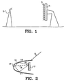
- Figure 1 shows how calibration of an electrically controlled antenna 1 can be carried out according to prior art.
- a test antenna 5 is placed at a remote field distance from the electrically controlled antenna 1. The position of the test antenna 5 relative to the electrically controlled antenna 1 is accurately measured.
- the test antenna 5 and the electrically controlled antenna 1 are positioned in such a way as to minimize the reflections occurring from the surroundings.
- a test signal is transmitted from the test antenna 5 and received through the electrically controlled antenna 1.
- the way in which the test antenna 5 is arranged in Figure 1 makes it possible to determine the phase and the amplitude of the signals inserted into the radiation elements 3 of the electrically controlled antenna 1 relatively accurately. By measuring the phase and the amplitude of the signal received through the electrically controlled antenna 1, it is thus possible to obtain information about the actual phase-shifting and amplification of the modules.
- the actual phase-shifting and amplification are compared to the desired phase-shifting and amplification, and a switching of the control signals to the phase shifters and attenuators of the modules can be performed based on this comparison.
- the configuration shown in Figure 1 can also be used to calibrate the electrically controlled antenna 1 during transmission.
- the test signal is then transmitted from the electrically controlled antenna 1 and received through the test antenna 5; the calibration is in all other respects carried out in a corresponding way as with calibration during reception.
- FIG. 1 In a moving application, such as, for example, a radar in an airplane, the ideal conditions valid for the calibration described in Figure 1 do not exist.
- FIG 2 an attempt to calibrate an electrically controlled antenna 7 in an airplane 9 is shown.
- the electrically controlled antenna 7 is here arranged in a radome 11 in the nose of the airplane 9.
- a test antenna 13 is also arranged in the radome 11.
- the test antenna 13 in Figure 2 is much closer to the electrically controlled antenna 7 than was the case in Figure 1 , which poses stricter requirements on the determination of the position of the test antenna 13 relative to the electrically controlled antenna 7.
- a test signal is transmitted from the test antenna 13 in Figure 2 , reflections causing problems will arise in the radome 11.
- a signal received through any of the radiation elements 21 of the electrically controlled antenna 7 will therefore be combined by a direct signal 15 as well as a number of reflected signals 17 and 19.
- the signals received through the radiation elements 21 are not fully known, which reduces or prevents the calibration ability of the system in Figure 2 .
- this causes the configuration shown in Figure 2 to be unsuitable for a moving application in which calibration is to be carried out during operation. Therefore, more complicated solutions are normally needed for such applications.
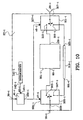
- Figure 3 shows an antenna system 23 in accordance with the present invention.
- the antenna system of Figure 3 can, for example, be conceived to be part of a radar.
- the antenna system in Figure 3 comprises an antenna unit 25, which is an electrically controlled antenna.
- the antenna unit 25 comprises a number of T/R modules 27-(1-N), each in turn comprising radiation elements 29-(1-N), through which signals can be transmitted or received.
- the antenna unit 25 further comprises a distribution unit 31.
- the distribution unit 31 comprises an analogue distribution connection 33 connected to a bidirectional analogue distribution net situated in the distribution unit - not shown in Figure 3 .
- the analogue distribution network connects the analogue distribution connection 33 to analogue signal connections 35-(1-N) in each T/R module 27-(1-N). Signals to be transmitted through the antenna unit 31 are thus fed to the distribution connection 33 and distributed by the analogue distribution network to the analogue signal connec-tions 35-(1-N) of the T/R modules 27-(1-N).
- signals are supplied to the analogue distribution network from the analogue signal connections 35-(1-N) of the T/R modules 27-(1-N), and these signals are added by the analogue distribu-tion network to a sum signal, which is fed to the analogue distribution connection 33.
- the sum signal thus constitutes the signal received through the antenna unit 25.
- the distribution unit 31 also comprises digital distribution connections for digital communication to and from the T/R modules - the digital distribution connections being collectively referred to by reference numeral 37 in Figure 3 .
- the distribution unit 31 comprises a first digital distribution network - not shown in Figure 3 - for digital signal transfer to the T/R modules 27-(1-N).
- the first digital distribution network distributes digital signals from the digital distribution connections 37 to digital input signal connections in the T/R modules 27-(1-N).
- the distribution unit 31 also comprises a second digital distribution network - not shown in Figure 3 - which transfers digital signals from digital output output signal connections in the T/R modules 27-(1-N) to the digital distribution connections 37.
- the digital input signal and output signal connections for each T/R module 27-(1-N) are collectively referred to by reference numeral 39-(1-N) in Figure 3 .
- the antenna system 23 in Figure 3 further comprises a control unit 41 for controlling the antenna system 23.
- the control unit 41 comprises digital input signal and output signal connections, collectively referred to by reference numeral 43 in Figure 3 .
- the digital input signal and output signal connections 43 of the control unit 41 are connected to the digital distribution connections 37.
- Bidirectional digital communication channels are in this way established between the control unit 41 and the T/R modules 27-(1-N).
- the digital communication channels are utilized by the control unit 41 for control and supervision of the work of the T/R modules 27-(1-N).
- FIG 4 shows, by means of an example, a construction of the T/R modules 27-(1-N) of the antenna system 23 in Figure 3 .
- the T/R module in Figure 4 as an example, T/R module No. i 27-i, comprises an analogue signal connection 35-i and a radiation element 29-i.
- the T/R module 27-i in Figure 4 has functions for reception and transmission.
- the analogue signal connection 35-i of the T/R module 27-i in Figure 4 is connected to a signal connection 83-i of a controllable attenuator 81-i.
- the controllable attenuator 81-i is followed by a controllable phase shifter 85-i.
- the controllable attenuator 81-i and the controllable phase shifter 85-i comprises control signal inputs 87-i and 89-i for receiving control signals c3-i and c4-i.
- control signal inputs 87-i and 89-i of the controllable attenuator 81-i and the controllable phase shifter 85-i are connected to a corresponding first set of control signal outputs 93-i of a control unit 91-i belonging to the T/R module 27-i.
- the control unit 91-i is thus arranged to control the controllable attenuator 81-i and the controllable phase shifter 85-i.
- a signal connection 95-i of the controllable phase shifter 85-i is connected to a signal connection 97-i of a first controllable switch 99-i.
- the first controllable switch 99-i can be set to a first position 101-i, whereby the signal connection 97-i of the first controllable switch 99-i is connected to an input 105-i of a first amplifier 103-i.
- the first controllable switch 99-i can also be set to a second position 107-i, whereby the signal connection 97-i of the first controllable switch 99-i is connected to an output 111-i of a second amplifier 109-i.
- the T/R module 27-i in Figure 4 further comprises a second controllable switch 113-i having a signal connection 115-i.
- the second controllable switch 113-i can be set to a first position 117-i, whereby the signal connection 115-i of the second controllable switch 113-i is connected to an output 119-i of the first amplifier 103-i.
- the second controllable switch 113-i can also be set to a second position 121-i, whereby the signal connection 115-i of the second controllable switch 113-i is connected to an input 123-i of the second amplifier 109-i.
- the T/R module 27-i in Figure 4 further comprises a third controllable switch 125-i having a signal connection 127-i.
- the third controllable switch 125-i can be set to a first position 129-i, whereby the signal connection 127-i of the third controllable switch 125-i is connected to the radiation element 29-i of the T/R module 27-i.
- the third controllable switch 125-i can also be set to a second position 131-i, whereby the radiation element 29-i of the T/R module 27-i is isolated in such a way that signals can neither pass to nor from the radiation element 29-i.
- the third controllable switch 125-i When the third controllable switch 125-i is in its second position 131-i, in this description it is said that the T/R module 27-i is in its isolated mode.
- the signal connection 127-i of the third controllable switch 125-i is connected to the signal connection 115-i of the second controllable switch 113-i.
- the three controllable switches 99-i, 113-i and 125-i comprise control signal inputs 133-i, 135-i and 137-i, connected to a corresponding second set of control signal outputs 139-i in the control unit 91-i of the T/R module 27-i.
- the control unit 91-i is in this case arranged to control the positions 101-i, 107-i, 117-i, 121-i, 129-i and 131-i of the three controllable switches 99-i, 113-i and 125-i, and this is done by means of control signals c4-i, c5-i and c6-i.
- a signal channel for transmission can be established by setting the three controllable switches 99-i, 113-i and 125-i to their first positions 101-i, 117-i and 129-i.
- a signal coming into the T/R module 27-i through the analogue signal connection 35-i of the T/R module in such a situation will then be transferred to the radiation element 29-i through the following elements in the order stated: the controllable attenuator 81-i, the controllable phase shifter 85-i, the first controllable switch 99-i, the first amplifier 103-i, the second controllable switch 113-i and the third controllable switch 125-i.
- a signal channel for reception can also be established, by setting the first and the second controllable switch 99-i and 113-i to their second positions 107-i and 121-i, while the third controllable switch 125-i remains in its first position 129-i.
- a signal received through the radiation element 29-i is in such a situation transferred to the analogue signal connection 35-i of the T/R module 27-i through the following elements in the order stated: the third controllable switch 125-i, the second controllable switch 113-i, the second amplifier 123-i, the first controllable switch 99-i, the controllable phase shifter 85-i and the controllable attenuator 81-i.
- the T/R module 27-i in Figure 4 further comprises a thermometer 141-i.
- the thermometer 141-i is arranged to measure the temperature in the T/R module 27-i and emit, through a detector signal output 143-i, a temperature detector signal d2-i corresponding to the measured temperature.
- the detector signal output 143-i of the thermometer 141-i is connected to a corresponding detector signal input 145-i in the control unit 91-i of the T/R module.
- the control unit 91-i in Figure 4 comprises digital input signal and output signal connections 147-i, connected to the digital input signal and output signal connections 39-i of the T/R module.
- the control unit 91-i is thus arranged to be able to communicate with the control unit 41 in Figure 3 .
- phase-shifting and amplification of the different T/R modules 27-(1-N) are to assume specific values.
- the control unit 41 therefore sends commands to each T/R module 27-(1-N) about the phase-shifting and amplification to be applied in a given situation.
- the commanded phase-shifting at transmission and reception, respectively, for T/R module No. 1 27-1 (1 ⁇ 1 ⁇ N) is here denoted by T(1) PHASE COM and R(1) PHASE COM , respectively.
- T(1) AMPLIFICATION COM and R(1) AMPLIFICATION COM denote the commanded amplification for T/R module No. 1 27-1 at transmission and reception, respectively.
- commanded complex amplifications T(1) A COM and R(1) A COM are introduced for T/R module No. 1 27-1 at transmission and reception, respectively, here defined as A COM T / R 1 ⁇ AMPLIFICATION COM T / R 1 ⁇ exp j ⁇ PHASE COM T / R 1
- Amplification and phase-shifting - the complex amplification - in the T/R module 27-i in Figure 4 are controlled by means of the controllable attenuator 81-i and the controllable phase shifter 85-i.
- the T/R module 27-i obtains a certain value of the commanded complex amplification T/R(i) A COM from the control unit 41, it is the task of the control unit 91-i to generate such control signals c3-i and c4-i to the controllable attenuator and the controllable phase shifter that the complex amplification of the T/R module 27-i relative to the other T/R modules corresponds to the actual value of the commanded complex amplification T/R(i) A COM .
- control unit of a T/R module like the T/R module 27-i in Figure 4 it is common in the art for the control unit to comprise memory means holding calibration data.
- the calibration data of the control unit in such a case gives the control unit information about how the control signals to the attenuator and the phase shifter are to be set.
- the complex amplification in a T/R module like the T/R module 27-i in Figure 4 is, however, affected by the temperature and by the carrier frequency currently used by the antenna system. If an antenna system is to control the T/R modules for a number of different values of the commanded complex amplifications T/R(1) A COM (1 ⁇ 1 ⁇ N) and utilize different carrier frequencies at the same time as the antenna system is exposed to temperature changes, a large amount of calibration data is needed in the control unit to enable the exact control of the T/R modules for all the combinations of these variables - commanded complex amplifications T/R(1) A COM , carrier frequencies and temperature - that can arise.
- a self-calibrating system too, it can, however, be optimal to store a certain amount of calibration data; the exact amount of calibration data that is optimally to be stored in a self-calibrating antenna system depends on the application. If, for example, the values of the commanded complex amplifications T/R(1) A COM vary considerably faster than the temperature and the carrier frequencies used by the system vary, it may be suitable to store such an amount of calibration data that adjustments of the control signals to the controllable attenuators and phase shifters are associated to possible values of the commanded complex amplifications T/R(1) A COM . When the temperature or the carrier frequency is changed, the system adjusts the control signals controlling the controllable attenuators and phase shifters, whereby calibration data is modified.
- the values of the commanded complex amplifications T/R(1) A COM and carrier frequency vary faster than the temperature, it may be suitable to store calibration data associating adjustments of control signals to the controllable attenuators and the controllable phase shifters to the combinations of possible values of the commanded complex amplifications T/R(1) A COM and possible carrier frequencies. If the temperature varies faster than the values of the commanded complex amplifications T/R(1) A COM and carrier frequency, it may be the optimal solution to carry out an adjustment of the control signals controlling the controllable attenuators and phase shifters every time a variable is changed.
- Antenna systems that are self-calibrating during operation are, as mentioned above, usually complicated.
- the antenna system 23 in Figure 3 can, however, be calibrated with relatively simple means, which will be described in the following.
- the antenna system 23 in Figure 3 comprises a test antenna 45 having a radiation element 46. Through the test antenna 45, signals may be transmitted or received.
- the test antenna 45 is arranged near the antenna unit 25, so that the signals transmitted through the test antenna 45 can be received through the antenna unit 25 and so that signals transmitted through the antenna unit 25 can be received through the test antenna 45.
- the antenna system 23 in Figure 3 also comprises a signal generator 47.
- the signal generator 47 comprises a controllable oscillator 49 and a signal switch 53.
- the controllable oscillator 49 is connected to the signal switch 53.
- the signal switch 53 can be set to a first and a second position 55 and 57.
- a signal is switched from the controllable oscillator 49 through the signal switch 53 to a first distribution point 59.
- the first distribution point 59 is connected both to the test antenna 45 and to a first signal input 63 in a receiver 61.
- When the signal switch 53 is in its second position 57, a signal is switched from the controllable oscillator 49 through the signal switch 53 to a second distribution point 65.
- the second distribution point 65 is connected both to the analogue distribution connection 33 in the distribution unit 31, and to a second signal input 67 in the receiver 61.
- a signal from the controllable oscillator 49 will be divided into two parts at the first distribution point 59.
- One of the signal parts is received by the receiver 61 through the first signal input 63 of the receiver, and the other signal part is fed to the test antenna 45, so that a signal will be transmitted from the test antenna 45. If the signal transmitted from the test antenna 45 in this way is received by the antenna unit 25, the signal received by the antenna unit 25 will be transferred to the second signal input 63 of the receiver 61.
- a signal from the controllable oscillator 49 will be divided into two parts at the second distribution point 65.
- One signal part is then fed to the second signal input 67 of the receiver, and the other signal part is fed to the analogue distribution connection 33 of the distribution unit 33.
- a signal can then be transmitted through the antenna unit 25.
- the signal transmitted through the antenna unit 25 can be received through the test antenna 45, and the signal received through the test antenna is fed to the first signal input 65 of the receiver 61.
- the signal generator 47 in Figure 3 comprises control signal inputs 69 and 71 for receiving control signals c1 and c2 for control of the controllable oscillator 49 and the signal switch 53.
- the control signal inputs 69 and 71 of the signal generator are connected to a corresponding set of control signal outputs 73 in the control unit 41.
- the control unit 41 is arranged to emit control signals c 1 and c2 through the control signal outputs 73 for control of the signal generator 47.
- the control unit can control the position 55 or 57 in which the signal switch 53 will be, and the signal frequencies to be generated by the controllable oscillator 49.
- the receiver 61 in Figure 3 comprises detectors - not shown in Figure 3 - for detection of phase difference and amplitude ratio between the signals received on the first and second signal inputs 63 and 67 of the receiver 61.
- the receiver 61 also comprises a detector signal output 75 through which a detector signal d1 is emitted.
- the detector signal d1 distributes information of the phase difference and the amplitude ratio detected by the receiver 61.
- the detector signal output 75 in the receiver 61 is connected to a corresponding detector signal input 77 in the control unit 41.
- the control unit 41 thus obtains information about the phase difference and the amplitude ratio detected by the receiver 61.
- Each of the T/R modules 27-(1-N) shown in Figures 3 and 4 has been arranged with a commandable reference mode at reception.
- the control unit 41 commands one of the T/R modules, for example, T/R module No. 27-1 (1 ⁇ 1 ⁇ N), in the reference mode at reception by transmitting a command through the digital communication channel to the T/R module 27-1 concerned, said command indicating that the T/R module 27-1 is to be set to its reference mode at reception.
- the control unit 91-1 in the T/R module 27-1 concerned sets the T/R module 27-1 in reception mode with predetermined values of the control signals c3-1 and c4-1 for control of the controllable attenuator 81-1 and the controllable phase shifter 85-1 in the T/R module 27-1.
- the complex amplification at reception for the T/R module 27-1 in question have been surveyed as a function of the temperature T and the frequency f, and the control unit 91-1 of the T/R module 27-1 is arranged with memory means holding data from the survey describing the complex amplification of the T/R module 27-1 for the reference mode at reception as a function of the temperature T and the frequency f.
- the complex amplification at reception for the T/R module No. 1 27-1 (1 ⁇ 1 ⁇ N) as a function of the frequency f, the temperature T and the commanded complex amplification at reception R(1) A COM for T/R module No. 1 27-1 will in the following be denoted R(1) ⁇ (f,T, R(1) A COM ).
- the complex amplification at transmission for T/R module No. 1 27-1 as a function of the frequency f, the temper-ature T and the commanded complex amplification at transmission T(1) A COM for T/R module No. 1 27-1 will be denoted T(1) ⁇ (f,T, T(1) A COM ).
- the complex amplification at reception for the reference mode at reception for T/R module No. 127-1 (1 ⁇ 1 ⁇ N) as a function of the frequency f and the temperature T will in the following be denoted R(1)REF ⁇ (f,T,) and is here, because of the survey, a known parameter.
- the antenna system 23 can be calibrated for reception in a relatively simple manner, which will now be described.
- Figure 5 shows a signal model used in calibration of the antenna system 23 in Figure 3 at reception.
- Figure 5 describes the signal transport when a test signal, generated by the controllable oscillator 49, is transmitted through the test antenna 45, to be received through the antenna unit 25 of the receiver 61.
- One of the T/R modules for example, T/R module No. i 27-i, is active at reception, the other T/R modules 27-q (1 ⁇ q ⁇ N; q ⁇ i) are commanded to their isolated modes.
- a complex description is used, and it is understood that the real signals are obtained by taking the real part of the complex signals in Figure 5 .
- the signal in Figure 5 feeding the radiation element 46 of the test antenna 45 is denoted b 1 and this signal generally has a different amplitude and phase than the test signal b 0 .
- the reasons why the signal driving the radiation element 46 of the test antenna 45 has a different amplitude and phase than the test signal b 0 are i.a. signal influence at the transfer of the test signal b 0 to the test antenna 45 and signal influence from the transmission circuitry in the test antenna 45.
- the first complex amplification Ta K(f,T) is here an unknown parameter which may depend on the frequency f of the test signal and of the temperature T.
- the radiation element 46 of the test antenna 45 now emits electromagnetic waves, which generate a signal b 2 in the radiation element 29-i of T/R module No. i.
- the signal b 2 generated in the radiation element 29-i of T/R module No. i 27-i generally has a different phase and amplitude from the signal b 1 driving the radiation element 46 of the test antenna 45.
- the second complex amplification H ai (f) depends on the frequency f and the way in which the wave propagation between the radiation element 46 of the test antenna 45 and the radiation element 29-i of T/R module No.
- i 27-i takes place. If the wave propagation between the radiation element 46 of the test antenna 45 and the radiation element 29-i of T/R module No. i 27-i comprises reflections, it is difficult to calculate the second complex amplification H ai (f). Since it is to be possible to calibrate the antenna system 23 in Figure 3 during operation, when reflections are quite likely to occur, the second complex amplification H ai (f) is here seen as an unknown parameter.
- the signal b 3 only depends on the signal b 2 generated in the radiation element 29-i of T/R module No. i 27-i, since the other T/R modules 27-q (1 ⁇ q ⁇ N; q ⁇ i) are in the isolated mode and therefore do not let any signals through.
- the signal b 3 has a different amplitude and phase than the signal b 2 and is obtained by the complex amplification at reception R(i) A(f,T, R(i) A COM ) for T/R module No. i 27-i operating on the signal b 2 .
- the complex amplification at reception R(i) ⁇ (f,T, R(1) A COM ) for T/R module No. i 27-i in Figure 5 is divided into two parts, the commanded complex amplification at reception R(i) A COM for T/R module No. i, which is a known variable, and a complex error amplification R(1) E(f,T, R(i) A COM ) at reception for T/R module No. i 27-i.
- a sufficient condition for the antenna system 23 to be calibrated for reception is, as will be understood by those skilled in the art, that the complex error amplifications at reception R(1) E(f,T, R(1) A COM ) for T/R modules 27-1 (1 ⁇ 1 ⁇ N) are equal to one.
- control signals c3-(1-N) and c4-(1-N) controlling the controllable attenuators 81-(1-N) and the controllable phase shifters 85-(1-N) should be adjusted so that the complex error amplifications R(1) E(f,T, R(1) A COM ) (1 ⁇ 1 ⁇ N) at reception for all T/R modules 27-(1-N) are equal to one.
- a complex amplification ratio at reception R(i)ME G(f,T, R(i) A COM ) for T/R module No. i 27-i, corresponding to the frequency f and the commanded complex amplification at reception R(i) A COM for T/R module No. i 27-i is here defined as the ratio between the signal b 3 received through the second signal input of the receiver and the test signal b 0 , so that G R i ⁇ ME f ⁇ T A COM R i ⁇ b 3 / b 0
- An argument to the complex amplification ratio at reception R(i)ME G(f,T, R(i) A COM ) corresponds to the phase difference between the signal b 3 and the signal b 0
- the absolute value of the complex amplification ratio at reception R(i)ME G/f,T, R(i) A COM ) corresponds to the amplitude ratio between the signal b 3 and the signal b 0
- the complex amplification ratio at reception R(i)ME G(f,T, R(i) A COM ) is a known parameter, since the phase difference and amplitude ratio between the signals b 3 and b 0 can be detected by the receiver 61.
- G denotes R(i)MEREF
- G(f,T) the complex amplification ratio at reception for the reference mode at reception for the T/R module No. i 27-i.
- Equation (5) The left part of Equation (5) is the complex error amplification at reception for T/R module No. i 27-i R(i) E(f,T, R(i) A COM ), corresponding to the frequency f and the commanded complex amplification at reception R(i) A COM for T/R module No. i 27-i.
- the right part of Equation (5) comprises only known parameters, and therefore the complex error amplification at reception R(i) E(f,T, R(i) A COM ) for T/R module No. i 27-i may be calculated using Equation (5).
- the control signals c3-i and c4-i controlling the controllable attenuator 81-i and the controllable phase shifter 85-i, can be reset in dependence of the calculated complex error amplification at reception R(i) E(f,T R(i) A COM ) for T/R module No. i 27-i.
- control signals c3-i and c4-i are then reset in such a way that the amplification of the T/R module 27-i is changed by a factor corresponding to one divided by the absolute value of the complex error amplification at reception
- Figure 6 shows a flowchart describing an example of how calibration at reception of the antenna system 23 in Figure 3 is carried out according to the invention.
- Figure 6 is meant to exemplify such an application of the antenna system 23 in Figure 3 in which the values of the commanded complex amplifications at reception R(1) A COM (1 ⁇ 1 ⁇ N) and the carrier frequencies used by the antenna system 23 vary considerably faster than the temperature T.
- the control units 91-(1-N) therefore comprise memory means holding calibration data associating settings of the control signals c3-(1-N) and c4-(1-N) for control of the controllable attenuators 81-(1-N) and the controllable phase shifters 85-(1-N) to combinations of values of the commanded complex amplifications at reception R(1) A COM (1 ⁇ 1 ⁇ N) occurring for the application concerned, and the carrier frequencies used by the antenna system 23.
- the calibration process in Figure 6 for an arbitrary carrier frequency for example, carrier frequency No. n, f n , implies the following:
- T/R module No. i 27-i is commanded to its reference mode, as indicated in Figure 6 by a block 157.
- the control unit 91-i of T/R module No. i 27-i at this point receives information about the carrier frequency f n from the control unit 41 and about the temperature T from the thermometer 141-i. Since the complex amplification at reception R(i)REF ⁇ (f,T) for the reference mode at reception has been surveyed as a function of the frequency f and temperature T, the complex amplification at reception R(i)REF ⁇ (f,T) for the reference mode at reception is thereby, as mentioned above, a known parameter.
- T/R modules 27-q (1 ⁇ 1 ⁇ N; q ⁇ i) are commanded, as indicated in Figure 6 by a block 159, by the control unit 41 to their isolated modes, whereby the third switch 125-q of these T/R modules 27-q are set to its second position 131-q.
- the control unit 41 controls the signal generator 47 in such a way that the signal switch 53 is set to its first position 55 and so that the oscillator 49 generates a harmonically oscillating first test signal of the frequency f n .
- the first test signal will then be transmitted through the test antenna 45, as indicated in Figure 6 by a block 161.
- the first test signal transmitted through the test antenna 45 is now received through the antenna unit 25, and the receiver 61 thus receives a first received signal through its second signal input 67, said signal corresponding to the reference mode at reception for T/R module No. i 27-i and the first test signal.
- the receiver 61 also receives the first test signal through its first signal input 63.
- a first complex amplification ratio at reception R(i)MEREF G(f n ,T) for T/R module No. i 27-i, corresponding to the reference mode at reception for T/R module No. i 27-i and the carrier frequency f n is measured by detection in the receiver 61 of the phase difference and the amplitude ratio between the first received signal and the first test signal.
- the measurement of the first complex amplification ratio at reception R(i)MEREF G(f n ,T) for T/R module No. i 27-i is indicated in Figure 6 by a block 163.
- the calibration in Figure 6 of T/R module No. i 27-i for the carrier frequency f n is first carried out for a first value of the commanded complex amplification at reception R(i) A COM(1,n) for T/R module No. i 27-i.
- the calibration process for T/R module No. i 27-i for the carrier frequency f n is then carried out for a predetermined number of additionally values on the commanded complex amplification at reception R(i) A COM(2,n) - R(i) A COM(nmax(i),n) for T/R module No. i 27-i. This repetition is indicated in Figure 6 by a block 165.
- T/R module No. i 27-i is commanded, as indicated in Figure 6 by a block 167, to reception with value No. m of the commanded complex amplification at reception R(i) A COM(m,n) for T/R module No. i 27-i.
- the control unit 91-i in T/R module No. i 27-i controls the first and the second controllable switch 99-i and 113-i so that they assume their second positions 107-i and 121-i and the third controllable switch 125-i so that it assumes its first position 129-i.
- the control unit 91-i in T/R module No. i 27-i obtains information about the carrier frequency f n and value No.
- T/R module No. i 27-i A COM(m,n) for T/R module No. i 27-i from the control unit 41.
- the control unit 91-i adjusts, based on calibration data, the control signals c3-i and c4-i to the controllable attenuator 81-i and the controllable phase shifter 85-i of T/R module No. i 27-i.
- the other T/R modules 27-q (1 ⁇ q ⁇ N; q ⁇ i) remain commanded to their isolated modes.
- the control unit 41 makes sure that the signal switch of the signal generator 47 is in its first position 55 and that the oscillator 49 generates a harmonically oscillating second test signal having the frequency f n .
- the second test signal is thus emitted through the test antenna 45, as indicated in Figure 6 by a block 169.
- the second test signal, emitted through the test antenna 45 is received through the antenna unit 25, and the receiver 61 thus receives, through its second signal input 67, a second received signal, corresponding to value No. m of the commanded complex amplification at reception R(i) A COM(m,n) for T/R module No. i 27-i and the second test signal.
- the receiver 61 receives the second test signal through its first signal input 63.
- a second complex amplification ratio at reception R(i)ME G(fn,T R(i) A COM(m,n) ) for T/R module No. i 27-i corresponding to value No. m of the commanded complex amplification at reception R(i) A COM(m,n) for T/R module No. i 27-i and the frequency f n , is measured in the receiver 61 by detection of the phase difference and amplitude ratio between the second received signal and the second test signal.
- the measurement of the second complex amplification ratio at reception R(i)ME G(fn,T, R(i) A COM(m,n) ) for T/R module No. i 27-i is indicated in Figure 6 by a block 171.
- T/R module No. i 27-i for value No. m of the commanded complex amplification at reception R(i) A COM(m,n) and the frequency f n continues, as indicated in Figure 6 by a block 173, by the calculation of the complex error amplification at reception R(i)E (f n ,T, R(i) A COM(m,n) ) for T/R module No. i 27-i, corresponding to the carrier frequency f n and value No. m of the commanded complex amplification at reception R(i) A COM(m,n) for T/R module No.
- Equation (5) is used.
- i is changed by a factor corresponding to one divided by the absolute value of the calculated complex error amplification at reception for T/R module No. i
- the control unit 91-i in T/R module i 27-i at this stage obtains information about the calculated complex error amplification at reception R(i) E(f n ,T, R(i) A COM(m,n) ) for T/R module No. i 27-i from the control unit 41.
- the control unit 91-i is arranged to calculate, on the basis of the current setting of the control signals c3-i and c4-i, and in dependence of the complex error amplification at reception R(i) E(f n ,T, R(i) A COM(m,n) ) for T/R module No.
- a controllable oscillator such as the controllable oscillator 49 in Figure 3 , does not generate a perfect harmonically oscillating signal. Instead it generates a narrowband signal having a bandwidth different from zero.
- the calibration process described above as will be understood by the skilled person, also functions for such narrowband signals.
- the invention is, however, not limited to the use of narrowband test signals. If a more broadband test signal ⁇ 0 (t) is transmitted through the test antenna 45 instead of the test signal b 0 in Figure 5 , this broadband test signal ⁇ 0 (t) can be used in the calibration. Instead of the signal b 3 in Figure 5 , the receiver 61 then receives a received signal ⁇ 3 (t). Let ⁇ 0 (f) and ⁇ 3 (f), respectively denote the Fourier transforms of ⁇ 0 (t) and ⁇ 3 (t), respectively. The complex amplification ratio at reception R(i)ME G(f,T, R(i) A COM ) for T/R module No.
- the broadband test signal ⁇ 0 (t) comprises one or more of the carrier frequencies used by the antenna system 23
- the complex amplification ratio at reception R(i)ME G(f,T, R(i) A COM ) for T/R module No . i can then be calculated for these carrier frequencies using Equation (6), to be used later in the calibration at reception of the antenna system 23.
- the signal generator 49 and the receiver 61 must be modified so that broadband test signals can be generated and so that Fourier transforms can be carried out. In all other respects the calibration at reception can be carried out as described above.
- Figure 5 also shows a signal model that may be used at calibration of the antenna system 23 in Figure 3 at transmission.
- Figure 5 describes the signal transport when a test signal a 0 , generated by the controllable oscillator 49, is transmitted through the antenna unit 25 to be received by the test antenna 45 of the receiver 61.
- One of the T/R modules for example, T/R module No. i 27-i is active when transmitting.
- the other T/R modules 27-q (1 ⁇ q ⁇ N; q ⁇ i) are commanded to their isolated modes.
- a complex description is used, and it is understood, as before, that the real signals are obtained by taking the real part of the complex signals in Figure 5 .
- the signal feeding the radiation element 29-i in T/R module i 27-i in Figure 5 is denoted a 1 and this signal generally has an amplitude and a phase different from the test signal a 0 .
- the signal a 1 is obtained by the complex amplification at transmission T(i) A(f,T, T(i) A COM ) in T/R module No. i 27-i operating on the signal a 0 .
- the complex amplification at transmission T(i) A(f,T, T(i) A COM ) for T/R module No. i 27-i in Figure 5 is divided into two parts: the commanded complex amplification at transmission T(i) A COM for T/R module No. i 27-i, which is a known variable, and a complex error amplification at transmission T(i) E(f,T, T(i) A COM ) for T/R module No. i 27-i.
- i 27-i is an unknown variable, generally depending on the frequency f, the temperature T and the value of the commanded complex amplification at transmission T(i) A COM for T/R module No. i 27-i.
- T(i) ⁇ (f,T, T(i) A COM ) T(i) E(f,T, T(i) A COM ).
- T(i) A COM T(i) A COM .
- the radiation element 29-i in T/R module No. i 27-i now emits electromagnetic waves generating a signal a 2 in the radiation element 46 of the test antenna 45.
- the signal a 2 generated in the radiation element 46 of the test antenna 45 in general has a different phase and amplitude from the signal a 1 driving the radiation element 29-i in T/R module No. i 27-i.
- the third complex amplification H ia (f) depends on the frequency f and the way in which the wave propagation between the radiation element 29-i in T/R module No.
- the third complex amplification H ia (f) Since it is to be possible to calibrate the antenna system 23 in Figure 3 during operation, when reflections are quite likely to occur, the third complex amplification H ia (f) is here seen as an unknown variable.
- the signal now received by the receiver 61 through its first signal input 63 is denoted as a 3 in Figure 5 .
- the signal a 3 generally has a different amplitude and phase from the signal a 2 generated in the radiation element 46 of the test antenna 45. The reasons for this are, among other things, signal influence from the receiver circuitry in the test antenna 45 and signal influence at the signal transfer from the test antenna 45 to the first signal input 63 of the receiver 61.
- the fourth complex amplification Ra K(f,T) is here an unknown variable, which may depend on the frequency f and the temperature T.
- a complex amplification ratio at transmission T(i)ME G(f,T, T(i) A COM ) for T/R module No. i 27-i, corresponding to the frequency f and the commanded complex amplification at transmission T(i) A COM is here defined as the ratio between the signal a 3 received through the first signal input 63 of the receiver 61 and the test signal a 0 , so that G T i ⁇ ME f ⁇ T A COM T i ⁇ a 3 / a 0
- An argument to the complex amplification ratio at transmission T(i)ME G(f,T, T(i) A COM ) for T/R module No. i 27-i corresponds to the phase difference between the signal a 3 and the signal a 0
- the value of the complex amplification ratio at transmission T(i)ME G(f,T, T(i) A COM ) for T/R module No. i 27-i corresponds to the amplitude ratio between the signal a 3 and the signal a 0
- the complex amplification ratio at transmission T(i)ME G(f,T, T(i) A COM ) for T/R module No. i 27-i is a known variable, since the phase difference and the amplitude ratio between the signals a 3 and a 0 may be detected by the receiver 61.
- the calibration at transmission is carried out in a corresponding way as at reception.
- the reference modes at reception are utilized for calibration in transmission as well.
- the T/R modules 27-(1-N) have at this stage been arranged with commandable reference modes at transmission.
- the control unit 41 commands one of the T/R modules, for example T/R module No. 1 27-1 (1 ⁇ 1 ⁇ N), to the reference mode at transmission in a corresponding way to the commanding of T/R module No. 1 to the reference mode at reception, which was described above.
- the complex amplifications of the T/R modules 27-(1-N)) at transmission have been surveyed as functions of the frequency and the temperature T.
- T(i)REF ⁇ (f,T) The complex amplification at transmission for the reference mode for transmission for T/R module No.127-1 as a function of the frequency f and the temperature T will be denoted in the following as T(i)REF ⁇ (f,T) and is a known parameter because of the survey.
- Equation (4) The following equation, corresponding to Equation (4) is valid for transmission for the reference mode at transmission for T/R module No. i 27-i.
- G T i ⁇ MEREF f ⁇ T K f ⁇ t Ra ⁇ H ia f ⁇ ⁇ T i ⁇ REF f ⁇ T
- T(i)MEREF G(f,T) denotes the complex amplification ratio at transmission for the reference mode at transmission for T/R module No. i 27-i.
- Equation (8) and (9) the following error equation is obtained, corresponding to the error equation for the reception case in Equation (5).
- E T i f ⁇ T A COM T i G T i ⁇ ME f ⁇ T A COM R i G T i ⁇ MEREF f ⁇ T ⁇ ⁇ T i ⁇ REF f ⁇ T A COM T i
- Equation (10) The right part of Equation (10) only comprises known parameters.
- the complex error amplification at transmission T(i) E(f,T, T(i) A COM ) is calculated using Equation (10).
- the control signals c3-i and c4-i controlling the controllable attenuator 81-i and the controllable phase shifter 85-i can be readjusted in dependence of the calculated complex error amplification at transmission T(i) E(f,T, T(i) A COM ) for T/R module No. i 27-i.
- control signals c3-i and c4-i are to be readjusted at this stage so that the amplification of T/R module No. i 27-i is changed by a factor corresponding to one divided by the value of the complex error amplification at transmission
- the calibration of the antenna system 23 at transmission according to the first method corresponds to the calibration at reception as described above.
- the detailed description of the calibration at reception, illustrated in Figure 6 can therefore also be said to illustrate the calibration at transmission according to the first method. This is of course only true if Figure 6 is modified in an appropriate way.
- the test signals are transmitted through the antenna unit 25 and received through the test antenna 45, while the opposite was true for calibration at reception.
- T/R module No. r 27-r One of the T/R modules, for example T/R module No. r 27-r is selected at this stage as a reference module 27-r.
- a value of the commanded complex amplification at transmission T(r) A COM(0) for the reference module is selected as a value for comparison at transmission T(r) A COM(0) .
- Equation (11) is obtained, for the value for comparison at transmission T(r) A COM(0) :
- G T r ⁇ ME f ⁇ T A COM 0 T r H ra f ⁇ K Ra f ⁇ T ⁇ E T r f ⁇ T A COM 0 T r ⁇ A COM 0 T r ⁇ A COM 0 T r
- Equation (13) The left part of Equation (13) is a complex error ratio at transmission E T r f ⁇ T A COM T r E T r f ⁇ T A COM 0 T r for the reference module 27-r, corresponding to the frequency f, the commanded complex amplification at transmission T(r) A COM for the reference module 27-r and the value for comparison at transmission T(r) A COM(0) .
- the right part of Equation (13) comprises only known parameters.
- the complex error ratio at transmission E T r f ⁇ T A COM T r E T r f ⁇ T A COM 0 T r for the reference module 27-r can thus be calculated on the basis of Equation (13).
- the antenna system 23 is, as will be understood by a person skilled in the art, calibrated at transmission if the complex error amplifications at transmission T(1) E(f,T, T(1) A COM ) (1 ⁇ 1 ⁇ N) are the same for all T/R modules 27-(1-N).
- all T/R modules 27-(1-N) are to have the same complex error amplification at transmission T(1) E(f,T, T(1) A COM ) as the error amplification of the reference module 27-r at transmission T(r) E(f,T, T(r) A COM(0) ), corresponding to the value for comparison at transmission T(r) A COM(0) .
- a necessary condition for this to be fulfilled is that the complex error ratio at transmission E T r f ⁇ T A COM T r E T r f ⁇ T A COM 0 T r for the reference module 27-r, corresponding to the frequency f, the commanded complex amplification at transmission T(r) A COM for the reference module 27-r and the value for comparison at transmission T(r) A COM(0) , is equal to one.
- the control signals c3-r and c4-r controlling the controllable attenuator 81-r and the controllable phase shifter 85-r in the reference module 27-r may be readjusted in dependence of the calculated complex error ratio at transmission E T r f ⁇ T A COM T r E T r f ⁇ T A COM 0 T r for the reference module 27-r.
- the control signals c3-r and c4-r are to be readjusted at this stage so that the amplification of the reference module 27-r is changed by a factor corresponding to one divided by the absolute value of the complex error ratio at transmission E T r f ⁇ T A COM T r E T r f ⁇ T A COM 0 T r and so that the phase shift of the reference module 27-r is reduced corresponding to an argument to the complex error ratio at transmission arg E T r f ⁇ T A COM T r E T r f ⁇ T A COM 0 T r .
- Equation (14) comprises three ratios.
- the first and the third ratio comprise only known variables.
- Equation (16) H ra f H ia f of the right part of Equation (14).
- Equation (17) The left part of Equation (17) is a complex error ratio at transmission E T i f ⁇ T A COM T i E T r f ⁇ T A COM 0 T r for T/R module No. i 27-i, corresponding to the frequency f, the commanded complex amplification at transmission T(i) A COM for T/R module No. i 27-i and the reference value at transmission T(r) A COM(0) .
- the right part of Equation (17) only comprises known parameters and the complex error ratio at transmission E T i f ⁇ T A COM T i E T r f ⁇ T A COM 0 T r for T/R module No. i 27-i can therefore be calculated from Equation (17).
- the readjustment of the control signals c3-i and c4-i is carried out in such a way that the amplification in T/R module No. i 27-i is changed by a factor corresponding to one divided by the value of the complex error ratio at transmission E T i f ⁇ T A COM T i E T r f ⁇ T A COM 0 T r and in such a way that the phase shift is reduced corresponding to an argument to the complex error ratio at transmission arg E T i f ⁇ T A COM T i E T r f ⁇ T A COM 0 T r .
- the calibration of the antenna system 23 during transmission according to the second method implies both the transmission and the reception of test signals through the antenna unit 25.
- the second method of calibration at transmission has the advantage that the reference modes at reception can be used also for the calibration at transmission, which reduces the amount of data that has to be stored in the antenna system 23 to enable calibration.
- Equations corresponding to Equation (17) are of course valid for the other T/R modules 27-q (1 ⁇ q ⁇ N; q ⁇ i, r).
- Figures 7 , 8 and 9 show flow charts describing an example of how the calibration of the antenna system 23 at calibration is carried out according to the second method.
- the Figures 7 , 8 and 9 are intended to illustrate an application of the antenna system 23 in which the values of the commanded complex amplifications at transmission T(1) A COM (1 ⁇ 1 ⁇ N) for the T/R modules 27-1 and the carrier frequencies at which the antenna system 23 operate vary considerably faster than the temperature T.
- the control units 91-(1-N) therefore comprise calibration data associating adjustments of control signals c3-(1-N) and c4-(1-N) for controlling the controllable attenuators 81-(1-N) and the controllable phase shifters 85-(1-N) to combinations of values for the commanded complex attenuations at transmission T(1) A COM that occur for the application concerned and the carrier frequencies used by the system.
- T(1) A COM that occur for the application concerned and the carrier frequencies used by the system.
- the calibration of the antenna system 23 at transmission is started in Figure 7 with calibration of the reference module 27-r at transmission, where in this case T/R module No. one 27-1 has been selected as a reference module 27-r.
- the calibration of the reference module 27-1 at transmission in Figure 7 is first carried out for a first carrier frequency f 1 and the calibration process is then repeated for a predetermined number of other carrier frequencies f 2 -f nmax . This repetition is indicated in Figure 7 by a block 183.
- the calibration of the reference module 27-1 at transmission in Figure 7 is carried out for an arbitrary carrier frequency, for example, carrier frequency No. n, f n , according to the following.
- the reference module 27-1 is commanded to transmit with the value for comparison at transmission T(1) A COM(0) as indicated in Figure 7 by a block 185.
- the other T/R modules 27-(2-N) are commanded to their isolated modes as indicated in Figure 7 by a block 187.
- the control unit 41 controls the signal generator 47 in such a way that the signal switch 53 is set to its second position 57 and the oscillator 49 in such a way that it generates a first harmonic oscillating test signal of the frequency f n .
- the first test signal is therefore transmitted through the antenna unit 25, as indicated in Figure 7 by a block 189.
- the first test signal, transmitted through the antenna unit 25 is received through the test antenna 45, in that the receiver 61 receives a first received signal through its first signal input, said signal corresponding to the value for comparison at transmission T(1) A COM(0) and the first test signal.
- the receiver 61 also receives the first test signal through its second signal input 67.
- a first complex amplification ratio at transmission for the reference module 27-1 T(1)ME G(f n ,T, T(1) A COM(0) ) corresponding to the value for comparison at transmission T(1) A COM(0) and the carrier frequency f n is measured by detection in the receiver 61, as indicated in Figure 7 by a block 191.
- the calibration of the reference module 27-1 for the carrier f n is first carried out for a first value of the commanded complex amplification at transmission T(1) A COM(1,n) for the reference module 27-1 and is then repeated for a predetermined number of additional values of the commanded complex amplification at transmission T(1) A COM(2,n) - T(1) A COM(mmax(1),n) for the reference module 27-1. This repetition is indicated in Figure 7 by a block 193.
- this calibration of the reference module 27-1 at transmission is carried out for the carrier frequency f n according to the following.
- the reference module 27-1 is commanded to transmit with value No. m of the commanded complex amplification at transmission T(1) A COM(m,n) for the reference module 27-1 as indicated in Figure 7 by a block 195.
- the control unit 91-1 in the reference module 27-1 here adjusts the control signals c3-1 and c4-1 in dependence of calibration data.
- the other T/R modules 27-(2-N) remain commanded to their isolated modes.
- the control unit 41 controls the signal generator 47 so that a second harmonic oscillating test signal of a frequency f n is transmitted through the antenna unit 25 as indicated in Figure 7 by a block 197.
- the second test signal transmitted through the antenna unit 25 is received by the test antenna 45.
- the receiver 61 hence receives a second received signal through its first signal input 63, said second received signal corresponding to value No. m of the commanded complex amplification at transmission T(1) A COM(m,n) for the reference module 27-i and the second test signal.
- the receiver 61 also receives the second test signal through its second signal input 67.
- a second complex amplification ratio at transmission T(1)ME G(f n ,T, T(1) A COM(m,n) ) for the reference module 27-i, corresponding to value No. m of the commanded complex amplification at transmission T(1) A COM(m,n) for the reference module 27-i and the carrier frequency f n is measured by detection in the receiver 61 as indicated in Figure 7 by a block 199.
- FIGS 8 and 9 show a flow chart describing an example of how the other T/R modules 27-(2-N), that is, other than the reference module 27-1, are calibrated at transmission according to the second way of calibrating at transmission according to the invention.
- the calibration of the other T/R modules 27-(2-N) at transmission is first carried out for a first carrier frequency f 1 and then repeated for a predetermined number of further frequencies f 2 -f nmax , as indicated in Figure 8 by a block 213.
- the reference module 27-1 is commanded to its reference mode at reception, as indicated in Figure 8 by a block 215.
- the other T/R modules 27-(2-N) are commanded to their isolated modes as indicated in Figure 8 by a block 217.
- the control unit 41 controls the signal generator 47 in such a way that a harmonically oscillating first test signal of a frequency f n is transmitted through the test antenna 45.
- the first test signal transmitted through the test antenna 45 is received through the antenna unit 25, whereby the receiver 61 receives a first received signal through its second signal input 67, said first received signal corresponding to the reference mode of the reference module 27-1 at reception and the first test signal.
- the receiver 61 also receives the first test signal through its first signal input 63.
- a first complex amplification ratio at reception R(1)MEREF G(f n ,T) for the reference module 27-1, corresponding to the reference mode at reception for the reference module 27-1 and the carrier frequency f n is measured by detection in the receiver 61 as indicated in Figure 8 by a block 221.
- the calibration at transmission in Figure 8 continues with the reference module 27-1 commanded to its transmit mode with the value for comparison at transmission T(1) A COM ( 0) , as indicated by a block 223.
- the other T/R modules 27-(2-N) at this stage remain in their isolated modes.
- the control unit 41 controls the signal generator 47 in such a way that a harmonic oscillating second test signal having a frequency f n is transmitted through the antenna unit 25 as indicated in Figure 8 by a block 225.
- the second test signal transmitted through the antenna unit 25 is received through the test antenna 45, whereby the receiver 61 receives a second received signal through its first signal input 63, said second received signal corresponding to the reference module 27-1, the value for comparison at transmission T(1) A COM(0) and the first test signal.
- a first complex amplification ratio at transmission T(i)ME G(f n ,T, T(1) A COM(0) for the reference module 27-1, corresponding to the value for comparison at transmission T(1) A COM(0) and the carrier frequency f n is measured by detection in the receiver 61 as indicated in Figure 8 by a block 227.
- T/R module No. i 27-i (2 ⁇ i ⁇ N) The calibration at transmission in Figures 8 and 9 for an arbitrary T/R module, for example T/R module No. i 27-i (2 ⁇ i ⁇ N), is made according to the following.
- T/R module 27-i is commanded to its reference mode at reception, as indicated in figure 8 by a block 231.
- the other T/R modules 27-q (1 ⁇ q ⁇ N; q ⁇ i) are commanded to their isolated modes as indicated in Figure 8 by a block 233.
- the flow chart of Figure 8 now continues in Figure 9 , as indicated by a reference block 235.
- the control unit 41 controls the signal generator 47 in such a way that a harmonically oscillating third test signal of a frequency f n is transmitted through the test antenna 45 as indicated in Figure 9 by a block 237.
- the third test signal transmitted through the test antenna 45 is received through the antenna unit 25, whereby the receiver 61 receives a third received signal through its second signal input 67, said third received signal corresponding to the reference mode of the T/R module No. i 27-i at reception and the third test signal.
- the receiver 61 also receives the third test signal through its first signal input 63.
- a first complex amplification ratio at reception R(1)MEREF G(f n ,T) for T/R module No. i 27-i, corresponding to the reference mode at reception for T/R module No. i 27-i and the carrier frequency f n is measured by detection in the receiver 61 as indicated in Figure 9 by a block 239.
- T/R module No. i 27-i is calibrated at transmission for the carrier frequency f n , first for a first value of the commanded complex amplification at transmission T(i) A COM(1,n) for T/R module No. 27-i and this is then repeated for a predetermined number of further values of the commanded complex amplification at transmission T(i) A COM(2,n) - T(i) A COM(nmax(i),n ) for T/R module No. i 27-i. This repetition is indicated in Figure 9 by a block 241.
- this calibration of T/R module 27-i at transmission is carried out for the carrier frequency f n according to the following.
- T/R module No. i 27-i is commanded to transmit with value No. m of the commanded complex amplification at transmission T(i) A COM(m,n) for T/R module No. 27-i as indicated in Figure 9 by a block 243.
- the other T/R modules 27-q (1 ⁇ q ⁇ N; q ⁇ i) remain in their isolated modes.
- the control unit 41 controls the signal generator 47 in such a way that a fourth harmonic oscillating test signal of the frequency f n is transmitted through the antenna unit 25, as indicated in Figure 9 by a block 245.
- the fourth test signal, transmitted through the antenna unit 25 is received through the test antenna 45, in that the receiver 61 receives a fourth received signal through its first signal input 63, said signal corresponding to a value m of the commanded complex amplification at transmission T(i) A COM(m,n) for T/R module No. i 27-i and the fourth test signal.
- the receiver 61 also receives the fourth test signal through its second signal input 67.
- Equation (17) When calculating the complex error ratio at transmission E T i f n ⁇ T A COM m ⁇ n T i E T r f n ⁇ T A COM 0 T r for T/R module No. i 27-i, Equation (17) is used. This calculation is therefore carried out in dependence of: the first complex amplification ratio at reception R(1)MEREF G(f n ,T) for the reference module 27-i, the first complex amplification ratio at transmission T(1)Me G(f,T, T(1) A COM(0) for the reference module 27-1, the first complex amplification ratio at reception R(i)MEREF G(f n ,T) for T/R module No.
- a readjustment of the control signals c3-i and c4-i controlling the controllable attenuator 81-i and the controllable phase shifter 85-i is carried out, as indicated in Figure 9 by a block 251.
- This readjustment of the control signals c3-i and c4-i is made in accordance with what has been described above, whereby calibration data in the control unit 91-i is modified.
- the antenna system 23 may be calibrated at reception in another way, this other way of calibrating at reception corresponding to the other way of calibrating at transmission.
- one of the T/R modules for example T/R module No. r 27-r, may be selected as a reference module and a value of the commanded complex amplification at reception for the reference module 27-r may be selected as a value for comparison at reception R(r) A COM(0) .
- Equation (18) The left part of Equation (18) is a complex error ratio at reception for the reference module 27-r, corresponding to the frequency f, the commanded complex amplification at reception R(r) A COM for the reference module 27-r and the value for comparison at reception R(r) ACOM(0).
- the right part of Equation (18) comprises only known parameters, so that the complex error ratio at reception E R i f ⁇ T A COM R r E R r f ⁇ T A COM 0 R r for the reference module 27-r may be calculated using Equation (18).
- the antenna system 23 is, as will be understood by a person skilled in the art, calibrated at reception if the complex error amplifications R(1) E(f,T, R(1) A COM ) (1 ⁇ 1 ⁇ N) at reception are the same for all T/R modules 27-(1-N).
- the second method of calibration at reception it is therefore, in a corresponding way to the second method of calibration at transmission, the intention that the complex error amplifications at reception R(1) E(f,T, R(1) A COM ) for the T/R modules 27-(1-N) are to correspond to the complex error amplification of the reference module 27-r at reception R(r) E(f,T, R(r) A COM(0) ), corresponding to the value for comparison at reception R(r) A COM(0) ,
- a necessary condition for this to be fulfilled is that the complex error ratio at transmission E R r f ⁇ T A COM R r E R r f ⁇ T A COM 0 R r for the reference module 27-r, corresponding to the frequency f, the commanded complex amplification at reception R(r) A COM for the reference module and the value for comparison at reception R(r) A COM(0) is equal to one.
- the control signals c3-r and c4-r controlling the controllable attenuator 81-r and the controllable phase shifter 85-r in the reference module 27-r may be readjusted in dependence of the calculated complex error ratio at reception E R r f ⁇ T A COM R r E R r f ⁇ T A COM 0 R r for the reference module 27-r.
- control signals c3-r and c4-r are to be readjusted so that the amplification of the reference module 27-r is changed by a factor corresponding to one divided by the value of the complex error ratio at reception E R r f ⁇ T A COM R r E R r f ⁇ T A COM 0 R r and so that the phase shift of the reference module 27-r is reduced corresponding to an argument to the complex error ratio at reception arg E R r f ⁇ T A COM R r E R r f ⁇ T A COM 0 R r for the reference module 27-r.
- the control signals c3-q and c4-q to the controllable attenuators 81-q and the controllable phase shifters 85-q are to be adjusted so that the complex error amplifications R(q) E(f,T R(q) A COM ) at reception for these T/R modules 27-q correspond to the complex error amplification at reception R(r) E(f,T R(r) A COM(0) ) for the reference module 27-r, corresponding to the value for comparison at reception R(r) A COM(0) .
- an equation will now be deduced, from which this readjustment can be carried out for T/R module No. i 27-i.
- Equation (19) comprises three ratios.
- the second ratio H ar f H ai f in the right part of Equation (19) is unknown, while the two other ratios in the right part of Equation (19) consist of known parameters.
- the second ratio in the right part of Equation (19) must be expressed in terms of known parameters.
- Equation (21) corresponds to Equation (17) which was used for the other way of calibrating at transmission.
- the left part of Equation (21) is a complex error ratio at reception E R i f ⁇ T A COM R i E R r f ⁇ T A COM 0 R r for T/R module No. i 27-i, corresponding to the frequency f, the commanded complex amplification at reception R(i) A COM for T/R module No. i 27-i and the value for comparison at reception R(r) A COM(0) .
- Equation (21) contains only known parameters, and the complex error ratio at reception E R i f ⁇ T A COM R i E R r f ⁇ T A COM 0 R r for T/R module No. i 27-i can therefore be calculated using Equation (21).
- the readjustment of the control signals c3-i and c4-i controlling the controllable attenuator 81-i and the controllable phase shifter 85-i in T/R module No. i 27-i is made in such a way that the amplification for T/R module No.
- i 27-i is changed by a factor corresponding to the absolute value of the complex error ratio at reception E R i f ⁇ T A COM R i E R r f ⁇ T A COM 0 R r for T/R module No. i 27-i and in such a way that the phase shift for T/R module No. i 27-i is reduced corresponding to an argument to the complex error ratio at reception arg E R i f ⁇ T A COM R i E R r f ⁇ T A COM 0 R r for T/R module No. i 27-i.
- Equation (21) it is seen that the calibration of the antenna system 23 during reception according to the second method implies both the transmission and the reception of test signals through the antenna unit 25.
- Equations corresponding to Equation (21) are, of course valid for the other T/R modules 27-q (1 ⁇ q ⁇ N; q ⁇ i,r).
- Figures 7 , 8 and 9 illustrate, by means of flow charts, a detailed example of how the calibration of the antenna system 23 at transmission was carried out according to the second method of calibration at transmission.
- Figures 7 , 8 and 9 can also be said to illustrate the calibration of the antenna system 23 at reception according to the second method of calibrating at reception. This is of course only true if Figures 7 , 8 and 9 are modified in the appropriate way; in calibration at reception according to the second method test signals are transmitted through the antenna unit 25 and received through the test antenna when, in Figures 7 , 8 and 9 , test signals are transmitted through the test antenna and received through the antenna unit, and vice versa.
- the complex amplifications at reception and transmission R(1)REF ⁇ (f,T) and T(1)REF ⁇ (f,T) (1 ⁇ 1 ⁇ N) vary for the reference modes at reception and transmission for the T/R modules 27-(1-N) with the frequency f and the temperature T.
- This direct time dependence is caused by component drifting, caused by ageing, in the electronic circuitry, for example, in the amplifiers 103-(1-N) and 109-(1-N) and the controllable switches 99-(1-N), 113-(1-N) and 125-(1-N). Because of the direct time dependence the surveys of the complex amplifications at reception and transmission R(1)REF ⁇ (f,T) and T(1)REF ⁇ (f,T) (1 ⁇ 1 ⁇ N) for the reference modes for the T/R modules 27-(1-N) must be made again at certain time intervals for the calibration methods described above to function satisfactorily.
- Figure 10 therefore shows how the construction of T/R module No. i 27-i described above should be modified to reduce or eliminate the need for making new surveys.
- T/R module No. i 27-i in Figure 10 is largely the same as the construction of T/R module No. i 27-i in Figure 4 .
- the same reference numerals are therefore used in both Figures of the elements that are basically the same.
- FIG 10 units corresponding to a number of the elements in Figure 4 have been indicated collectively by a block 301-i.
- the block 301-i thus symbolizes the units corresponding to the controllable attenuator 81-i, the controllable phase shifter 85-i, the first controllable switch 99-i, the second controllable switch 113-i, the third controllable switch 125-i, the first amplifier 103-i and the second amplifier 109-i in Figure 4 .
- T/R module No. i 27-i in Figure 10 comprises a fourth controllable switch 303-i having a signal connection 309-i.
- the signal connection 309-i of the fourth controllable switch 303-i is connected to an analogue signal connection 35-i in T/R module No. i 27-i in Figure 10 .
- the fourth controllable switch 303-i can be set in a first position 305-i, whereby the signal connection 309-i of the fourth controllable switch 303-i is connected to a signal connection 83-i in a controllable attenuator, corresponding to the controllable attenuator 81-i in Figure 4 .
- the fourth controllable switch 303-i can be set to a second position 307-i, in which the signal connection 309-i of the fourth controllable switch 303-i is connected to a first signal connection 321-i of a transmission connector 319-i.
- T/R module No. i 27-i in Figure 10 comprises a fifth controllable switch 311-i having a signal connection 317-i.
- the signal connection 317-i of the fifth controllable switch 311-i is connected to a radiation element 29-i in T/R module No. i 27-i in Figure 10 .
- the fifth controllable switch can be set to a first position, whereby the signal connection 317-i of the fifth controllable switch 311-i is connected to first position 129-i of a third controllable switch, corresponding to the third controllable switch 125-i in Figure 4 .
- the fifth controllable switch 311-i can be set to at second position 315-i, in which the signal connection 317-i of the fifth controllable switch 311-i is connected to a second signal connection 323-i of the transmission connector 319-i.
- the fourth and the fifth controllable switch comprise control signal inputs 325-i and 327-i, connected to a corresponding third set of control signal outputs 328-i in a control unit 91-i in T/R module No. i 27-i in Figure 10 .
- the control unit 91-i in Figure 10 also comprises a first and a second set of control signal outputs, corresponding to the first and the second set of control signal outputs 93-i and 139-i in Figure 4 .
- the first and the second set of control signal outputs are, however, not shown in Figure 10 for clarity reasons.
- the control unit 91-i in Figure 10 controls the fourth controllable switch 303-i and the fifth controllable switch 311-i by means of control signals c7-i and c8-i.
- the control unit 91-i in Figure 10 can therefore control whether or not the fourth and the fifth controllable switch 303-i and 311-i are to be set in their first positions 305-i and 313-i or in their second positions 307-i and 315-i.
- T/R module No. i 27-i in Figure 10 The construction of T/R module No. i 27-i in Figure 10 is commanded to its reference mode at reception or transmission when the fourth and the fifth controllable switch 303-i and 311-i are set to their second positions 307-i and 315-i.
- a complex amplification at reception or transmission eq or eq for the reference mode at reception or transmission for T/R module No. i 27-i in Figure 10 is determined by complex amplifications in the fourth and the fifth controllable switch 303-i and 311-i and in the transmission conductor 319-i.
- the complex amplifications at reception or transmission R(i)REF ⁇ (f,T) or T(i)REF ⁇ (f,T) for the reference modes at reception or transmission for the construction of T/R module No. i 27-i in Figure 10 is not as temperature- and time-dependent as the construction of T/R module No. i 27-i in Figure 4 , since the circuitry in the block 301-i does not affect the complex amplifications at reception or transmission R(i)REF ⁇ (fT) or T(i)REF ⁇ (f,T) for the reference modes at reception or transmission for T/R module No. i 27-i, when it is designed as shown in Figure 10 .
- the complex amplification of the transmission conductor 319-i is relatively independent of the temperature and the time.
- the complex amplifications for the fourth and the fifth controllable switch 303-i and 311-i are to some degree dependent on the temperature and the time.
- the complex amplification at reception R(i)REF ⁇ (f,T) for the reference mode at reception of T/R module No. i 27-i in Figure 10 has been surveyed as a function of the frequency f and the temperature T, and data from this survey is arranged in the control unit 91-i. Since the temperature dependence of the complex amplification at reception R(i)REF ⁇ (f,T) for the reference mode at reception for the construction of T/R module No. i 27-i in Figure 10 is not as pronounced as for the construction shown in Figure 4 , a smaller amount of data needs to be stored in the control unit 91-i than was the case for the construction shown in Figure 4 .
Landscapes
- Engineering & Computer Science (AREA)
- Radar, Positioning & Navigation (AREA)
- Remote Sensing (AREA)
- Computer Networks & Wireless Communication (AREA)
- Physics & Mathematics (AREA)
- General Physics & Mathematics (AREA)
- Variable-Direction Aerials And Aerial Arrays (AREA)
- Radio Transmission System (AREA)
- Mobile Radio Communication Systems (AREA)
Claims (4)
- Verfahren zum Kalibrieren eines Antennensystems (23) während des Empfangs, dazu angeordnet, mindestens eine Trägerfrequenz zu nutzen, wobei das Antennensystem (23) umfasst: eine Testantenne (45), eine elektrisch gesteuerte Antenne (25), die mindestens zwei Module (27-(1-N)) aufweist mit steuerbaren Steuermitteln (81-(1-N), 85-(1-N)) zum Steuern einer komplexen Verstärkung beim Empfang für das jeweilige Modul (27-(1N)), und Mittel (91-(1-N)) zum Erzeugen von Steuersignalen an die Steuermittel (81-(1-N), 85-(1-N)), wobei die Steuersignale mit mindestens einem Wert einer kommandierten komplexen Verstärkung beim Empfang für das jeweilige Modul (27-(1N)) assoziiert sind und jedes der Module (27-(1-N)) mit einem kommandierbaren Isolationsmodus angeordnet ist, gekennzeichnet durch folgende Schritte:a) Anordnen eines kommandierbaren Referenzmodus für jedes Modul (27-(1-N)) beim Empfang, wo die komplexe Verstärkung beim Empfang für das Modul (27-(1-N)) bekannt gemacht wird, wodurch die komplexe Verstärkung beim Empfang für den Referenzmodus für ein gegebenes Modul als eine Funktion von Frequenz und Temperatur (R(i)REFΛ(f,T)) vermessen wird und entsprechende Daten im Speichermittel (91-q) angeordnet werden; undb) Kalibrieren von im Wesentlichen allen Modulen beim Empfang (27-(1-N)) für mindestens eine der Trägerfrequenzen, auf der Basis von- Kommandieren eines gegebenen Moduls in seinen Referenzmodus, wodurch eine komplexe Verstärkung (R(i)REFΛ(f,T)) ermöglicht wird, die einer gegebenen Trägerfrequenz und Temperatur (157) entspricht, während andere Module in Isolationsmodus (159) kommandiert werden,- Übertragen eines ersten Testsignals durch die Testantenne mit einer gegebenen Frequenz (fn) (161);- Messen eines ersten komplexen Verstärkungsverhältnisses beim Empfang für den Referenzmodus (R(i)MEREFG(fn,T)) (163);- Kommandieren eines gegebenen S/E-Moduls zum Empfangen mit einer kommandierten komplexen Verstärkung (R(i)ACOM(m,n)), während die anderen S/E-Module im Isolationsmodus (167) verbleiben;- Übertragen eines zweiten Testsignals mit einer gegebenen Frequenz (fn) durch die Testantenne (169);- Messen eines zweiten komplexen Verstärkungsverhältnisses beim Empfang (R(i)MEG(f,T,R(i)ACOM)) (171);- Berechnen einer komplexen Fehlerverstärkung (R(i)E(f,TR(i)ACOM)) (173).
- Verfahren zum Kalibrieren eines Antennensystems (23) während der Übertragung, dazu angeordnet, mindestens eine Trägerfrequenz zu nutzen, wobei das Antennensystem (23) umfasst: eine Testantenne (45), eine elektrisch gesteuerte Antenne (25), die mindestens zwei Module (27-(1-N)) aufweist mit steuerbaren Steuermitteln (81-(1-N), 85-(1-N)) zum Steuern einer komplexen Verstärkung bei der Übertragung für das jeweilige Modul (27-(1N)), und Mittel (91-(1-N)) zum Erzeugen von Steuersignalen an die Steuermittel (81(1-N), 85-(1-N)), wobei die Steuersignale mit mindestens einem Wert einer kommandierten komplexen Verstärkung bei der Übertragung für das jeweilige Modul (27-(1N)) assoziiert sind und jedes der Module (27-(1-N)) mit einem kommandierbaren Isolationsmodus angeordnet ist, gekennzeichnet durch folgende Schritte:a) Anordnen eines kommandierbaren Referenzmodus für jedes Modul (27-(1-N)) bei der Übertragung, wo die komplexe Verstärkung bei der Übertragung für das Modul (27-(1-N)) bekannt gemacht wird, wodurch die komplexe Verstärkung bei der Übertragung für den Referenzmodus für ein gegebenes Modul als eine Funktion von Frequenz und Temperatur (T(i)REFΛ(f,T)) vermessen wird und entsprechende Daten im Speichermittel (91-q) angeordnet werden; undb) Kalibrieren von im Wesentlichen allen Modulen bei der Übertragung (27-(1-N)) für mindestens eine der Trägerfrequenzen, auf der Basis von- Kommandieren eines gegebenen Moduls in seinen Referenzmodus, wodurch eine komplexe Verstärkung (T(i)REFΛ(f,T)) ermöglicht wird, die einer gegebenen Trägerfrequenz und Temperatur entspricht, während andere Module in Isolationsmodus kommandiert werden,- Übertragen eines ersten Testsignals durch die Testantenne mit einer gegebenen Frequenz (fn);- Messen eines ersten komplexen Verstärkungsverhältnisses bei der Übertragung für den Referenzmodus (T(i)MEREFG(fn,T));- Kommandieren eines gegebenen S/E-Moduls zum Übertragen mit einer kommandierten komplexen Verstärkung (T(i)ACOM(m,n)), während die anderen S/E-Module im Isolationsmodus verbleiben;- Übertragen eines zweiten Testsignals mit einer gegebenen Frequenz (fn) durch die Testantenne;- Messen eines zweiten komplexen Verstärkungsverhältnisses bei der Übertragung (T(i)MEG(f,T,T(i)ACOM));- Berechnen einer komplexen Fehlerverstärkung (T(i)E(f,T,T(i)ACOM)).
- Verfahren zum Kalibrieren nach Anspruch 1, worin die komplexe Fehlerverstärkung R(i)E(f,T,R(i)ACOM) (173) proportional zum Verhältnis der zweiten (R(i)MEG(f,T,R(i)ACOM)) und ersten (R(i)MEREFG(fn,T)) komplexen Verstärkungsverhältnisse beim Empfang und proportional zum Verhältnis der komplexen Verstärkung beim Empfang für den Referenzmodus (R(i)REFΛ(f,T)) und die kommandierte komplexe Verstärkung (R(i)ACOM(m,n)) ist.
- Verfahren zum Kalibrieren nach Anspruch 2, worin die komplexe Fehlerverstärkung (T(i)E(f,T,T(i)ACOM)) proportional zum Verhältnis der zweiten (T(i)MEG(f,T,T(i)ACOM)) und ersten (T(i)MEREFG(fn,T)) komplexen Verstärkungsverhältnisse bei der Übertragung und proportional zum Verhältnis der komplexen Verstärkung bei der Übertragung für den Referenzmodus (T(i)REFΛ(f,T)) und die kommandierte komplexe Verstärkung (T(i)ACOM(m,n)) ist.
Applications Claiming Priority (3)
| Application Number | Priority Date | Filing Date | Title |
|---|---|---|---|
| SE9701846A SE509434C2 (sv) | 1997-05-16 | 1997-05-16 | Anordning och förfarande vid antennkalibrering |
| SE9701846 | 1997-05-16 | ||
| PCT/SE1998/000911 WO1998052248A1 (en) | 1997-05-16 | 1998-05-15 | Method and device for antenna calibration |
Publications (2)
| Publication Number | Publication Date |
|---|---|
| EP0981836A1 EP0981836A1 (de) | 2000-03-01 |
| EP0981836B1 true EP0981836B1 (de) | 2008-11-19 |
Family
ID=20406980
Family Applications (1)
| Application Number | Title | Priority Date | Filing Date |
|---|---|---|---|
| EP98922006A Expired - Lifetime EP0981836B1 (de) | 1997-05-16 | 1998-05-15 | Verfahren und vorrichtung zur antennenkalibrierung |
Country Status (7)
| Country | Link |
|---|---|
| US (1) | US6127966A (de) |
| EP (1) | EP0981836B1 (de) |
| JP (1) | JP4215173B2 (de) |
| AU (1) | AU7464498A (de) |
| DE (1) | DE69840231D1 (de) |
| SE (1) | SE509434C2 (de) |
| WO (1) | WO1998052248A1 (de) |
Families Citing this family (53)
| Publication number | Priority date | Publication date | Assignee | Title |
|---|---|---|---|---|
| JP4303373B2 (ja) | 1999-09-14 | 2009-07-29 | 株式会社日立コミュニケーションテクノロジー | 無線基地局装置 |
| DE19951525C2 (de) * | 1999-10-26 | 2002-01-24 | Siemens Ag | Verfahren zum Kalibrieren einer elektronisch phasengesteuerten Gruppenantenne in Funk-Kommunikationssystemen |
| EP1107490A1 (de) * | 1999-12-10 | 2001-06-13 | Lucent Technologies Inc. | Verfahren und Vorrichtung zur Überwachung einer Radio-Übertragungsverbindung |
| US6445343B1 (en) * | 2000-02-16 | 2002-09-03 | Hughes Electronics Corporation | Antenna element array alignment system |
| US6573862B2 (en) * | 2000-12-12 | 2003-06-03 | Harris Corporation | Phased array antenna including element control device providing fault detection and related methods |
| DE10209927B4 (de) * | 2002-03-07 | 2004-04-29 | Daimlerchrysler Ag | Leistungsüberwachung für Radarsysteme |
| DE10237822B3 (de) * | 2002-08-19 | 2004-07-22 | Kathrein-Werke Kg | Kalibriereinrichtung für ein umschaltbares Antennen-Array sowie ein zugehöriges Betriebsverfahren |
| FR2848302B1 (fr) * | 2002-12-10 | 2005-05-27 | Thales Sa | Procede de calibration d'une source hyperfrequence |
| US6891497B2 (en) * | 2003-06-25 | 2005-05-10 | Harris Corporation | Chirp-based method and apparatus for performing phase calibration across phased array antenna |
| US6861975B1 (en) * | 2003-06-25 | 2005-03-01 | Harris Corporation | Chirp-based method and apparatus for performing distributed network phase calibration across phased array antenna |
| US7268726B2 (en) * | 2003-07-11 | 2007-09-11 | The Boeing Company | Method and apparatus for correction of quantization-induced beacon beam errors |
| US7274329B2 (en) * | 2003-07-11 | 2007-09-25 | The Boeing Company | Method and apparatus for reducing quantization-induced beam errors by selecting quantized coefficients based on predicted beam quality |
| US20050007273A1 (en) * | 2003-07-11 | 2005-01-13 | The Boeing Company | Method and apparatus for prediction and correction of gain and phase errors in a beacon or payload |
| JP4165463B2 (ja) * | 2004-06-28 | 2008-10-15 | 船井電機株式会社 | ディジタルテレビジョン放送信号受信装置 |
| US8010289B1 (en) | 2005-07-19 | 2011-08-30 | Avidyne Corporation | Method and apparatus for detecting and processing lightning |
| CN101479885B (zh) * | 2006-06-27 | 2013-02-06 | 爱尔兰梅努斯国立大学 | 天线阵列校准 |
| US7576686B2 (en) * | 2006-08-07 | 2009-08-18 | Garmin International, Inc. | Method and system for calibrating an antenna array for an aircraft surveillance system |
| US7439901B2 (en) * | 2006-08-08 | 2008-10-21 | Garmin International, Inc. | Active phased array antenna for aircraft surveillance systems |
| US7825858B2 (en) * | 2007-02-28 | 2010-11-02 | Garmin International, Inc. | Methods and systems for frequency independent bearing detection |
| US7522096B2 (en) * | 2007-04-09 | 2009-04-21 | Honeywell International Inc | Method for phase calibrating antennas in a radar system |
| US7786933B2 (en) * | 2007-05-21 | 2010-08-31 | Spatial Digital Systems, Inc. | Digital beam-forming apparatus and technique for a multi-beam global positioning system (GPS) receiver |
| US9435893B2 (en) | 2007-05-21 | 2016-09-06 | Spatial Digital Systems, Inc. | Digital beam-forming apparatus and technique for a multi-beam global positioning system (GPS) receiver |
| AU2008291900A1 (en) * | 2007-08-31 | 2009-03-05 | Bae Systems Plc | Antenna calibration |
| US8004456B2 (en) * | 2007-08-31 | 2011-08-23 | Bae Systems Plc | Antenna calibration |
| AU2008291898B2 (en) * | 2007-08-31 | 2013-09-05 | Bae Systems Plc | Antenna calibration |
| AU2008291897B2 (en) * | 2007-08-31 | 2013-03-07 | Bae Systems Plc | Antenna calibration |
| US20090164124A1 (en) * | 2007-12-21 | 2009-06-25 | Advidyne Corporation | Ultra wideband receiver for lightning detection |
| US20090166468A1 (en) * | 2007-12-28 | 2009-07-02 | Ryan Dean E | Method and apparatus for skin mapping of lightning detection system |
| US8537284B2 (en) * | 2009-03-20 | 2013-09-17 | Advanced Micro Devices, Inc. | Adjacent channel power scan |
| US8184042B2 (en) * | 2009-07-02 | 2012-05-22 | The Boeing Company | Self calibrating conformal phased array |
| US8154452B2 (en) * | 2009-07-08 | 2012-04-10 | Raytheon Company | Method and apparatus for phased array antenna field recalibration |
| US8115667B2 (en) * | 2009-11-17 | 2012-02-14 | Geophysical Survey Systems, Inc. | Highway speed ground penetrating radar system utilizing air-launched antenna and method of use |
| US7982657B2 (en) * | 2009-11-17 | 2011-07-19 | Geophysical Survey Systems, Inc. | Ultra-wideband radar waveform calibration for measurements of a heterogeneous material |
| CN103250062A (zh) * | 2010-10-07 | 2013-08-14 | 安德鲁有限责任公司 | 测试活动数字无线电天线的系统和方法 |
| JP5246250B2 (ja) * | 2010-12-09 | 2013-07-24 | 株式会社デンソー | フェーズドアレイアンテナの位相校正方法及びフェーズドアレイアンテナ |
| US8199048B1 (en) * | 2010-12-15 | 2012-06-12 | University Of Massachusetts | Calibration technique for phased array antennas |
| EP2605027B8 (de) * | 2011-12-12 | 2023-12-06 | Rohde & Schwarz GmbH & Co. KG | Schaltererweiterung und Kalibrierverfahren |
| US9019153B1 (en) * | 2011-12-20 | 2015-04-28 | Raytheon Company | Calibration of large phased arrays using fourier gauge |
| FR2985386B1 (fr) * | 2011-12-30 | 2014-03-07 | Thales Sa | Procede de calibrage d'un systeme d'emission d'ondes de forte puissance, procede d'emission par un tel systeme et systeme d'emission associe |
| US9209523B2 (en) | 2012-02-24 | 2015-12-08 | Futurewei Technologies, Inc. | Apparatus and method for modular multi-sector active antenna system |
| US9130271B2 (en) * | 2012-02-24 | 2015-09-08 | Futurewei Technologies, Inc. | Apparatus and method for an active antenna system with near-field radio frequency probes |
| US9170320B1 (en) * | 2012-12-03 | 2015-10-27 | Lockheed Martin Corporation | Transmitter pushing compensation for radar stability enhancement |
| CA2831325A1 (en) * | 2012-12-18 | 2014-06-18 | Panasonic Avionics Corporation | Antenna system calibration |
| FR3012683B1 (fr) * | 2013-10-29 | 2017-03-10 | Commissariat Energie Atomique | Etalonnage d'un reseau d'antennes |
| US10056685B2 (en) | 2014-03-06 | 2018-08-21 | Samsung Electronics Co., Ltd. | Antenna array self-calibration |
| DE102014104273A1 (de) * | 2014-03-26 | 2015-10-01 | Friedrich-Alexander-Universität Erlangen-Nürnberg | Verfahren in einem Radarsystem, Radarsystem bzw. Vorrichtung eines Radarsystems |
| US9360549B1 (en) * | 2014-06-05 | 2016-06-07 | Thales-Raytheon Systems Company Llc | Methods and apparatus for a self-calibrated signal injection setup for in-field receive phased array calibration system |
| WO2017118621A1 (de) | 2016-01-04 | 2017-07-13 | Symeo Gmbh | Verfahren und system zur verringerung von störungen durch phasenrauschen in einem radarsystem |
| DE102016212136A1 (de) * | 2016-07-04 | 2018-01-04 | Laird Bochum GmbH | Verfahren und Vorrichtung zur Bestimmung einer Distanz sowie Fahrzeug |
| US10523345B2 (en) | 2017-03-06 | 2019-12-31 | Samsung Electronics Co., Ltd. | Methods and apparatus for calibration and array operation in advanced MIMO system |
| EP3483622B1 (de) | 2017-11-10 | 2020-08-05 | Nxp B.V. | Radareinheit mit eingebautem selbsttest |
| KR102388027B1 (ko) * | 2018-12-26 | 2022-04-19 | 삼성전자 주식회사 | 무선통신 모듈의 시험 방법 및 상기 무선통신 모듈을 포함하는 전자 장치 |
| CN115118352B (zh) * | 2022-08-29 | 2022-11-01 | 南京联实电子有限公司 | 一种适用于终端测试治具的高精度校准方法 |
Family Cites Families (11)
| Publication number | Priority date | Publication date | Assignee | Title |
|---|---|---|---|---|
| US4532518A (en) * | 1982-09-07 | 1985-07-30 | Sperry Corporation | Method and apparatus for accurately setting phase shifters to commanded values |
| US4517570A (en) * | 1983-03-02 | 1985-05-14 | The United States Of America As Represented By The Secretary Of The Air Force | Method for tuning a phased array antenna |
| GB2171849A (en) * | 1985-02-25 | 1986-09-03 | Secr Defence | Improvements in or relating to the alignment of phased array antenna systems |
| DE3934155C2 (de) * | 1988-10-13 | 1999-10-07 | Mitsubishi Electric Corp | Verfahren zum Messen einer Amplitude und einer Phase jedes Antennenelementes einer phasengesteuerten Antennenanordnung sowie Antennenanordnung zum Durchführen des Verfahrens |
| US5003314A (en) * | 1989-07-24 | 1991-03-26 | Cubic Defense Systems, Inc. | Digitally synthesized phase error correcting system |
| US5063529A (en) * | 1989-12-29 | 1991-11-05 | Texas Instruments Incorporated | Method for calibrating a phased array antenna |
| US5081460A (en) * | 1991-01-22 | 1992-01-14 | Hughes Aircraft Company | Method and apparatus for testing phase shifter modules of a phased array antenna |
| US5253188A (en) * | 1991-04-19 | 1993-10-12 | Hughes Aircraft Company | Built-in system for antenna calibration, performance monitoring and fault isolation of phased array antenna using signal injections and RF switches |
| JPH05136622A (ja) * | 1991-11-13 | 1993-06-01 | Mitsubishi Electric Corp | フエーズドアレイアンテナ位相測定回路 |
| FR2696553B1 (fr) * | 1992-10-01 | 1994-11-25 | Alcatel Espace | Méthode de calibration d'antenne en champ proche pour antenne active. |
| US5530449A (en) * | 1994-11-18 | 1996-06-25 | Hughes Electronics | Phased array antenna management system and calibration method |
-
1997
- 1997-05-16 SE SE9701846A patent/SE509434C2/sv unknown
-
1998
- 1998-05-15 WO PCT/SE1998/000911 patent/WO1998052248A1/en active Application Filing
- 1998-05-15 JP JP54916098A patent/JP4215173B2/ja not_active Expired - Lifetime
- 1998-05-15 EP EP98922006A patent/EP0981836B1/de not_active Expired - Lifetime
- 1998-05-15 US US09/079,854 patent/US6127966A/en not_active Expired - Lifetime
- 1998-05-15 AU AU74644/98A patent/AU7464498A/en not_active Abandoned
- 1998-05-15 DE DE69840231T patent/DE69840231D1/de not_active Expired - Lifetime
Also Published As
| Publication number | Publication date |
|---|---|
| SE509434C2 (sv) | 1999-01-25 |
| SE9701846D0 (sv) | 1997-05-16 |
| JP2001526783A (ja) | 2001-12-18 |
| US6127966A (en) | 2000-10-03 |
| EP0981836A1 (de) | 2000-03-01 |
| AU7464498A (en) | 1998-12-08 |
| WO1998052248A1 (en) | 1998-11-19 |
| JP4215173B2 (ja) | 2009-01-28 |
| SE9701846L (sv) | 1998-11-17 |
| DE69840231D1 (de) | 2009-01-02 |
Similar Documents
| Publication | Publication Date | Title |
|---|---|---|
| EP0981836B1 (de) | Verfahren und vorrichtung zur antennenkalibrierung | |
| EP1064697B1 (de) | Kalibrierungssystem und verfahren für eine phasengesteuerte gruppenantenne durch bildung von strahlerelement-gruppen | |
| JP4835670B2 (ja) | アンテナ装置 | |
| US6208287B1 (en) | Phased array antenna calibration system and method | |
| US5682165A (en) | Active array self calibration | |
| US6133868A (en) | System and method for fully self-contained calibration of an antenna array | |
| JP4008703B2 (ja) | アレイアンテナ構造、及びアレイアンテナ較正方法 | |
| US20200220628A1 (en) | Methods for calibrating millimeter wave antenna arrays | |
| US4673939A (en) | Test apparatus in a radar system | |
| WO2017145257A1 (ja) | アレーアンテナ装置およびその校正方法 | |
| EP1428043A1 (de) | Antennensystem und nettodriftverifizierung | |
| US8004456B2 (en) | Antenna calibration | |
| KR102125997B1 (ko) | 능동 위상배열 안테나 장치 및 이를 포함하는 레이더 시스템 | |
| JP2778931B2 (ja) | レーダ・ターゲット波模擬装置 | |
| AU2008291898A1 (en) | Antenna calibration | |
| KR102243445B1 (ko) | 안테나 장치, 이를 구비하는 능동 위상배열 레이더, 및 이의 오차 교정방법 | |
| AU2008291900A1 (en) | Antenna calibration | |
| EP2183817B1 (de) | Antennenkalibrierung | |
| JPH10170633A (ja) | アクティブ・フェイズト・アレイ・レーダの位相校正装置 | |
| JPH11225014A (ja) | フェーズドアレイレーダ装置及びその位相校正方法 | |
| JP3357585B2 (ja) | 車載レーダ装置 | |
| JP2504159B2 (ja) | アレイアンテナ | |
| JPH01227977A (ja) | フェーズドアレイレーダ装置 | |
| JPH02156182A (ja) | フェーズド・アレイ・レーダ装置 | |
| JPH01220503A (ja) | アダプテイブアンテナ装置 |
Legal Events
| Date | Code | Title | Description |
|---|---|---|---|
| PUAI | Public reference made under article 153(3) epc to a published international application that has entered the european phase |
Free format text: ORIGINAL CODE: 0009012 |
|
| 17P | Request for examination filed |
Effective date: 19991112 |
|
| AK | Designated contracting states |
Kind code of ref document: A1 Designated state(s): DE FR GB |
|
| RAP1 | Party data changed (applicant data changed or rights of an application transferred) |
Owner name: TELEFONAKTIEBOLAGET LM ERICSSON (PUBL) |
|
| 17Q | First examination report despatched |
Effective date: 20061121 |
|
| GRAP | Despatch of communication of intention to grant a patent |
Free format text: ORIGINAL CODE: EPIDOSNIGR1 |
|
| GRAS | Grant fee paid |
Free format text: ORIGINAL CODE: EPIDOSNIGR3 |
|
| GRAA | (expected) grant |
Free format text: ORIGINAL CODE: 0009210 |
|
| AK | Designated contracting states |
Kind code of ref document: B1 Designated state(s): DE FR GB |
|
| REG | Reference to a national code |
Ref country code: GB Ref legal event code: FG4D |
|
| REF | Corresponds to: |
Ref document number: 69840231 Country of ref document: DE Date of ref document: 20090102 Kind code of ref document: P |
|
| PLBE | No opposition filed within time limit |
Free format text: ORIGINAL CODE: 0009261 |
|
| STAA | Information on the status of an ep patent application or granted ep patent |
Free format text: STATUS: NO OPPOSITION FILED WITHIN TIME LIMIT |
|
| 26N | No opposition filed |
Effective date: 20090820 |
|
| REG | Reference to a national code |
Ref country code: FR Ref legal event code: PLFP Year of fee payment: 18 |
|
| PGFP | Annual fee paid to national office [announced via postgrant information from national office to epo] |
Ref country code: GB Payment date: 20150527 Year of fee payment: 18 Ref country code: DE Payment date: 20150528 Year of fee payment: 18 |
|
| PGFP | Annual fee paid to national office [announced via postgrant information from national office to epo] |
Ref country code: FR Payment date: 20150519 Year of fee payment: 18 |
|
| REG | Reference to a national code |
Ref country code: DE Ref legal event code: R119 Ref document number: 69840231 Country of ref document: DE |
|
| GBPC | Gb: european patent ceased through non-payment of renewal fee |
Effective date: 20160515 |
|
| REG | Reference to a national code |
Ref country code: FR Ref legal event code: ST Effective date: 20170131 |
|
| PG25 | Lapsed in a contracting state [announced via postgrant information from national office to epo] |
Ref country code: FR Free format text: LAPSE BECAUSE OF NON-PAYMENT OF DUE FEES Effective date: 20160531 Ref country code: DE Free format text: LAPSE BECAUSE OF NON-PAYMENT OF DUE FEES Effective date: 20161201 |
|
| PG25 | Lapsed in a contracting state [announced via postgrant information from national office to epo] |
Ref country code: GB Free format text: LAPSE BECAUSE OF NON-PAYMENT OF DUE FEES Effective date: 20160515 |