EP0981030B1 - Dispositif de conditionnement d'air transportable - Google Patents
Dispositif de conditionnement d'air transportable Download PDFInfo
- Publication number
- EP0981030B1 EP0981030B1 EP99114949A EP99114949A EP0981030B1 EP 0981030 B1 EP0981030 B1 EP 0981030B1 EP 99114949 A EP99114949 A EP 99114949A EP 99114949 A EP99114949 A EP 99114949A EP 0981030 B1 EP0981030 B1 EP 0981030B1
- Authority
- EP
- European Patent Office
- Prior art keywords
- distribution section
- plant according
- opening
- conditioning plant
- transportable air
- Prior art date
- Legal status (The legal status is an assumption and is not a legal conclusion. Google has not performed a legal analysis and makes no representation as to the accuracy of the status listed.)
- Expired - Lifetime
Links
Images

Classifications
-
- F—MECHANICAL ENGINEERING; LIGHTING; HEATING; WEAPONS; BLASTING
- F24—HEATING; RANGES; VENTILATING
- F24F—AIR-CONDITIONING; AIR-HUMIDIFICATION; VENTILATION; USE OF AIR CURRENTS FOR SCREENING
- F24F13/00—Details common to, or for air-conditioning, air-humidification, ventilation or use of air currents for screening
- F24F13/22—Means for preventing condensation or evacuating condensate
- F24F13/222—Means for preventing condensation or evacuating condensate for evacuating condensate
-
- F—MECHANICAL ENGINEERING; LIGHTING; HEATING; WEAPONS; BLASTING
- F24—HEATING; RANGES; VENTILATING
- F24F—AIR-CONDITIONING; AIR-HUMIDIFICATION; VENTILATION; USE OF AIR CURRENTS FOR SCREENING
- F24F1/00—Room units for air-conditioning, e.g. separate or self-contained units or units receiving primary air from a central station
- F24F1/02—Self-contained room units for air-conditioning, i.e. with all apparatus for treatment installed in a common casing
- F24F1/022—Self-contained room units for air-conditioning, i.e. with all apparatus for treatment installed in a common casing comprising a compressor cycle
-
- F—MECHANICAL ENGINEERING; LIGHTING; HEATING; WEAPONS; BLASTING
- F24—HEATING; RANGES; VENTILATING
- F24F—AIR-CONDITIONING; AIR-HUMIDIFICATION; VENTILATION; USE OF AIR CURRENTS FOR SCREENING
- F24F1/00—Room units for air-conditioning, e.g. separate or self-contained units or units receiving primary air from a central station
- F24F1/02—Self-contained room units for air-conditioning, i.e. with all apparatus for treatment installed in a common casing
- F24F1/04—Arrangements for portability
-
- F—MECHANICAL ENGINEERING; LIGHTING; HEATING; WEAPONS; BLASTING
- F24—HEATING; RANGES; VENTILATING
- F24F—AIR-CONDITIONING; AIR-HUMIDIFICATION; VENTILATION; USE OF AIR CURRENTS FOR SCREENING
- F24F13/00—Details common to, or for air-conditioning, air-humidification, ventilation or use of air currents for screening
- F24F13/22—Means for preventing condensation or evacuating condensate
- F24F13/222—Means for preventing condensation or evacuating condensate for evacuating condensate
- F24F2013/225—Means for preventing condensation or evacuating condensate for evacuating condensate by evaporating the condensate in the cooling medium, e.g. in air flow from the condenser
Definitions
- the invention fits into the technical field of air conditioning and special in the field of portable air conditioners.
- the portable air conditioners for air conditioning include spaces conventionally a frame with a housing in which at least a condenser and an evaporator, which is mounted above the condenser, are located, these elements the compression devices of a Refrigerant are assigned.
- a drain device or a collector provided that as between the evaporator and the condenser Collecting plate is attached to collect the condensed water from the Condenser drips down.
- the drain device or the collector is with a Provided series of openings arranged in groups, this series openings from the other openings by means of a longitudinal partition is separated. This way a group of openings catches that Evaporator condensate on, and the other openings are for the drain of the accumulated condensate into a container that is located under the condenser and which is the condensed water of the condenser catches, and from there the water to the collector who is between the Evaporator and the condenser is transported.
- the system described above poses problems in that it has one uneven water distribution with respect to the fact that not all openings provided in the collector or in the collecting tray in the same Be used for the total amount of water collected can.
- the present invention sets itself the task of those described above Air conditioning problems that correspond to the state of the art by means of solve a device that has an even distribution of water over allows the condenser and in this way the cooling of the condenser improve.
- the task described above is accomplished using a portable air conditioner solved with a housing in which there is a capacitor and one above this attached evaporator, under which a collecting duct is attached, which is at least about the width of the evaporator and the Extends capacitor and having a first distribution section, the with drain holes for the condensate dripping from the evaporator is provided, and a second one, provided with drainage openings Distribution section, which is covered with a cover and which means a conveyor, such as one from an electric motor driven pump, with the accumulated under the condenser Condensed water is filled, the first distribution section as an angle profile is designed, at least approximately in the adjacent to its apex Section is provided with the drain openings.
- the drainage openings of the first distribution section can be one below the other Have opening section area, the at least substantially is uniform, and can be at least approximately in a row along the Be arranged at the apex of the angle profile. According to this embodiment is the extent of the opening of the individual drainage openings, which for Example based on their diameter, in the first distribution section in Relationship to the opening size of the individual drainage openings in the second Distribution section enlarged.
- the drainage openings preferably extend in the first distribution section approximately evenly over the Arrangement of the discharge openings in the second distribution section.
- the second distribution section can have at least two Have areas in which the sum of the opening dimensions of the Drain openings is different, that is, the open area that comes from the The totality of all individual openings formed in each area is from different from one area to another.
- a connecting element for connection with the conveyor of the accumulated under the condenser Water can be assigned.
- the different sum of the extent of the Drainage opening in both areas can be made by a corresponding Distribution density of the discharge openings with a uniform opening cross-section are provided.
- the area with the largest expansion sum of the drain opening points in Area closest to the connector, a surface segment at which the expansion of the drain opening in relation to the rest Surface area is reduced.
- an arrangement of a baffle for that flowing out of the connecting element Condensed water is provided, which is at least partially in the area the drain openings of the area with the largest expansion sum of Drain openings extends.
- the baffle is preferably made up of at least two Baffle sections formed, one behind the other in Flow direction of the condensed water is arranged, whereby a labyrinthine phase shift occurs.
- One of the baffle sections is in arranged first distribution section and serves as a cover, during the another baffle section is provided in the second distribution element.
- the baffle is arranged in one acute angle to the direction of flow of condensed water from the Connection element flows to the second distribution section, arranged. at this embodiment can behind that in the second distribution section attached baffle section in the direction of flow of the condensed water, flowing through the connecting element, an opening may be provided whose Opening expansion in relation to the opening expansion of a Drain opening is enlarged.
- the first distribution section is over arranged the second distribution section and serves as its cover.
- the first distribution section is preferred rotatably attached to the second distribution section, preferably by means of a rotatable attachment between the first and the second distribution section, the at least one connecting element in the form of a Plastic hinge is formed.
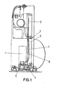
- the air conditioner includes a frame with a housing inside Compression means 1 of a refrigerant, an evaporator 2 and a condenser 3 are provided.
- a container 4 attached under the condenser 3 provided in which the water collected under this is collected, furthermore a pipe 6 connected to a pump 5 for transport the water from the container 4 to the collector 7, which is between the evaporator 2 and the capacitor 3 is attached, is provided.
- the collector 7 extends at least approximately on the length of the evaporator 2 and the condenser Third
- the water that is collected by the collector 7 must be emptied or flow over the condenser 3 to cool the latter cause.
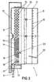
- the collector shows the Arrangement, which is shown in detail in Figures 3, 4 and 5.
- a first distribution section 8 is provided, which is above a second Distribution section 9 is attached and as a cover for this second section 9 serves (see Figure 5).
- These distribution sections are fastened rotatably by means of a Connecting element, for example a plastic hinge 10.
- this section 8 is in the form of an angle profile designed at the apex 11 or near this drain openings 12 are provided.
- the drain openings 12 have the same Diameter and are at least approximately in a row along the Apex 11 of the angle profile arranged.
- the second distribution section 9 comprises two areas 13, 14 with their corresponding drain openings 15, 16. According to the invention is the Diameter of the drain openings 12 of the first distribution section 8 larger in relation to the openings 15, 16 which are in the second distribution section 9 are provided.
- drain openings 12 of the first extend Distribution section 8 approximately evenly over the arrangement of the Drain openings 15, 16 in the second distribution section 9.
- This second distribution section 9 has at least two areas 13, 14 a different opening extension of the drain openings.
- the area 14 has a larger surface area of the drain openings than that Area 13, and this area 14 is closer to the connecting element 17 for the connection of the tube 6, which is part of the system for transporting the Water that is collected in the container 4 is to the collector 7.
- the area 14 which has a larger surface area of Has drainage openings, in the area 18 near the connecting element 17th a lower density of the drainage openings in relation to the rest of the surface of section 14.
- the water collected in the container 4 becomes a channel by means of the pump 5 the collector 7 transported.
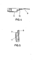
- section 18 with the reduced surface of the drain openings a baffle 19 of Condensed water flowing out of the connecting element 17, provided, this wall 19 partially in the area 14 with the largest expansion sum of the drain openings extends.
- the baffle device can only consist of the wall 19 in area 14, it can, however, also from said wall 19 and from another wall 20 exist, one behind the other in direction 21 of the Condensed water flow of the container 4 is located, creating a labyrinthine Phase shift is generated.
- the baffle 17 is at an acute angle in relation to the direction 21 of the Condensed water flow from the connecting element 17 to the second Distribution section 9 flows attached.
- Behind the baffle 17 is an opening 22 with a larger cross section than that Cross section of the openings 16 provided to ensure that in Area that is behind the wall, adequate drainage of the Condensed water takes place.
Landscapes
- Engineering & Computer Science (AREA)
- Chemical & Material Sciences (AREA)
- Combustion & Propulsion (AREA)
- Mechanical Engineering (AREA)
- General Engineering & Computer Science (AREA)
- Devices For Blowing Cold Air, Devices For Blowing Warm Air, And Means For Preventing Water Condensation In Air Conditioning Units (AREA)
- Vaporization, Distillation, Condensation, Sublimation, And Cold Traps (AREA)
- Air-Conditioning For Vehicles (AREA)
Claims (17)
- Dispositif de conditionnement d'air transportable comprenant un boítier dans lequel sont prévus un condensateur (3) et un évaporateur (2) prévu au dessus de celui-ci et sous lequel est prévu un collecteur (7) qui s'étend au moins à peu près sur la largeur de l'évaporateur (2) et du condensateur (3) et qui comprend un segment de répartition (8) pourvu d'ouvertures d'écoulement (12) pour l'eau de condensation gouttant depuis l'évaporateur (2) ainsi qu'un second segment de répartition (9) pourvu d'ouvertures d'écoulement (15, 16) qui est couvert par un couvercle et est rempli, à l'aide d'un dispositif de transport, avec l'eau de condensation qui s'est accumulée sous le condensateur (3), caractérisé en ce que le second segment de répartition (9) comporte au moins deux zones (13, 14) dans lesquelles la somme des dimensions d'ouverture des ouvertures d'écoulement (15, 16) est différente.
- Dispositif de conditionnement d'air transportable selon la revendication 1, caractérisé en ce qu'un raccord (17) servant à la connexion avec le dispositif de transport de l'eau accumulée sous le condensateur (3) est associé à la zone (14) dans laquelle la somme des dimensions d'ouverture des ouvertures d'écoulement est la plus grande.
- Dispositif de conditionnement d'air transportable selon la revendication 1 ou 2, caractérisé en ce que les différentes sommes des dimensions des ouvertures d'écoulement dans les deux zones (13, 14) résultent d'une densité de répartition correspondante des ouvertures d'écoulement qui sont pourvues d'une zone de section transversale d'ouverture uniforme.
- Dispositif de conditionnement d'air transportable selon l'une des revendications 1 à 3, caractérisé en ce que la zone (14) dans laquelle la somme des dimensions d'ouverture d'écoulement est la plus grande comporte, dans la zone (18) proche du raccord, un segment de surface dans lequel la dimension d'ouverture d'écoulement est réduite par rapport au reste de la surface de la zone (18).
- Dispositif de conditionnement d'air transportable selon l'une des revendications 1 à 4, caractérisé en ce qu'on prévoit, à la suite du segment de surface (18) dans lequel la dimension d'ouverture d'écoulement est réduite, un dispositif de paroi de rebondissement (19) pour l'eau de condensation sortant du raccord (17), qui s'étend, au moins partiellement, dans la zone des ouvertures d'écoulement de la zone (14) dans laquelle la somme des dimensions d'ouverture d'écoulement est la plus grande.
- Dispositif de conditionnement d'air transportable selon la revendication 5, caractérisé en ce que le dispositif de paroi de rebondissement (19) est formé d'au moins deux segments de paroi de rebondissement (19, 20), l'un se trouvant derrière l'autre dans la direction (21) d'écoulement de l'eau de condensation, grâce à quoi on obtient un décalage de phase à la manière d'un labyrinthe.
- Dispositif de conditionnement d'air transportable selon la revendication 6, caractérisé en ce qu'un des segments de paroi de rebondissement (20) est situé dans le premier segment de répartition (8) qui sert de couvercle, tandis que l'autre segment de paroi de rebondissement (19) est prévu dans le second élément de répartition (9).
- Dispositif de conditionnement d'air transportable selon la revendication 6 ou 7, caractérisé en ce que le dispositif de paroi de rebondissement (19) est disposé suivant un angle aigu par rapport à la direction d'écoulement (21) de l'eau de condensation qui s'écoule du raccord (17) vers le second segment de répartition (9).
- Dispositif de conditionnement d'air transportable selon la revendication 7, caractérisé en ce qu'une ouverture (22) dont la dimension d'ouverture est agrandie par rapport à la dimension d'ouverture d'une ouverture d'écoulement est située derrière le segment de paroi de rebondissement (19) situé dans le second segment de répartition (9) dans la direction d'écoulement (21) de l'eau de condensation qui s'écoule à travers le raccord (17).
- Dispositif de conditionnement d'air transportable selon la revendication 1, caractérisé en ce que le premier segment de répartition (8) est situé au dessus dusecond segment de répartition (9) auquel il sert de couvercle.
- Dispositif de conditionnement d'air transportable selon la revendication 1 ou 10, caractérisé en ce que le premier segment de répartition (8) est fixé de manière rotative sur le second segment de répartition (9).
- Dispositif de conditionnement d'air transportable selon la revendication 11, caractérisé en ce que la fixation rotative entre le premier (8) et le second segment de répartition (9) est formée d'au moins un élément de liaison sous la forme d'une charnière en matière plastique (10).
- Dispositif de conditionnement d'air transportable selon l'une des revendications 10 à 12, caractérisé en ce que le premier segment de répartition (8) est exécuté en tant que cornière qui est pourvue des ouvertures d'écoulement (12) au moins approximativement dans la zone proche de son sommet (11).
- Dispositif de conditionnement d'air transportable selon la revendication 13, caractérisé en ce que les ouvertures d'écoulement (12) du premier segment de répartition (8) présentent entre elles une zone de section transversale d'ouverture au moins essentiellement uniforme et sont disposées au moins approximativement en une rangée le long du sommet (11) de la cornière.
- Dispositif de conditionnement d'air transportable selon la revendication 13 ou 14, caractérisé en ce que la dimension d'ouverture des ouvertures d'écoulement individuelles (12) dans le premier segment de répartition (8) est agrandie par rapport à la dimension d'ouverture des ouvertures d'écoulement individuelles (15, 16) dans le second segment de répartition (9).
- Dispositif de conditionnement d'air transportable selon l'une des revendications 13 à 15, caractérisé en ce que les ouvertures d'écoulement (12) dans le premier segment de répartition (8) s'étendent de manière à peu près uniforme au dessus de l'arrangement des ouvertures d'écoulement (15, 16) dans le second segment de répartition (9).
- Dispositif de conditionnement d'air transportable selon la revendication 1 ou 2, caractérisé en ce que le dispositif de transport est exécuté en tant que pompe (5) commandée par moteur.
Applications Claiming Priority (2)
| Application Number | Priority Date | Filing Date | Title |
|---|---|---|---|
| ES9801749 | 1998-08-13 | ||
| ES009801749A ES2161584B1 (es) | 1998-08-13 | 1998-08-13 | Acondicionador de aire movil. |
Publications (3)
| Publication Number | Publication Date |
|---|---|
| EP0981030A2 EP0981030A2 (fr) | 2000-02-23 |
| EP0981030A3 EP0981030A3 (fr) | 2001-10-31 |
| EP0981030B1 true EP0981030B1 (fr) | 2004-05-06 |
Family
ID=8304903
Family Applications (1)
| Application Number | Title | Priority Date | Filing Date |
|---|---|---|---|
| EP99114949A Expired - Lifetime EP0981030B1 (fr) | 1998-08-13 | 1999-07-30 | Dispositif de conditionnement d'air transportable |
Country Status (4)
| Country | Link |
|---|---|
| EP (1) | EP0981030B1 (fr) |
| AT (1) | ATE266180T1 (fr) |
| DE (1) | DE59909377D1 (fr) |
| ES (2) | ES2161584B1 (fr) |
Cited By (1)
| Publication number | Priority date | Publication date | Assignee | Title |
|---|---|---|---|---|
| EP1672294A2 (fr) | 2004-12-14 | 2006-06-21 | BSH Bosch und Siemens Hausgeräte GmbH | Système de conditionnement d'air |
Families Citing this family (5)
| Publication number | Priority date | Publication date | Assignee | Title |
|---|---|---|---|---|
| ES2234442B1 (es) * | 2004-12-16 | 2006-11-01 | Bsh Electrodomesticos España, S.A. | Aparato de aire acondicionado. |
| US7735332B2 (en) | 2006-07-03 | 2010-06-15 | Lg Electronics Inc. | Air conditioner |
| US20080000252A1 (en) * | 2006-07-03 | 2008-01-03 | Jong Ho Lee | Air conditioner |
| CN101153726B (zh) * | 2006-09-29 | 2010-05-12 | 关存良 | 一种整体式可移动多功能节能空调机 |
| CN112197352A (zh) * | 2019-06-21 | 2021-01-08 | 苏州昆拓热控系统股份有限公司 | 便携式制冷循环设备、制冷组件及其壳体和制造方法 |
Family Cites Families (7)
| Publication number | Priority date | Publication date | Assignee | Title |
|---|---|---|---|---|
| US3766751A (en) * | 1972-05-02 | 1973-10-23 | Carrier Corp | Air conditioning unit with condensate disposal |
| US3898865A (en) * | 1974-04-30 | 1975-08-12 | Westinghouse Electric Corp | Condensate disposal apparatus for an air conditioner |
| US4067206A (en) * | 1976-09-15 | 1978-01-10 | Admiral Corporation | Condensate evaporation system for air conditioners |
| JPS60245940A (ja) * | 1984-05-18 | 1985-12-05 | Nippon Denso Co Ltd | 冷房装置 |
| EP0450273B1 (fr) * | 1990-03-30 | 1994-12-07 | Kabushiki Kaisha Toshiba | Appareil de conditionnement |
| US5461879A (en) * | 1994-04-19 | 1995-10-31 | Carrier Corporation | Air conditioner condensate slinger |
| JPH08285322A (ja) * | 1995-04-14 | 1996-11-01 | Matsushita Seiko Co Ltd | 局所冷房機のドレン水蒸発装置 |
-
1998
- 1998-08-13 ES ES009801749A patent/ES2161584B1/es not_active Expired - Fee Related
-
1999
- 1999-07-30 EP EP99114949A patent/EP0981030B1/fr not_active Expired - Lifetime
- 1999-07-30 ES ES99114949T patent/ES2222012T3/es not_active Expired - Lifetime
- 1999-07-30 DE DE59909377T patent/DE59909377D1/de not_active Expired - Lifetime
- 1999-07-30 AT AT99114949T patent/ATE266180T1/de not_active IP Right Cessation
Cited By (2)
| Publication number | Priority date | Publication date | Assignee | Title |
|---|---|---|---|---|
| EP1672294A2 (fr) | 2004-12-14 | 2006-06-21 | BSH Bosch und Siemens Hausgeräte GmbH | Système de conditionnement d'air |
| DE202005021622U1 (de) | 2004-12-14 | 2008-12-24 | BSH Bosch und Siemens Hausgeräte GmbH | Klimagerät |
Also Published As
| Publication number | Publication date |
|---|---|
| ATE266180T1 (de) | 2004-05-15 |
| ES2161584A1 (es) | 2001-12-01 |
| ES2161584B1 (es) | 2002-06-16 |
| EP0981030A2 (fr) | 2000-02-23 |
| ES2222012T3 (es) | 2005-01-16 |
| EP0981030A3 (fr) | 2001-10-31 |
| DE59909377D1 (de) | 2004-06-09 |
Similar Documents
| Publication | Publication Date | Title |
|---|---|---|
| DE60102309T2 (de) | Wärmeaustauschmodul, insbesondere für Kraftfahrzeuge | |
| DE3930076C1 (fr) | ||
| DE19505213C1 (de) | Luftzuführeinrichtung | |
| DE7837590U1 (de) | Luftansaugvorrichtung fuer eine brennkraftmaschine | |
| DE2638481C3 (de) | Verdampfer für eine Klimaanlage | |
| DE102006018681A1 (de) | Wärmetauscher für ein Fahrzeug | |
| DE19609687C2 (de) | Wandkühlgerät für einen Schaltsschrank mit einem Lüfter und einem Lamellen-Wärmetauscher | |
| DE2524022A1 (de) | Kuehlvorrichtung | |
| DE19734146C2 (de) | Luftzuführeinrichtung | |
| DE202017102138U1 (de) | Wärmetauschereinrichtung | |
| DE2509630C3 (de) | Filtereinrichtung für einen Verdunstungswärmetauscher | |
| EP0981030B1 (fr) | Dispositif de conditionnement d'air transportable | |
| EP1522804B1 (fr) | Dispositif de fixation d'agent déshydratant dans un condenseur et condenseur | |
| WO2008116572A1 (fr) | Condensateur | |
| DE3223812A1 (de) | Klimaanlage fuer kraftfahrzeuge | |
| DE8019939U1 (de) | Luftverteileinrichtung insbesondere fuer uebersaettigte luft | |
| DE3623185C2 (fr) | ||
| DE102004059680B4 (de) | Bauanordnung für Einrichtungen zum Austausch von Wärme | |
| DE2559992C3 (de) | Tropfenabscheider bei einer Vorrichtung zum Kühlen durch Verdunsten eingespritzter Flüssigkeit | |
| DE19513201C1 (de) | Tropfenabscheider für eine dezentrale Heizungs-, Lüftungs- und/oder Kühlvorrichtung | |
| EP0162993A1 (fr) | Tour de réfrigération humide ou combinée par voies humides et sèches | |
| DE3510277A1 (de) | Bruedenkondensor | |
| DE10250287C1 (de) | Wärmetauscher, insbesondere für eine Heiz- und/oder Klimaeinrichtung eines Kraftfahzeuges | |
| DE4017229C2 (fr) | ||
| DE4322951C1 (de) | Kraftfahrzeug mit unterhalb der Frontscheibe angeordneter Lufteintrittsöffnung |
Legal Events
| Date | Code | Title | Description |
|---|---|---|---|
| PUAI | Public reference made under article 153(3) epc to a published international application that has entered the european phase |
Free format text: ORIGINAL CODE: 0009012 |
|
| AK | Designated contracting states |
Kind code of ref document: A2 Designated state(s): AT BE CH CY DE DK ES FI FR GB GR IE IT LI LU MC NL PT SE |
|
| AX | Request for extension of the european patent |
Free format text: AL;LT;LV;MK;RO;SI |
|
| RIN1 | Information on inventor provided before grant (corrected) |
Inventor name: SCHMUELLING, RALF Inventor name: GONZALES, JUAN Inventor name: BARCOS, JESUS Inventor name: ARRAIZA, JAIME |
|
| PUAL | Search report despatched |
Free format text: ORIGINAL CODE: 0009013 |
|
| AK | Designated contracting states |
Kind code of ref document: A3 Designated state(s): AT BE CH CY DE DK ES FI FR GB GR IE IT LI LU MC NL PT SE |
|
| AX | Request for extension of the european patent |
Free format text: AL;LT;LV;MK;RO;SI |
|
| RIC1 | Information provided on ipc code assigned before grant |
Free format text: 7F 24F 1/04 A, 7F 24F 13/22 B, 7F 24F 1/02 B |
|
| 17P | Request for examination filed |
Effective date: 20020502 |
|
| AKX | Designation fees paid |
Free format text: AT BE CH CY DE DK ES FI FR GB GR IE IT LI LU MC NL PT SE |
|
| GRAP | Despatch of communication of intention to grant a patent |
Free format text: ORIGINAL CODE: EPIDOSNIGR1 |
|
| GRAS | Grant fee paid |
Free format text: ORIGINAL CODE: EPIDOSNIGR3 |
|
| GRAA | (expected) grant |
Free format text: ORIGINAL CODE: 0009210 |
|
| STAA | Information on the status of an ep patent application or granted ep patent |
Free format text: STATUS: THE PATENT HAS BEEN GRANTED |
|
| AK | Designated contracting states |
Kind code of ref document: B1 Designated state(s): AT BE CH CY DE DK ES FI FR GB GR IE IT LI LU MC NL PT SE |
|
| PG25 | Lapsed in a contracting state [announced via postgrant information from national office to epo] |
Ref country code: NL Free format text: LAPSE BECAUSE OF FAILURE TO SUBMIT A TRANSLATION OF THE DESCRIPTION OR TO PAY THE FEE WITHIN THE PRESCRIBED TIME-LIMIT Effective date: 20040506 Ref country code: IE Free format text: LAPSE BECAUSE OF FAILURE TO SUBMIT A TRANSLATION OF THE DESCRIPTION OR TO PAY THE FEE WITHIN THE PRESCRIBED TIME-LIMIT Effective date: 20040506 Ref country code: FI Free format text: LAPSE BECAUSE OF FAILURE TO SUBMIT A TRANSLATION OF THE DESCRIPTION OR TO PAY THE FEE WITHIN THE PRESCRIBED TIME-LIMIT Effective date: 20040506 Ref country code: CY Free format text: LAPSE BECAUSE OF FAILURE TO SUBMIT A TRANSLATION OF THE DESCRIPTION OR TO PAY THE FEE WITHIN THE PRESCRIBED TIME-LIMIT Effective date: 20040506 |
|
| REG | Reference to a national code |
Ref country code: GB Ref legal event code: FG4D Free format text: NOT ENGLISH |
|
| REG | Reference to a national code |
Ref country code: CH Ref legal event code: EP |
|
| REF | Corresponds to: |
Ref document number: 59909377 Country of ref document: DE Date of ref document: 20040609 Kind code of ref document: P |
|
| REG | Reference to a national code |
Ref country code: IE Ref legal event code: FG4D Free format text: GERMAN |
|
| GBT | Gb: translation of ep patent filed (gb section 77(6)(a)/1977) |
Effective date: 20040621 |
|
| PG25 | Lapsed in a contracting state [announced via postgrant information from national office to epo] |
Ref country code: LU Free format text: LAPSE BECAUSE OF NON-PAYMENT OF DUE FEES Effective date: 20040730 Ref country code: AT Free format text: LAPSE BECAUSE OF NON-PAYMENT OF DUE FEES Effective date: 20040730 |
|
| PG25 | Lapsed in a contracting state [announced via postgrant information from national office to epo] |
Ref country code: MC Free format text: LAPSE BECAUSE OF NON-PAYMENT OF DUE FEES Effective date: 20040731 Ref country code: LI Free format text: LAPSE BECAUSE OF NON-PAYMENT OF DUE FEES Effective date: 20040731 Ref country code: CH Free format text: LAPSE BECAUSE OF NON-PAYMENT OF DUE FEES Effective date: 20040731 Ref country code: BE Free format text: LAPSE BECAUSE OF NON-PAYMENT OF DUE FEES Effective date: 20040731 |
|
| PG25 | Lapsed in a contracting state [announced via postgrant information from national office to epo] |
Ref country code: SE Free format text: LAPSE BECAUSE OF FAILURE TO SUBMIT A TRANSLATION OF THE DESCRIPTION OR TO PAY THE FEE WITHIN THE PRESCRIBED TIME-LIMIT Effective date: 20040806 Ref country code: GR Free format text: LAPSE BECAUSE OF FAILURE TO SUBMIT A TRANSLATION OF THE DESCRIPTION OR TO PAY THE FEE WITHIN THE PRESCRIBED TIME-LIMIT Effective date: 20040806 Ref country code: DK Free format text: LAPSE BECAUSE OF FAILURE TO SUBMIT A TRANSLATION OF THE DESCRIPTION OR TO PAY THE FEE WITHIN THE PRESCRIBED TIME-LIMIT Effective date: 20040806 |
|
| RAP2 | Party data changed (patent owner data changed or rights of a patent transferred) |
Owner name: BSH BOSCH UND SIEMENS HAUSGERAETE GMBH |
|
| NLT2 | Nl: modifications (of names), taken from the european patent patent bulletin |
Owner name: BSH BOSCH UND SIEMENS HAUSGERAETE GMBH |
|
| NLV1 | Nl: lapsed or annulled due to failure to fulfill the requirements of art. 29p and 29m of the patents act | ||
| REG | Reference to a national code |
Ref country code: IE Ref legal event code: FD4D |
|
| REG | Reference to a national code |
Ref country code: ES Ref legal event code: FG2A Ref document number: 2222012 Country of ref document: ES Kind code of ref document: T3 |
|
| BERE | Be: lapsed |
Owner name: BSH FABRICACION, S.A. Effective date: 20040731 |
|
| ET | Fr: translation filed | ||
| PLBE | No opposition filed within time limit |
Free format text: ORIGINAL CODE: 0009261 |
|
| REG | Reference to a national code |
Ref country code: CH Ref legal event code: PL |
|
| 26N | No opposition filed |
Effective date: 20050208 |
|
| BERE | Be: lapsed |
Owner name: S.A. *BSH FABRICACION Effective date: 20040731 |
|
| PG25 | Lapsed in a contracting state [announced via postgrant information from national office to epo] |
Ref country code: PT Free format text: LAPSE BECAUSE OF NON-PAYMENT OF DUE FEES Effective date: 20041006 |
|
| REG | Reference to a national code |
Ref country code: GB Ref legal event code: 732E |
|
| PGFP | Annual fee paid to national office [announced via postgrant information from national office to epo] |
Ref country code: GB Payment date: 20120723 Year of fee payment: 14 |
|
| PGFP | Annual fee paid to national office [announced via postgrant information from national office to epo] |
Ref country code: FR Payment date: 20120803 Year of fee payment: 14 Ref country code: IT Payment date: 20120725 Year of fee payment: 14 Ref country code: ES Payment date: 20120723 Year of fee payment: 14 Ref country code: DE Payment date: 20120731 Year of fee payment: 14 |
|
| GBPC | Gb: european patent ceased through non-payment of renewal fee |
Effective date: 20130730 |
|
| REG | Reference to a national code |
Ref country code: DE Ref legal event code: R119 Ref document number: 59909377 Country of ref document: DE Effective date: 20140201 |
|
| REG | Reference to a national code |
Ref country code: FR Ref legal event code: ST Effective date: 20140331 |
|
| PG25 | Lapsed in a contracting state [announced via postgrant information from national office to epo] |
Ref country code: DE Free format text: LAPSE BECAUSE OF NON-PAYMENT OF DUE FEES Effective date: 20140201 Ref country code: GB Free format text: LAPSE BECAUSE OF NON-PAYMENT OF DUE FEES Effective date: 20130730 |
|
| PG25 | Lapsed in a contracting state [announced via postgrant information from national office to epo] |
Ref country code: FR Free format text: LAPSE BECAUSE OF NON-PAYMENT OF DUE FEES Effective date: 20130731 Ref country code: IT Free format text: LAPSE BECAUSE OF NON-PAYMENT OF DUE FEES Effective date: 20130730 |
|
| REG | Reference to a national code |
Ref country code: ES Ref legal event code: FD2A Effective date: 20140905 |
|
| PG25 | Lapsed in a contracting state [announced via postgrant information from national office to epo] |
Ref country code: ES Free format text: LAPSE BECAUSE OF NON-PAYMENT OF DUE FEES Effective date: 20130731 |