EP0980761A1 - Transport-Mechanismus eines Druckkopfes - Google Patents
Transport-Mechanismus eines Druckkopfes Download PDFInfo
- Publication number
- EP0980761A1 EP0980761A1 EP99306488A EP99306488A EP0980761A1 EP 0980761 A1 EP0980761 A1 EP 0980761A1 EP 99306488 A EP99306488 A EP 99306488A EP 99306488 A EP99306488 A EP 99306488A EP 0980761 A1 EP0980761 A1 EP 0980761A1
- Authority
- EP
- European Patent Office
- Prior art keywords
- carriage
- sub
- print head
- traverse
- guide
- Prior art date
- Legal status (The legal status is an assumption and is not a legal conclusion. Google has not performed a legal analysis and makes no representation as to the accuracy of the status listed.)
- Granted
Links
Images


Classifications
-
- B—PERFORMING OPERATIONS; TRANSPORTING
- B41—PRINTING; LINING MACHINES; TYPEWRITERS; STAMPS
- B41J—TYPEWRITERS; SELECTIVE PRINTING MECHANISMS, i.e. MECHANISMS PRINTING OTHERWISE THAN FROM A FORME; CORRECTION OF TYPOGRAPHICAL ERRORS
- B41J25/00—Actions or mechanisms not otherwise provided for
- B41J25/001—Mechanisms for bodily moving print heads or carriages parallel to the paper surface
- B41J25/005—Mechanisms for bodily moving print heads or carriages parallel to the paper surface for serial printing movements superimposed to character- or line-spacing movements
-
- B—PERFORMING OPERATIONS; TRANSPORTING
- B41—PRINTING; LINING MACHINES; TYPEWRITERS; STAMPS
- B41J—TYPEWRITERS; SELECTIVE PRINTING MECHANISMS, i.e. MECHANISMS PRINTING OTHERWISE THAN FROM A FORME; CORRECTION OF TYPOGRAPHICAL ERRORS
- B41J19/00—Character- or line-spacing mechanisms
- B41J19/14—Character- or line-spacing mechanisms with means for effecting line or character spacing in either direction
-
- B—PERFORMING OPERATIONS; TRANSPORTING
- B41—PRINTING; LINING MACHINES; TYPEWRITERS; STAMPS
- B41J—TYPEWRITERS; SELECTIVE PRINTING MECHANISMS, i.e. MECHANISMS PRINTING OTHERWISE THAN FROM A FORME; CORRECTION OF TYPOGRAPHICAL ERRORS
- B41J25/00—Actions or mechanisms not otherwise provided for
- B41J25/001—Mechanisms for bodily moving print heads or carriages parallel to the paper surface
-
- G—PHYSICS
- G06—COMPUTING; CALCULATING OR COUNTING
- G06K—GRAPHICAL DATA READING; PRESENTATION OF DATA; RECORD CARRIERS; HANDLING RECORD CARRIERS
- G06K15/00—Arrangements for producing a permanent visual presentation of the output data, e.g. computer output printers
- G06K15/02—Arrangements for producing a permanent visual presentation of the output data, e.g. computer output printers using printers
- G06K15/10—Arrangements for producing a permanent visual presentation of the output data, e.g. computer output printers using printers by matrix printers
- G06K15/102—Arrangements for producing a permanent visual presentation of the output data, e.g. computer output printers using printers by matrix printers using ink jet print heads
- G06K15/105—Multipass or interlaced printing
Definitions
- This invention relates to transport mechanisms for moving a print head relative to a print receiving medium.
- Print head transport mechanisms are known in which a digital print head is traversed alternately in opposite directions across the width of a print receiving medium. Such mechanisms are used in computer output printers in which a plurality of lines of printing are effected on a sheet of paper. After a traverse of the print head across the print receiving medium in which a line of printing is effected, the print receiving medium is fed, in a direction perpendicular to the traverse of the print head, so as to move the line of printing away from alignment with the line of traverse of the print head and to bring an unprinted portion of the print receiving medium into alignment with the traverse of the print head.
- the print heads may be impact wire dot print heads, ink jet print heads, thermal print heads or other types of print head in which a plurality of print elements are selectively operated to effect printing.
- the wires of the impact wire dot print heads are aligned in a row and likewise the ink jet print heads include a plurality of ink jet nozzles aligned in a row and thermal print heads include a plurality of thermal printing elements aligned in a row. Selective actuation of the wires, nozzles or thermal printing elements enables printing of dots of ink at selected positions aligned with the row of print elements.
- the traverse of the print head is perpendicular to the row of print elements and hence, as is well known, selective actuation of the print elements during traverse of the print head is effective to print desired characters and patterns on the print receiving medium. It will be appreciated that the maximum height of character that can be printed in a traverse of the print head is determined by the length of the row of print elements.
- ink jet print heads for printing postal indicia on mail items.
- the required height of the postal indicia is greater than the length of the row of ink jet nozzles in commonly commercially available ink jet print heads.
- a print head transport mechanism including a carriage mounted on a chassis for traversal relative to said chassis in a first direction and in a second direction opposite to said first direction over and beyond a print receiving area; means for driving the carriage alternately in said first and second directions is charactersied by a sub-carriage for mounting a print head, said sub-carriage being mounted on said carriage for traversal relative to the carriage in a third direction substantially parallel to said print receiving area and transverse to said first and second directions; a guide mounted on the chassis; means on the sub-carriage engaging with said guide; said guide having a formation such as to maintain the sub-carriage in a first index position when the carriage is traversed in the first direction, to maintain the sub-carriage in a second index position displaced from the first index position when the carriage is traversed in the second direction, to effect traverse of the sub-carriage from said first index position to said second index position each time the carriage is traversed in said first direction beyond the print receiving area and to effect traverse of the
- a carriage 10 is mounted on a guide rod 11 supported on a chassis 12.
- the carriage 10 is slidingly mounted by means of a bearing 13 on the guide rod 11 to permit the carriage to traverse lengthwise along the guide rod in the directions indicated by arrows 14, 15.
- the carriage may be traversed along the guide rod by any suitable drive means.
- a belt 40 may be provided that has a portion 41 thereof extending parallel to the guide rod.
- the belt passes around a drive pulley 42 and a resiliently mounted tension pulley 43 maintains the belt in tension.
- the drive pulley is driven from a shaft of a drive motor.
- the carriage 10 is secured to the portion 41 of the belt that extends parallel to the guide rod.
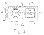
- An ink jet print head 16 is releasably mounted on the carriage.
- the print head 16 includes a line of ink jet nozzles indicated at 17 ( Figure 2).
- the ink jet nozzles are directed to eject droplets of ink through an aperture 18 in the chassis 12 toward a print receiving area 44 of a mail item 45 located below the chassis.
- the line of ink jet nozzles extends transversely to the direction of traverse of the carriage 10 and hence during traverse of the carriage the ink jet nozzles are traversed over a strip of the mail item.
- the required height dimension 46 of a postal indicium 47 to be printed on a mail piece 45 by the print head 16 is greater than the length of the line of ink jet nozzles 17. Accordingly the postal indicium is printed during two traverses of the print head.
- a first traverse of the print head for example in the direction of arrow 14, the line of ink jet nozzles are aligned with and traverse a first strip 48 of the print receiving area 44 in which the indicium is to be printed and then prior to a second traverse of the print head in the opposite direction, the print head is displaced in a direction, orthogonal to the traversing of the carriage 10 in the directions of arrows 14, 15, indicated by arrow 19 to align the ink jet nozzles with a second immediately adjacent strip 49 of the print receiving area 44 in which the indicium 47 is to be printed.
- a first band of the indicium is printed and in the second traverse of the print head a second band, immediately adjacent the first band, of the indicium is printed.
- the postal indicium illustrated in Figure 3 is a postal indicia currently in use in the United Kingdom and is shown merely by way of example and that the printing apparatus may be used to print other desired forms of postal indicia.
- the carriage 10 carries a sub-carriage 20 which is mounted on the carriage to permit indexing traversal of the sub-carriage relative to the carriage 10 from a home position to an index position in the direction of arrow 19 and return of the sub-carriage to the home position in a direction opposite to that of arrow 19.
- the sub-carriage 20 may be mounted on the carriage 10 for traversal relative to the carriage by means of studs 30, 31 on the sub-carriage 20 engaging in slots, of which one slot 32 receiving the stud 31 is shown.
- Indexing traversal of the sub-carriage is effected by means of a pin 21 on the sub-carriage 20 engaging with a track 22 of a guide plate 23 secured to the chassis 12.
- the track 22 comprises a groove having two branches 24, 25 extending parallel to one another and offset relative to one another in a direction parallel to the arrow 19.
- the two branches 24, 25 join together thereby forming a continuous loop track and the branch 24 has an extension 33 beyond the junction 27.
- the track branch 24 is of arcuate form to join with the end of branch 25 and at the junction 27 the track branch 25 is of arcuate form to join into branch 24.
- the pin 21 When the carriage is traversed in the direction of arrow 14, the pin 21 is engaged in the track branch 24 and the sub-carriage is maintained in a home position. As the carriage nears the end of branch 24, the pin 21 enters the arcuate portion of the branch 24 and as a result the pin 21 is moved transversely to the end of track branch 25. Transverse movement of the pin 21 into track branch 25 causes a corresponding indexing displacement of the sub-carriage from the home position to an index position. The drive to the carriage is then reversed and the pin 21 travels along the track branch 25 to maintain the sub-carriage in the second index position.
- the pin 21 enters the arcuate end portion of the branch 25 and as a result the pin is moved transversely and is returned to the track branch 24.
- This transverse movement of the pin into track branch 24 causes a corresponding indexing displacement of the sub-carriage from the index position back to the home position.
- the wall of the groove forms a cam surface 28.
- the cam surface 28 acts to guide the pin 21 into that one of the track branches along which the pin is required to travel.
- the extension 33 of track branch 24 beyond the junction 27 of the two track branches permits the carriage to be traversed out of and beyond the printing region into a service station for the print head.
- the relative transverse offset of the track branches 24, 25 may be equal to an offset required to provide the intended indexing traverse of the sub-carriage.
- the location of the print head in a transverse direction is directly dependent upon the engagement between the pin 21 and the walls of the groove track, tolerances in manufacture of the track 22 and wear of the walls of the groove track of the pin 21 would result in imprecise positioning of the print head. Accordingly it is preferred to mount the pin 22 on the sub-carriage 20 with a freedom of movement in the direction of indexing traversal of the sub-carriage and the pin 21 is spring biased to a central position.
- the transverse offset of the track branches is slightly greater than would be required to provide the intended index traversal of the sub-carriage and hence the engagement of the pin 21 in the grooved track causes the pin to be displaced against the spring biassing to an extent slightly greater than required to cause the intended indexing displacement of the sub-carriage.
- the indexing displacement of the sub-carriage is limited by abutments to precisely locate the sub-carriage at either the home or index positions. Hence the pin is displaced against spring force relative to the sub-carriage and thereby maintains the sub-carriage under spring force against one or other of the limit abutments.
- the sub-carriage has a home position in which abutment of a face 36 of the sub-carriage 20 and a face 37 of the carriage 10 precisely locates the sub-carriage.
- Indexing displacement of the sub-carriage from the home position in the direction of arrow 19 may be limited by abutment of a face 34 of the sub-carriage 20 against a face 35 of the carriage 10 whereby the sub-carriage is precisely located in the index position.
- the location of the sub-carriage in the home and index positions may be determined by engagement of a stud in a slot of precise length, for example by engagement of the stud 31 in the slot 32, the ends of the slot being precisely located so as to precisely determine the required locations of the sub-carriage in the home and index positions.
- position determining means comprising the faces on the sub-carriage and carriage or by the stud and the slot
- other position determining means for example a detent mechanism may be provided to ensure displacement of the sub-carriage to precisely determined home and index positions.
- the carriage is traversed in a first direction in the direction of arrow 14 and the ink jet nozzles are operated selectively to print a first band of the postal indicium.
- the pin 21 is caused by the arcuate form of the track branch 24 to traverse across to the track branch 25 and thereby indexes the sub-carriage from the home position to the index position.
- the traverse of the carriage is then reversed and during traverse of the printing area the ink jet nozzles are again selectively operated to print a second band of the postal indicium immediately adjoining the first band.
- the pin 21 follows the end of track branch 25 into track branch 24 and thereby traverses the sub-carriage back to the home position thereof.
- the pin 21 spring biassed relative to the sub-carriage, the pin is urged into engagement with one side wall of the guide track and hence the track branches 24, 25 may be constituted by side walls of a guide island 50 of the guide plate 23. Accordingly the guide plate may have a construction illustrated in Figures 4 and 5 to which reference will now be made.
- the guide island 50 has side walls 51, 52 which extend parallel to one another and are spaced from one another by a distance slightly greater than required for displacing the sub-carriage from the home position to the index position and from the index position to the home position. Ends 53, 54 of the guide island side walls 51, 52 are shaped to permit the guide pin of the sub-carriage to move from engagement with that one of the walls 51, 52 with which the pin has been engaged during a traverse of the carriage in a first direction into a position where the pin can move into engagement with the other one of the side walls during a next succeeding traverse of the carriage in a reverse direction.
- Cam walls 55, 56 are provided at the ends of the guide plate.
- a detent or other means may be provided effective to maintain the sub-carriage in the home and index positions.
- the sub-carriage will tend to remain in either the home or the index position to which it has been displaced when the carriage is at either end of its traverse and the pin is not in engagement with a guide wall 51 or 52.
- the apparatus is subjected to sudden shock or if the direction of displacement is an angle to the horizontal the sub-carriage may tend to move away from the home or index position to which is has been moved by the guide plate.
- the pin is prevented by the flap 63 from moving back to the home position into engagement with guide wall 51 and is constrained to move into engagement with the guide wall 52.
- resilience of the flaps permits the pin to pass over the flaps.
- the pin may be a non-rotatable member which slides in engagement with the guide and cam walls or, preferably, is a rotatable roller.
- the print head transport mechanism has been described hereinbefore for traversing and indexing an ink jet print head relative to an area of a mail item to receive an imprint of a postal indicia. It is to be understood that the transport mechanism may also be used for similarly traversing and indexing other forms of print head where the impression required to be printed is of greater width than the span of the printing elements of the print head. For example the transport mechanism may be used for traversing and indexing wire dot impact, thermal, magnetic and other types of print head.
- the print head may be utilised for printing a composite pattern, for example a postal indicium in two traverses or may be used for printing other imprints which have a dimension greater than the span of the print head elements.
- the extent of traverse of the sub-carriage between the home and index positions may be approximately equal to the span of the printing elements of the print head whereby an impression having a width equal to twice the span of the printing elements may be printed.
- the printing head may be indexed to a lesser extent such that the strips of the printing area traversed by the printing elements overlap.
- those ones of the printing elements that traverse the region of the overlap are operated in such a manner that there is no overlap in the printing that is effected by the printing elements.
Landscapes
- Physics & Mathematics (AREA)
- Engineering & Computer Science (AREA)
- Mathematical Physics (AREA)
- General Engineering & Computer Science (AREA)
- General Physics & Mathematics (AREA)
- Theoretical Computer Science (AREA)
- Character Spaces And Line Spaces In Printers (AREA)
- Ink Jet (AREA)
Applications Claiming Priority (2)
| Application Number | Priority Date | Filing Date | Title |
|---|---|---|---|
| GB9818026 | 1998-08-18 | ||
| GBGB9818026.8A GB9818026D0 (en) | 1998-08-18 | 1998-08-18 | Print head transport mechanism |
Publications (2)
| Publication Number | Publication Date |
|---|---|
| EP0980761A1 true EP0980761A1 (de) | 2000-02-23 |
| EP0980761B1 EP0980761B1 (de) | 2005-10-26 |
Family
ID=10837472
Family Applications (1)
| Application Number | Title | Priority Date | Filing Date |
|---|---|---|---|
| EP99306488A Expired - Lifetime EP0980761B1 (de) | 1998-08-18 | 1999-08-17 | Transport-Mechanismus eines Druckkopfes |
Country Status (4)
| Country | Link |
|---|---|
| US (2) | US6447183B2 (de) |
| EP (1) | EP0980761B1 (de) |
| DE (1) | DE69927889T2 (de) |
| GB (1) | GB9818026D0 (de) |
Cited By (7)
| Publication number | Priority date | Publication date | Assignee | Title |
|---|---|---|---|---|
| EP1024016A2 (de) | 1999-01-29 | 2000-08-02 | Neopost Limited | Ausrichtung von Ausdrucken |
| EP1024014A2 (de) | 1999-01-29 | 2000-08-02 | Neopost Limited | Tintenstrahldruckermechanismus |
| EP1127701A1 (de) | 2000-02-24 | 2001-08-29 | Francotyp-Postalia Aktiengesellschaft & Co. | Druckvorrichtung mit Querführung zum Versetzen des Druckkopfs quer zur Druckrichtung |
| DE10009802A1 (de) * | 2000-02-24 | 2001-08-30 | Francotyp Postalia Gmbh | Druckvorrichtung und Druckverfahren mit beweglicher Druckkopfführung |
| DE10009800A1 (de) * | 2000-02-24 | 2001-08-30 | Francotyp Postalia Gmbh | Vorrichtung zum Führen eines Druckkopfs |
| CH696165A5 (de) * | 2002-05-10 | 2007-01-31 | Textilma Ag | Tintenstrahl Druckeranlage zum fortlaufenden Bedrucken eines textilen Flächengebildes. |
| EP2902975A1 (de) | 2014-01-31 | 2015-08-05 | Neopost Technologies | Büropostmaschine der Einstiegsklasse |
Families Citing this family (10)
| Publication number | Priority date | Publication date | Assignee | Title |
|---|---|---|---|---|
| GB9818026D0 (en) * | 1998-08-18 | 1998-10-14 | Neopost Ltd | Print head transport mechanism |
| US6524021B2 (en) * | 2000-12-05 | 2003-02-25 | Hewlett-Packard Company | Multiple orientation image forming device and carriage for use with same |
| US6789966B2 (en) * | 2001-02-28 | 2004-09-14 | Seiko Epson Corporation | Printer, carriage supporting structure and head assembly incorporated in the printer |
| KR100432241B1 (ko) * | 2001-06-25 | 2004-05-20 | 세이코 엡슨 가부시키가이샤 | 프린터 |
| US20030160840A1 (en) * | 2001-10-19 | 2003-08-28 | Haseeb Yusef | Carriage guide for inkjet printer |
| JP4254597B2 (ja) * | 2004-03-31 | 2009-04-15 | ブラザー工業株式会社 | 画像読取装置 |
| JP6508720B2 (ja) * | 2015-08-31 | 2019-05-08 | セイコーソリューションズ株式会社 | 印字ユニット及びプリンタ |
| JP6694337B2 (ja) * | 2016-06-22 | 2020-05-13 | セイコーソリューションズ株式会社 | 印字ユニット及びプリンタ |
| WO2021079946A1 (ja) * | 2019-10-25 | 2021-04-29 | キヤノンファインテックニスカ株式会社 | 記録装置 |
| JP6968963B2 (ja) * | 2019-10-25 | 2021-11-24 | キヤノンファインテックニスカ株式会社 | 記録装置 |
Citations (6)
| Publication number | Priority date | Publication date | Assignee | Title |
|---|---|---|---|---|
| US4365901A (en) * | 1980-05-22 | 1982-12-28 | U.S. Philips Corporation | Matrix printer with automatic printing head adjustment |
| DE3125426A1 (de) * | 1981-06-27 | 1983-01-20 | Olympia Werke Ag, 2940 Wilhelmshaven | Matrixdrucker mit einem laengs eines aufzeichnungstraegers in druckzeilenrichtung bewegbaren druckkopf |
| DE3213646A1 (de) * | 1982-04-14 | 1983-10-27 | Olympia Werke Ag, 2940 Wilhelmshaven | Verfahren und schaltungsanordnung zum schreiben gerasterter zeichen |
| US4774529A (en) * | 1987-02-26 | 1988-09-27 | Xerox Corporation | Repositionable marking head for increasing printing speed |
| EP0827839A1 (de) * | 1996-09-10 | 1998-03-11 | Hewlett-Packard Company | Mechanische Vorrichtung für Auslösungsverdoppelung |
| US5762428A (en) * | 1995-12-27 | 1998-06-09 | Pitney Bowes Inc. | Method and apparatus for securely printing a postal indicia image by dividing printing of the image in multiple passes |
Family Cites Families (10)
| Publication number | Priority date | Publication date | Assignee | Title |
|---|---|---|---|---|
| US2913090A (en) * | 1956-10-04 | 1959-11-17 | Commercial Controls Corp | Carriage mechanism for typewriters |
| FR2300678A1 (fr) * | 1975-02-13 | 1976-09-10 | Logabax | Dispositif d'impression pour imprimantes rapides |
| US4049109A (en) * | 1976-03-08 | 1977-09-20 | Xerox Corporation | Print member carriage assembly |
| EP0526209B1 (de) * | 1991-07-31 | 1997-11-05 | Canon Kabushiki Kaisha | Getriebe für Aufzeichnungsgeräte |
| DE69328703T2 (de) * | 1992-06-10 | 2000-12-28 | Canon Kk | Vorrichtung zur Bewegungsbegrenzung eines Aufzeichnungsmaterials in einem Aufzeichnungsgerät |
| JP3279475B2 (ja) | 1996-03-22 | 2002-04-30 | マックス株式会社 | 印字装置における印字ヘッドの前後移動機構 |
| US5889535A (en) * | 1996-09-23 | 1999-03-30 | Pitney Bowes Inc. | Postage meter including an inkjet printer which has an ink-jet maintenance head translating transverse to the movement of the inkjet print head |
| KR200153526Y1 (ko) | 1996-12-04 | 1999-08-02 | 윤종용 | 잉크젯 프린터의 용지두께에 따른 헤드갭 조정장치 |
| JP3739532B2 (ja) | 1997-06-06 | 2006-01-25 | セイコーエプソン株式会社 | インクジェット式記録装置 |
| GB9818026D0 (en) * | 1998-08-18 | 1998-10-14 | Neopost Ltd | Print head transport mechanism |
-
1998
- 1998-08-18 GB GBGB9818026.8A patent/GB9818026D0/en not_active Ceased
-
1999
- 1999-08-17 EP EP99306488A patent/EP0980761B1/de not_active Expired - Lifetime
- 1999-08-17 DE DE69927889T patent/DE69927889T2/de not_active Expired - Lifetime
- 1999-08-17 US US09/375,560 patent/US6447183B2/en not_active Expired - Lifetime
-
2002
- 2002-03-18 US US10/098,423 patent/US6695497B2/en not_active Expired - Lifetime
Patent Citations (6)
| Publication number | Priority date | Publication date | Assignee | Title |
|---|---|---|---|---|
| US4365901A (en) * | 1980-05-22 | 1982-12-28 | U.S. Philips Corporation | Matrix printer with automatic printing head adjustment |
| DE3125426A1 (de) * | 1981-06-27 | 1983-01-20 | Olympia Werke Ag, 2940 Wilhelmshaven | Matrixdrucker mit einem laengs eines aufzeichnungstraegers in druckzeilenrichtung bewegbaren druckkopf |
| DE3213646A1 (de) * | 1982-04-14 | 1983-10-27 | Olympia Werke Ag, 2940 Wilhelmshaven | Verfahren und schaltungsanordnung zum schreiben gerasterter zeichen |
| US4774529A (en) * | 1987-02-26 | 1988-09-27 | Xerox Corporation | Repositionable marking head for increasing printing speed |
| US5762428A (en) * | 1995-12-27 | 1998-06-09 | Pitney Bowes Inc. | Method and apparatus for securely printing a postal indicia image by dividing printing of the image in multiple passes |
| EP0827839A1 (de) * | 1996-09-10 | 1998-03-11 | Hewlett-Packard Company | Mechanische Vorrichtung für Auslösungsverdoppelung |
Cited By (11)
| Publication number | Priority date | Publication date | Assignee | Title |
|---|---|---|---|---|
| EP1024016A2 (de) | 1999-01-29 | 2000-08-02 | Neopost Limited | Ausrichtung von Ausdrucken |
| EP1024014A2 (de) | 1999-01-29 | 2000-08-02 | Neopost Limited | Tintenstrahldruckermechanismus |
| EP1127701A1 (de) | 2000-02-24 | 2001-08-29 | Francotyp-Postalia Aktiengesellschaft & Co. | Druckvorrichtung mit Querführung zum Versetzen des Druckkopfs quer zur Druckrichtung |
| DE10009801A1 (de) * | 2000-02-24 | 2001-08-30 | Francotyp Postalia Gmbh | Druckvorrichtung und Druckverfahren mit Querführung zum Versetzen des Druckkopfs quer zur Druckrichtung |
| DE10009802A1 (de) * | 2000-02-24 | 2001-08-30 | Francotyp Postalia Gmbh | Druckvorrichtung und Druckverfahren mit beweglicher Druckkopfführung |
| DE10009800A1 (de) * | 2000-02-24 | 2001-08-30 | Francotyp Postalia Gmbh | Vorrichtung zum Führen eines Druckkopfs |
| US6579019B2 (en) | 2000-02-24 | 2003-06-17 | Francotyp-Postalia Ag & Co. | Apparatus for guiding a printing head |
| US6623189B2 (en) | 2000-02-24 | 2003-09-23 | Francotyp-Postalia Ag & Co. | Printing device with transverse guide for offsetting a print head transversely with respect to the printing direction |
| US6669383B2 (en) | 2000-02-24 | 2003-12-30 | Francotyp-Postalia Ag & Co. | Printing apparatus and printing method with movable printing-head guide |
| CH696165A5 (de) * | 2002-05-10 | 2007-01-31 | Textilma Ag | Tintenstrahl Druckeranlage zum fortlaufenden Bedrucken eines textilen Flächengebildes. |
| EP2902975A1 (de) | 2014-01-31 | 2015-08-05 | Neopost Technologies | Büropostmaschine der Einstiegsklasse |
Also Published As
| Publication number | Publication date |
|---|---|
| US6695497B2 (en) | 2004-02-24 |
| US6447183B2 (en) | 2002-09-10 |
| GB9818026D0 (en) | 1998-10-14 |
| EP0980761B1 (de) | 2005-10-26 |
| DE69927889T2 (de) | 2006-07-27 |
| DE69927889D1 (de) | 2005-12-01 |
| US20020001496A1 (en) | 2002-01-03 |
| US20020114656A1 (en) | 2002-08-22 |
Similar Documents
| Publication | Publication Date | Title |
|---|---|---|
| US6447183B2 (en) | Print head transport mechanism | |
| DE69820019T2 (de) | Auf Abruf arbeitende Mehrfarbendruckvorrichtung | |
| JP3330856B2 (ja) | 印刷解像度の改善方法及びその装置 | |
| EP0571804A2 (de) | Vielfachdruckkopftintenstrahldrucker | |
| US5296872A (en) | Cutting device for a plotter | |
| CA1225276A (en) | Mounting apparatus for dot matrix print head | |
| DE2154568C3 (de) | Aufschlagzeilendnicker | |
| DE2365899B2 (de) | Mosaik-Druckkopf-Anordnung | |
| US6478403B1 (en) | Print head transport mechanism | |
| CA2172302A1 (en) | Thermal Ink Jet Printhead with Extended Print Capability | |
| JP2005193687A (ja) | プリントヘッドのための駆動アセンブリ、及び、無端ループ駆動経路を有するプリンタ | |
| US20060023023A1 (en) | Printing using traveling printheads | |
| US4072224A (en) | Printing devices | |
| CA1087541A (en) | Record media advancing mechanism | |
| EP0517285A1 (de) | Blattzuführung, geeignet zur Anwendung in Seriendruckern | |
| CA1071564A (en) | Spacing and connecting a plurality of print heads | |
| US6565173B1 (en) | Thermal inkjet printer apparatus and method | |
| EP1114732B1 (de) | Neues Antriebsverfahren eines Druckwagens eines Tintenstrahldruckers | |
| CA1169291A (en) | Band and hammer dot matrix printer | |
| US20020024555A1 (en) | Recording method and recording apparatus | |
| DE4023784A1 (de) | Verfahren zum einstellen einer farbe eines mehrfarben-farbbands bei einem thermotransferdrucker | |
| WO1992018948A1 (en) | Dot-matrix printer | |
| US5122003A (en) | Dot line printer having ink ribbon guides | |
| EP0065102A2 (de) | Hammer und Druckelemente in einem Punktmatrixdrucker | |
| US3643596A (en) | High-speed in-line printer |
Legal Events
| Date | Code | Title | Description |
|---|---|---|---|
| PUAI | Public reference made under article 153(3) epc to a published international application that has entered the european phase |
Free format text: ORIGINAL CODE: 0009012 |
|
| AK | Designated contracting states |
Kind code of ref document: A1 Designated state(s): CH DE FR GB LI |
|
| AX | Request for extension of the european patent |
Free format text: AL;LT;LV;MK;RO;SI |
|
| 17P | Request for examination filed |
Effective date: 20000807 |
|
| AKX | Designation fees paid |
Free format text: CH DE FR GB LI |
|
| GRAP | Despatch of communication of intention to grant a patent |
Free format text: ORIGINAL CODE: EPIDOSNIGR1 |
|
| GRAS | Grant fee paid |
Free format text: ORIGINAL CODE: EPIDOSNIGR3 |
|
| GRAA | (expected) grant |
Free format text: ORIGINAL CODE: 0009210 |
|
| AK | Designated contracting states |
Kind code of ref document: B1 Designated state(s): CH DE FR GB LI |
|
| REG | Reference to a national code |
Ref country code: GB Ref legal event code: FG4D |
|
| REG | Reference to a national code |
Ref country code: CH Ref legal event code: EP |
|
| REF | Corresponds to: |
Ref document number: 69927889 Country of ref document: DE Date of ref document: 20051201 Kind code of ref document: P |
|
| ET | Fr: translation filed | ||
| PG25 | Lapsed in a contracting state [announced via postgrant information from national office to epo] |
Ref country code: LI Free format text: LAPSE BECAUSE OF NON-PAYMENT OF DUE FEES Effective date: 20060831 Ref country code: CH Free format text: LAPSE BECAUSE OF NON-PAYMENT OF DUE FEES Effective date: 20060831 |
|
| PLBE | No opposition filed within time limit |
Free format text: ORIGINAL CODE: 0009261 |
|
| STAA | Information on the status of an ep patent application or granted ep patent |
Free format text: STATUS: NO OPPOSITION FILED WITHIN TIME LIMIT |
|
| 26N | No opposition filed |
Effective date: 20060727 |
|
| REG | Reference to a national code |
Ref country code: CH Ref legal event code: PL |
|
| REG | Reference to a national code |
Ref country code: DE Ref legal event code: R082 Ref document number: 69927889 Country of ref document: DE Representative=s name: CBDL PATENTANWAELTE, DE |
|
| REG | Reference to a national code |
Ref country code: DE Ref legal event code: R082 Ref document number: 69927889 Country of ref document: DE Representative=s name: CBDL PATENTANWAELTE, DE Ref country code: DE Ref legal event code: R081 Ref document number: 69927889 Country of ref document: DE Owner name: NEOPOST TECHNOLOGIES SA, FR Free format text: FORMER OWNER: NEOPOST LTD., ROMFORD, ESSEX, GB |
|
| REG | Reference to a national code |
Ref country code: FR Ref legal event code: PLFP Year of fee payment: 18 |
|
| REG | Reference to a national code |
Ref country code: FR Ref legal event code: PLFP Year of fee payment: 19 |
|
| REG | Reference to a national code |
Ref country code: FR Ref legal event code: PLFP Year of fee payment: 20 |
|
| PGFP | Annual fee paid to national office [announced via postgrant information from national office to epo] |
Ref country code: DE Payment date: 20180823 Year of fee payment: 20 Ref country code: FR Payment date: 20180827 Year of fee payment: 20 |
|
| PGFP | Annual fee paid to national office [announced via postgrant information from national office to epo] |
Ref country code: GB Payment date: 20180822 Year of fee payment: 20 |
|
| REG | Reference to a national code |
Ref country code: DE Ref legal event code: R071 Ref document number: 69927889 Country of ref document: DE |
|
| REG | Reference to a national code |
Ref country code: GB Ref legal event code: PE20 Expiry date: 20190816 |
|
| PG25 | Lapsed in a contracting state [announced via postgrant information from national office to epo] |
Ref country code: GB Free format text: LAPSE BECAUSE OF EXPIRATION OF PROTECTION Effective date: 20190816 |