EP1114732B1 - Neues Antriebsverfahren eines Druckwagens eines Tintenstrahldruckers - Google Patents
Neues Antriebsverfahren eines Druckwagens eines Tintenstrahldruckers Download PDFInfo
- Publication number
- EP1114732B1 EP1114732B1 EP00311389A EP00311389A EP1114732B1 EP 1114732 B1 EP1114732 B1 EP 1114732B1 EP 00311389 A EP00311389 A EP 00311389A EP 00311389 A EP00311389 A EP 00311389A EP 1114732 B1 EP1114732 B1 EP 1114732B1
- Authority
- EP
- European Patent Office
- Prior art keywords
- carriage
- sub
- bearing support
- print carriage
- Prior art date
- Legal status (The legal status is an assumption and is not a legal conclusion. Google has not performed a legal analysis and makes no representation as to the accuracy of the status listed.)
- Expired - Lifetime
Links
Images

Classifications
-
- B—PERFORMING OPERATIONS; TRANSPORTING
- B41—PRINTING; LINING MACHINES; TYPEWRITERS; STAMPS
- B41J—TYPEWRITERS; SELECTIVE PRINTING MECHANISMS, i.e. MECHANISMS PRINTING OTHERWISE THAN FROM A FORME; CORRECTION OF TYPOGRAPHICAL ERRORS
- B41J25/00—Actions or mechanisms not otherwise provided for
- B41J25/001—Mechanisms for bodily moving print heads or carriages parallel to the paper surface
- B41J25/005—Mechanisms for bodily moving print heads or carriages parallel to the paper surface for serial printing movements superimposed to character- or line-spacing movements
Definitions
- the disclosed invention relates to ink jet printing devices, and more particularly to improved techniques for driving a print carriage.
- An ink jet printer forms a printed image by printing a pattern of individual dots at particular locations of an array defined for the printing medium.
- the locations are conveniently visualized as being small dots in a rectilinear array.
- the locations are sometimes called “dot locations,” “dot positions,” or “pixels”.
- the printing operation can be viewed as the filling of a pattern of dot locations with dots of ink.
- Ink jet printers print dots by ejecting very small drops of ink onto the print medium, and typically include a movable print carriage that supports one or more printheads each having ink ejecting nozzles.
- the print carriage is slidably supported by a slider rod and traverses back and forth over the surface of the print medium. While the print carriage moves back and forth, the nozzles are controlled to eject drops of ink at appropriate times pursuant to command of a microcomputer or other controller, wherein the timing of the application of the ink drops is intended to correspond to the pattern of pixels of the image being printed.
- a plurality of rows of pixels are printed in each traverse or scan of the print carriage.
- the particular ink ejection mechanism within the printhead may take on a variety of different forms known to those skilled in the art, such as those using thermal printhead or piezoelectric technology.
- thermal printhead or piezoelectric technology two earlier thermal ink jet ejection mechanisms are shown in commonly assigned U.S. Patent Nos. 5,278,584 and 4,683,481.
- an ink barrier layer containing ink channels and ink vaporization chambers is disposed between a nozzle orifice plate and a thin film substrate.
- the thin film substrate typically includes arrays of heater elements such as thin film resistors which are selectively energized to heat ink within the vaporization chambers. Upon heating, an ink droplet is ejected from a nozzle associated with the energized heater element.
- By selectively energizing heater elements as the printhead moves across the print medium ink drops are ejected onto the print medium in a pattern to form the desired image.
- a print carriage is caused to move back and forth by a carriage motor that drives an endless belt attached to the carriage.
- Various components are attached to the carriage, and thus a consideration with attaching the drive belt to the carriage is the need for space on the carriage to accommodate the attachment structure. This imposes limits on reducing the size of the carriage, which in turn limits reduction of product size.
- a further consideration with attaching a drive belt to a print carriage is the difficulty and impracticality of attaching the belt at a location that is optimal for carriage dynamic stability, since other components are also mounted on the carriage.
- twisting forces are imparted to the carriage by the drive belt.
- various techniques have been employed to prevent the twisting forces from affecting carriage stability. These techniques have included using sufficiently low acceleration and/or design of carriage supporting bearing structures that resist the twisting forces. Low acceleration results in slower printing and wider printers since more carriage travel is required to achieve a predetermined constant velocity, while bearing structures that are resistant to twisting forces produce more friction which requires more power to drive the carriage.
- a print cartridge assembly comprising a print carriage slidably mounted on a slider rod, a separate sub-carriage slidably mounted on the slider rod and attached to a drive belt for movement along a carriage axis, and a coupling structure by which the carriage is moved by the sub-carriage.
- the coupling structure comprises a pair of latch pieces on the carriage being received in a corresponding pair of latch openings in the sub-carriage.
- the coupling structure comprises first and second bearing supports on the carriagecontactively engaging first and second ends of a bearing support on the sub-carriage.
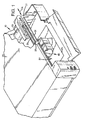
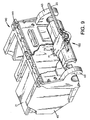
- FIG. 1 sets forth a schematic perspective view of an example of an ink jet printing device 10 in which the disclosed invention can be employed.
- the ink jet printing device includes a reciprocating print carriage that is slidably mounted on a slider rod and supports one or more print cartridges having printing elements such as ink jet nozzles.
- the print carriage is by an actuator sleeve or sub-carriage that is slidably mounted on the slider rod and pulled by an endless drive belt.
- the sub-carriage moves the print carriage via a coupling interface on the print carriage and the sub-carriage.
- the coupling interface comprises contact structures disposed on each end of the sub-carriage and an adjacent bearing support, such as a contact bump and a corresponding land.
- a further example of a coupling interface includes a tab or blade on one of the carriage and the sub-carriage that is engaged in a socket or gap in the other of the carriage and the sub-carriage.
- the ink jet printing device 10 of FIG. 1 more particularly includes a frame or chassis 21 surrounded by a housing, casing or enclosure 23, commonly made of sheet metal and/or plastic.
- a sheet of print media 25 "picked" from a stack of sheets of print media is individually fed through a print zone 27 by a suitable media handling system.
- the print media may be any type of suitable sheet material such as paper, card-stock, transparencies, coated paper, fabric, and the like.
- a carriage slider or guide rod 31 is supported by the chassis 21 to slidably support an ink jet print carriage 40 for back and forth, or reciprocating, motion across the print zone 27 along a carriage axis CA that is parallel to the longitudinal axis of the slider rod 31.
- a carriage scan axis drive motor 33 drives an endless belt 35 that is secured an to actuator sub-carriage 50 (FIG. 2) that in turn drives the print carriage 40.
- a linear encoder strip 37 is utilized to detect position of the print carriage 40 along the carriage scan axis, for example in accordance with conventional techniques.
- the print carriage 40 supports, for example, a plurality of ink jet printhead cartridges 21, and in the print zone 27, the media sheet 25 receives ink from the ink jet printhead cartridges 21.
- Each of the ink jet printhead cartridges can comprise a single color printhead cartridge or a multiple color printhead cartridge.
- each of the ink jet printhead cartridges 21 can comprise a self-contained printhead cartridge that includes one or more on-board ink reservoirs that are not coupled to remote ink reservoirs.
- each of the printhead cartridges can comprise a printhead cartridge having one or more small on-board ink reservoirs that are replenished from an "off-axis" ink supply that is separate from the printhead cartridge.
- the print zone 27 is below the ink jet printhead cartridges 21, and the printheads thereof eject ink drops downwardly.
- Ink jet printhead cartridges 21 are also commonly called "pens" by those in the art.
- the printing device of FIG. 1 can employ any number of printhead cartridges which for example can be thermal ink jet printhead cartridges.
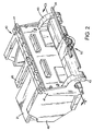
- the print carriage 40 more particularly includes a carriage chassis 41 that supports forwardly extending chutes or stalls 45 that support the printhead cartridges 21.
- Bearing supports 43 spaced apart along the carriage axis CA extend rearwardly from the carriage chassis 41 and slidably support the print carriage 40 on the slider rod 31 (FIG. 1).
- the print carriage 40 is driven by an actuator sleeve or sub-carriage 50 that is slidably mounted on the slider rod 31 between the carriage bearing supports 43 and is attached to the endless belt 35.
- the sub-carriage 50 can be generally comprised of a body or rail 51 having bearing supports 53 at the ends of the rail 51.
- the bearing supports 53 are spaced apart along the carriage axis and are slidably mounted on the slider rod 31.
- a belt hook 55 is disposed in the middle portion of the rail 51 and securely attaches the sub-carriage 50 to the endless belt 35 which pulls the sub-carriage 50 back and forth along the slider rod 31.
- the rotational position of the sub-carriage about the slider rod is maintained by the endless belt 35.
- the sub-carriage 50 is mounted on the slider rod between the carriage bearing supports 43, and thus drives the print carriage 40 by contact of an end of the sub-carriage 50 against an adjacent bearing support 43.
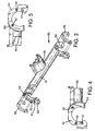
- each end of the sub-carriage 50 includes axially extending pins 52 and an axially extending rim 54 that in cooperation with an indented region 42 in the adjacent carriage bearing support 43 (as shown in FIGS. 6 and 7) retains C-shaped lubricating pads 56.
- Each end of the sub-carriage 50 further includes a contact bump or protrusion 57 that contacts an associated land 47 on the inside surface of the adjacent carriage bearing support 43 when the sub-carriage 50 is urged toward that associated planar contact surface 47.
- the contact bumps 57 extend generally along the carriage axis CA and the lands 47 are orthogonal to the carriage axis CA.
- the pins 52 and the rims 54 on the ends of the sub-carriage 50 and the indented regions 42 in the carriage bearing supports 43 adjacent the ends of the sub-carriage 50 are configured such that when the sub-carriage 50 and the carriage 40 are installed on the slider rod 31 in their proper rotational orientation about the slider rod 31, contact between the sub-carriage 50 and the carriage 40 can only be made between a contact bump 57 and the adjacent land 47.
- contact is made only between the contact bump 57 on the leading end of the sub-carriage 50 and the adjacent land 47.
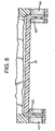
- the sub-carriage 50 is further dimensioned such that a clearance fit exists between the bumps 57 and the adjacent contact surfaces 47, as illustrated in FIG. 8. That is, the distance between the outermost points on the bumps 57 is slightly less than the distance between the lands 47 such that if one bump 57 is in contact with the adjacent land 47, the other bump is not in contact with the land adjacent thereto.
- the sub-carriage 50 can be implemented without the pins and rims for supporting lubricating pads, for example with end surfaces that are orthogonal to the slider rod and from which the contact bumps extend.
- the indented regions 47 in the carriage bearing supports 43 can be omitted so that the entire surface of the bearing support that is adjacent an end of the sub-carriage can be a continuous planar surface that would include the land 47.
- the bumps 57 and the adjacent lands 47 provide for a point contact interface by which a pushing force is advantageously applied to the carriage 40 over a very small contact area that ideally approaches a point.
- the contact structure comprised of the bumps 57 and lands 47 are preferably located such that the points of contact are on a line that is parallel to the longitudinal axis of the slider rod 31 and close to a centroid of the retarding forces to which the carriage 50 is subjected (e.g., mass and friction). That centroid is typically close to the slider rod, and the bumps 57 and lands 47 are disclosed as being adjacent to the slider rod.
- FIG. 9 schematically illustrated therein is further example of a carriage assembly in accordance with the invention.
- an ink jet print carriage 140 is pushed by a sub-carriage 150 via a "blade and gap" coupling structure.
- the sub-carriage 150 is slidably mounted on the slider rod between bearing supports 43 of the carriage 140, and includes a blade or tab 71 that extends from a body 151 of the sub-carriage into a pocket or gap 73 formed in a chassis 141 of the carriage 140 which is otherwise substantially similar to the carriage 40 of FIG. 3.
- the blade 71 and the gap 73 can employ contact bumps and lands to achieve a point contact interface between the print carriage 140 and the sub-carriage 150.
- the contacting inside edges of the gap 73 and the contacting outside edges of the blade can be convex, so as to limit contact to a very small area.
- the foregoing has been a disclosure of a print carriage assembly that affords greater design freedom as to placement of components on the print carriage, allows for a compact design, and allows for closer to optimal placement of the pushing force applied to the print carriage.
- Optimal placement of the pushing force allows the carriage to be accelerated at a higher rate, which decreases printing time, thereby improving throughput, and allows the width of the printer to be reduced since a shorter distance is required to accelerate the carriage.
- the disclosed print carriage assembly also provides for reduced material cost since the print carriage can be made smaller and since the sub-carriage is not as dimensionally critical as the carriage and thus can be made of a less expensive material.
Landscapes
- Ink Jet (AREA)
- Character Spaces And Line Spaces In Printers (AREA)
- Common Mechanisms (AREA)
Claims (11)
- Eine Druckwagenanordnung für einen Drucker, die folgende Merkmale aufweist:einen Druckwagen (40), der gleitfähig an einem Gleitstab (31) befestigt ist;einen Unterwagen (50; 150), der von dem Druckwagen getrennt und nicht fest an demselben angebracht ist und der gleitfähig an dem Gleitstab befestigt ist, wobei der Unterwagen an einem Antriebsriemen (35) zur Bewegung entlang einer Wagenachse angebracht ist; undeine Kopplungsstruktur (43, 53; 71, 73), die an dem Druckwagen und dem Unterwagen angeordnet ist, durch die der Unterwagen (50; 150) den Druckwagen (40) kontaktiv bewegt, um den Druckwagen entlang dem Gleitstab zu treiben, dadurch gekennzeichnet, dass die Kopplungsstruktur eine Punktkontaktstruktur (47, 57; 71, 73) umfasst.
- Die Druckwagenanordnung gemäß Anspruch 1, bei der:der Wagen (40) einen ersten Lagerträger (43) und einen zweiten Lagerträger (43) umfasst, die gleitfähig an dem Gleitstab (31) befestigt sind und entlang einer longitudinalen Achse des Gleitstabs beabstandet sind; undder Unterwagen (50; 150) zwischen dem ersten Lagerträger (43) und dem zweiten Lagerträger (43) angeordnet ist.
- Die Druckwagenanordnung gemäß Anspruch 2, bei der die Kopplungsstruktur den ersten Lagerträger (43) und den zweiten Lagerträger (43) und ein erstes und ein zweites Ende (53) des Unterwagens, die entlang der longitudinalen Achse voneinander beabstandet sind, zur kontaktiven Ineingriffnahme des ersten Lagerträgers und des zweiten Lagerträgers aufweist, wobei der Lagerträger (43) des Wagens und das erste und das zweite Ende (53) des Unterwagens die Punktkontaktstruktur (47; 57) umfassen.
- Die Druckwagenanordnung gemäß Anspruch 3, bei der die Punktkontaktstruktur einen Vorsprung (57) und eine Kontaktstelle (47) umfasst, die durch den Vorsprung kontaktiv in Eingriff nehmbar ist.
- Die Druckwagenanordnung gemäß Anspruch 3 oder 4, die ferner ein Schmierkissen (56) umfasst, das zwischen dem ersten Lagerträger (43) des Druckwagens und dem ersten Ende (53) des Unterwagens angeordnet ist.
- Die Druckwagenanordnung gemäß Anspruch 1 oder 2, bei der die Punktkontaktstruktur ein Blatt (71) und einen Spalt (73) umfasst.
- Ein Drucksystem, das folgende Merkmale aufweist:die Druckwagenanordnung gemäß einem der vorhergehenden Ansprüche; undein Bilderzeugungselement (21), das durch den Druckwagen (40) getragen wird.
- Das Drucksystem gemäß Anspruch 7, bei dem das Bilderzeugungselement (21) eine Tintenstrahldruckkassette aufweist.
- Das Drucksystem gemäß Anspruch 8, bei dem die Tintenstrahldruckkassette (21) entfernbar ist.
- Ein Verfahren zum Betreiben eines Druckers, das folgende Schritte aufweist:Bewegen eines Unterwagens (50, 150) entlang einem Gleitstab (31); undIneingriffbringen eines Druckwagens (40) mit dem Unterwagen, um den Druckwagen entlang dem Gleitstab zu bewegen, wobei der Schritt des Ineingriffbringens des Unterwagens (50; 150), um den Druckwagen (40) zu bewegen, den Schritt eines Bewirkens umfasst, dass der Unterwagen den Druckwagen über eine Punktkontaktschnittstelle (47, 57; 71, 73) kontaktiert.
- Das Verfahren gemäß Anspruch 10, bei dem der Schritt des Ineingriffbringens des Unterwagens (50; 150) den Schritt eines kontaktiven Schiebens des Druckwagens (40) umfasst.
Applications Claiming Priority (2)
| Application Number | Priority Date | Filing Date | Title |
|---|---|---|---|
| US477648 | 2000-01-05 | ||
| US09/477,648 US6471426B1 (en) | 2000-01-05 | 2000-01-05 | Method of propelling an inkjet printer carriage |
Publications (2)
| Publication Number | Publication Date |
|---|---|
| EP1114732A1 EP1114732A1 (de) | 2001-07-11 |
| EP1114732B1 true EP1114732B1 (de) | 2006-05-03 |
Family
ID=23896781
Family Applications (1)
| Application Number | Title | Priority Date | Filing Date |
|---|---|---|---|
| EP00311389A Expired - Lifetime EP1114732B1 (de) | 2000-01-05 | 2000-12-19 | Neues Antriebsverfahren eines Druckwagens eines Tintenstrahldruckers |
Country Status (5)
| Country | Link |
|---|---|
| US (2) | US6471426B1 (de) |
| EP (1) | EP1114732B1 (de) |
| JP (1) | JP2001219616A (de) |
| DE (1) | DE60027684T2 (de) |
| TW (1) | TW533134B (de) |
Families Citing this family (9)
| Publication number | Priority date | Publication date | Assignee | Title |
|---|---|---|---|---|
| US6648528B2 (en) * | 2001-09-28 | 2003-11-18 | Hewlett-Packard Development Company, L.P. | Stationary media mobile printing |
| US7300146B2 (en) | 2003-03-21 | 2007-11-27 | Hewlett-Packard Development Company, L.P. | Embossing using clear ink |
| US7048367B2 (en) * | 2003-04-04 | 2006-05-23 | Hewlett-Packard Development Company, L.P. | Preconditioning media for embossing |
| US6953239B2 (en) * | 2003-06-13 | 2005-10-11 | Hewlett-Packard Development Company, L.P. | Printer system and printing method |
| US7036919B2 (en) * | 2003-06-13 | 2006-05-02 | Hewlett-Packard Development Company, L.P. | Print Cartridge |
| US7364261B2 (en) * | 2004-03-10 | 2008-04-29 | Lexmark International, Inc. | Directionally dependent carrier isolator for an imaging apparatus |
| US7920289B2 (en) * | 2004-05-17 | 2011-04-05 | Hewlett-Packard Development Company, L.P. | Printing system and method |
| JP2007053419A (ja) * | 2005-08-15 | 2007-03-01 | Fuji Xerox Co Ltd | 画像形成装置 |
| JP5257596B2 (ja) * | 2008-01-15 | 2013-08-07 | セイコーエプソン株式会社 | ガイド軸の軸受装置、記録装置 |
Family Cites Families (13)
| Publication number | Priority date | Publication date | Assignee | Title |
|---|---|---|---|---|
| JPS6222376Y2 (de) | 1980-09-25 | 1987-06-06 | ||
| US4468144A (en) | 1982-06-09 | 1984-08-28 | Contitronix, Inc. | Detachable carriage assembly for printer |
| JPS5942977A (ja) | 1982-09-06 | 1984-03-09 | Alps Electric Co Ltd | サ−マルプリンタのヘツド加圧装置 |
| DE3313205C1 (de) | 1983-04-12 | 1984-10-04 | Siemens AG, 1000 Berlin und 8000 München | Vorrichtung zur Fuehrung einer Druckwerkes |
| US4613246A (en) | 1984-01-31 | 1986-09-23 | Brother Kogyo Kabushiki Kaisha | Printer with mounting structure for print head |
| US4683481A (en) | 1985-12-06 | 1987-07-28 | Hewlett-Packard Company | Thermal ink jet common-slotted ink feed printhead |
| US5044797A (en) | 1988-04-01 | 1991-09-03 | Ncr Corporation | Device for connecting a timing belt to a printhead carriage |
| US5278584A (en) | 1992-04-02 | 1994-01-11 | Hewlett-Packard Company | Ink delivery system for an inkjet printhead |
| JPH07195784A (ja) | 1993-12-28 | 1995-08-01 | Canon Inc | プリンタの駆動方法 |
| JPH09240097A (ja) * | 1996-03-08 | 1997-09-16 | Canon Inc | 走査型キャリアを備える機器およびプリント装置 |
| US6250735B1 (en) * | 1998-02-05 | 2001-06-26 | Canon Kabushiki Kaisha | Cover for print head alignment sensor |
| EP0953456A1 (de) | 1998-04-29 | 1999-11-03 | Hewlett-Packard Company | Integrierter Aufbau für hin und her geführte Tintenkassetten mit integrierten Lagern |
| US6244765B1 (en) * | 1999-06-30 | 2001-06-12 | Hewlett-Packard Company | Vibration isolating attachment system for inkjet carriages |
-
2000
- 2000-01-05 US US09/477,648 patent/US6471426B1/en not_active Expired - Fee Related
- 2000-12-19 EP EP00311389A patent/EP1114732B1/de not_active Expired - Lifetime
- 2000-12-19 DE DE60027684T patent/DE60027684T2/de not_active Expired - Fee Related
- 2000-12-27 TW TW089122484A patent/TW533134B/zh not_active IP Right Cessation
- 2000-12-28 JP JP2000400235A patent/JP2001219616A/ja not_active Withdrawn
-
2002
- 2002-06-25 US US10/179,129 patent/US6692169B2/en not_active Expired - Fee Related
Also Published As
| Publication number | Publication date |
|---|---|
| US6692169B2 (en) | 2004-02-17 |
| US6471426B1 (en) | 2002-10-29 |
| JP2001219616A (ja) | 2001-08-14 |
| EP1114732A1 (de) | 2001-07-11 |
| DE60027684D1 (de) | 2006-06-08 |
| DE60027684T2 (de) | 2006-12-07 |
| TW533134B (en) | 2003-05-21 |
| US20020168207A1 (en) | 2002-11-14 |
Similar Documents
| Publication | Publication Date | Title |
|---|---|---|
| US4774529A (en) | Repositionable marking head for increasing printing speed | |
| EP1145855B1 (de) | Druckkopf-Substrat mit Tintentropfenerzeugern gruppiert abwechselnd an einer und beiden Seiten der Tintenzufuhrkanäle | |
| EP0827839A1 (de) | Mechanische Vorrichtung für Auslösungsverdoppelung | |
| JPH05212872A (ja) | インクジェットプリントヘッドのノズルキャップ装置 | |
| US6659586B2 (en) | System and method for servicing non-scanning printhead | |
| EP0921006A1 (de) | Druckeranordnung | |
| EP0664221A2 (de) | Seriendrucker mit offenem Regelkreis | |
| EP1114732B1 (de) | Neues Antriebsverfahren eines Druckwagens eines Tintenstrahldruckers | |
| US6837635B1 (en) | Inkjet apparatus and method for controlling undulation on media | |
| US5971641A (en) | Carriage driven tray lowering device for an ink jet printer | |
| EP1004440A3 (de) | Vorrichtung zum Tintenstrahldrucken mit mehreren Zonen | |
| EP1145856B1 (de) | Druckkopf mit unterschiedlichem Düsenabstand zwischen Düsenreihen | |
| US6805427B2 (en) | Liquid ejecting apparatus | |
| US6340221B1 (en) | Ink jet print carriage drive system that applies drive force at location displaced from drive belt | |
| US6318827B1 (en) | Method of improving print quality by selectively changing print direction | |
| US20020164191A1 (en) | Apparatus and method for transporting print media through a printzone of a printing device | |
| EP1145854B1 (de) | Druckkopf-Substrat mit Tintentropfenerzeugern aufgeteilt in Gruppen die beide Seitenkanten eines Tintenzuführkanals umfassen | |
| JPH0939256A (ja) | インクジェットプリンタ | |
| US20020180829A1 (en) | Carriage dam | |
| JPH0671973A (ja) | インクジェット記録装置 | |
| JPH01241448A (ja) | インクジェット式記録装置 | |
| JPH06262816A (ja) | 記録装置 | |
| JPH05212864A (ja) | インクジェット式記録装置 | |
| JP2004160945A (ja) | インクジェット記録装置 | |
| JP2004042483A (ja) | インクジェット記録装置 |
Legal Events
| Date | Code | Title | Description |
|---|---|---|---|
| PUAI | Public reference made under article 153(3) epc to a published international application that has entered the european phase |
Free format text: ORIGINAL CODE: 0009012 |
|
| AK | Designated contracting states |
Kind code of ref document: A1 Designated state(s): DE FR GB |
|
| AX | Request for extension of the european patent |
Free format text: AL;LT;LV;MK;RO;SI |
|
| 17P | Request for examination filed |
Effective date: 20011217 |
|
| AKX | Designation fees paid |
Free format text: DE FR GB |
|
| 17Q | First examination report despatched |
Effective date: 20040510 |
|
| GRAP | Despatch of communication of intention to grant a patent |
Free format text: ORIGINAL CODE: EPIDOSNIGR1 |
|
| GRAS | Grant fee paid |
Free format text: ORIGINAL CODE: EPIDOSNIGR3 |
|
| GRAA | (expected) grant |
Free format text: ORIGINAL CODE: 0009210 |
|
| AK | Designated contracting states |
Kind code of ref document: B1 Designated state(s): DE FR GB |
|
| REG | Reference to a national code |
Ref country code: GB Ref legal event code: FG4D |
|
| REF | Corresponds to: |
Ref document number: 60027684 Country of ref document: DE Date of ref document: 20060608 Kind code of ref document: P |
|
| ET | Fr: translation filed | ||
| PLBE | No opposition filed within time limit |
Free format text: ORIGINAL CODE: 0009261 |
|
| STAA | Information on the status of an ep patent application or granted ep patent |
Free format text: STATUS: NO OPPOSITION FILED WITHIN TIME LIMIT |
|
| 26N | No opposition filed |
Effective date: 20070206 |
|
| PGFP | Annual fee paid to national office [announced via postgrant information from national office to epo] |
Ref country code: GB Payment date: 20071227 Year of fee payment: 8 |
|
| PGFP | Annual fee paid to national office [announced via postgrant information from national office to epo] |
Ref country code: DE Payment date: 20080131 Year of fee payment: 8 |
|
| PGFP | Annual fee paid to national office [announced via postgrant information from national office to epo] |
Ref country code: FR Payment date: 20071217 Year of fee payment: 8 |
|
| GBPC | Gb: european patent ceased through non-payment of renewal fee |
Effective date: 20081219 |
|
| REG | Reference to a national code |
Ref country code: FR Ref legal event code: ST Effective date: 20090831 |
|
| PG25 | Lapsed in a contracting state [announced via postgrant information from national office to epo] |
Ref country code: DE Free format text: LAPSE BECAUSE OF NON-PAYMENT OF DUE FEES Effective date: 20090701 |
|
| PG25 | Lapsed in a contracting state [announced via postgrant information from national office to epo] |
Ref country code: GB Free format text: LAPSE BECAUSE OF NON-PAYMENT OF DUE FEES Effective date: 20081219 |
|
| PG25 | Lapsed in a contracting state [announced via postgrant information from national office to epo] |
Ref country code: FR Free format text: LAPSE BECAUSE OF NON-PAYMENT OF DUE FEES Effective date: 20081231 |