EP0979740B1 - Instrument d'écriture - Google Patents
Instrument d'écriture Download PDFInfo
- Publication number
- EP0979740B1 EP0979740B1 EP99250228A EP99250228A EP0979740B1 EP 0979740 B1 EP0979740 B1 EP 0979740B1 EP 99250228 A EP99250228 A EP 99250228A EP 99250228 A EP99250228 A EP 99250228A EP 0979740 B1 EP0979740 B1 EP 0979740B1
- Authority
- EP
- European Patent Office
- Prior art keywords
- clip
- shaft
- fastening steps
- fastening
- writing implement
- Prior art date
- Legal status (The legal status is an assumption and is not a legal conclusion. Google has not performed a legal analysis and makes no representation as to the accuracy of the status listed.)
- Expired - Lifetime
Links
- 230000006835 compression Effects 0.000 claims description 5
- 238000007906 compression Methods 0.000 claims description 5
- 238000006073 displacement reaction Methods 0.000 claims description 2
- 238000004026 adhesive bonding Methods 0.000 description 2
- 230000005489 elastic deformation Effects 0.000 description 2
- 238000003825 pressing Methods 0.000 description 2
- 239000000853 adhesive Substances 0.000 description 1
- 230000001070 adhesive effect Effects 0.000 description 1
- 230000000694 effects Effects 0.000 description 1
- 238000003780 insertion Methods 0.000 description 1
- 230000037431 insertion Effects 0.000 description 1
- 238000004519 manufacturing process Methods 0.000 description 1
- 239000002184 metal Substances 0.000 description 1
- 230000002093 peripheral effect Effects 0.000 description 1
- 230000007704 transition Effects 0.000 description 1
- 238000003466 welding Methods 0.000 description 1
Images


Classifications
-
- B—PERFORMING OPERATIONS; TRANSPORTING
- B43—WRITING OR DRAWING IMPLEMENTS; BUREAU ACCESSORIES
- B43K—IMPLEMENTS FOR WRITING OR DRAWING
- B43K23/00—Holders or connectors for writing implements; Means for protecting the writing-points
- B43K23/08—Protecting means, e.g. caps
- B43K23/12—Protecting means, e.g. caps for pens
- B43K23/126—Protecting means, e.g. caps for pens with clips
-
- B—PERFORMING OPERATIONS; TRANSPORTING
- B43—WRITING OR DRAWING IMPLEMENTS; BUREAU ACCESSORIES
- B43K—IMPLEMENTS FOR WRITING OR DRAWING
- B43K23/00—Holders or connectors for writing implements; Means for protecting the writing-points
- B43K23/08—Protecting means, e.g. caps
- B43K23/12—Protecting means, e.g. caps for pens
- B43K23/128—Protecting means, e.g. caps for pens with spring means
-
- B—PERFORMING OPERATIONS; TRANSPORTING
- B43—WRITING OR DRAWING IMPLEMENTS; BUREAU ACCESSORIES
- B43K—IMPLEMENTS FOR WRITING OR DRAWING
- B43K25/00—Attaching writing implements to wearing apparel or objects involving constructional changes of the implements
- B43K25/02—Clips
- B43K25/022—Clips attached to a pen cap
Definitions
- the invention relates to a writing instrument with a clip with a central section, at the front end of a clamping section and a fastening area at the rear end area thereof is provided, the two are substantially parallel to each other and in the direction of the longitudinal extent of the central section extending fastening webs that limits pivotally connected to a shaft part of the writing instrument are, the pivoting of the mounting webs and thus the Relocation of the clamping section of the clip in a further from Shaft part removed position against spring force.
- the clip can be passed through appropriate application of force from its snap bracket to the Loosen rib-shaped webs of the shaft part and thus from Disconnect the writing instrument. There is therefore a risk that the clip is lost in use.
- to hold the Clips on the shaft part are rib-shaped webs, so that the shape for the manufacture of the shaft part accordingly must be elaborately trained.
- a writing instrument is the beginning mentioned type designed according to the invention such that the Shaft part made of two interconnected shaft sections is formed, between them a receiving opening for the Fastening webs of the clip form the fastening webs sets against movement in the axial direction of the shaft part and the axially extending boundary edges at least with partial areas rest on the outer surfaces of the fastening webs that the fastening webs on their rear, radially inner Ends have rearward-extending retaining projections, which engages with a groove open to the front in the rear Shaft section stand, the radial width of the groove is larger than the radial extension of the retaining projections, and that at the axially front ends of the fastening webs forward extending positioning projections are provided, which in the non-pivoted position at a radial distance from the surrounding wall of the shaft part.
- the clip is thus in the writing instrument according to the invention by means of the holding and provided on the fastening webs Positioning projections secured against removal in the Receiving opening of the mounting web held, the Insertion in the receiving opening with separate Shaft sections carried out afterwards, for example by Gluing or ultrasonic welding, can be joined together.
- the intervention defining the position of the clip makes it possible the retaining projections with the groove open towards the front in the rear Shaft section and the radial distance between the positioning projections a pivoting of the surrounding wall of the shaft part Clips around an axis that is roughly in the area of the retaining projections lies, i.e. the clamping section of the clip can be in one position brought further away from the surface of the shaft part become.
- the clip preferably has a distance from the area of the fastening webs backward extending support portion.
- This Support portion can form a spring arm on the outer surface of the Fit the shaft part and thus when pivoting the clip to lift its clamping section from the outer surface of the Shaft part are elastically deformed. The resulting one Spring action guides the clamping section when the clip is released back to its original position.
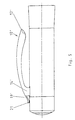
- the cap shown in Figures 1 to 4 for a Writing instrument has a cup-shaped shaft or housing part 1, that from a shaft section widening towards the open end 2 and a cup-shaped shaft section 3, which inserted with its front end into the shaft section 2 and is connected to this for example by gluing.
- the Shank section 3 forms in the central region of its cylindrical Section an outer circumferential groove 5, which is in the rear continues a circumferential groove 6 open to the front.
- Radial outside the groove 6 is an annular shoulder on the shaft section 3 formed with which the rear end of the shaft portion 2 in Engagement is so that there is between the outer surfaces of the two Shaft sections 2, 3 results in a smooth, smooth transition.
- the shaft section 2 has one at its rear end recess open to the rear, which in the assembled state of the Shaft sections 2 and 3, shown in Figures 1 to 4 together with the shaft section 3 is a receiving opening 7 forms.
- shaft part 1 In the shaft part 1 is in the usual way for writing instruments cup-shaped seal 4 used. This covers one in Shank section 3 formed through opening 8, which itself in the area of the front end of the receiving opening 7 and something is located radially further inside.
- the clip 10 connected to the shaft part 1, which is usually consists of metal, has a curved central portion 11 the front end of which is formed a clamping section 12.
- a clamping section 12 in the the rear end region of the clip 10 are two parallel fastening webs 13, 14 formed, which are spaced apart are located and the retaining projections at their radially inner rear ends 15, 16 have.
- the fastening webs 13, 14 are positioning projections 17, 18 available.
- the clip 10 has from its front, the clamping section 12 forming area to its rear end area, in which the fastening webs 13, 14 are located, a U-shaped Cross section, the fastening webs 13, 14 parts form the leg of the U. This results in a pronounced Dimensional stability.
- About the through the webs 13, 14th formed end region extends backwards support section 19 formed in one piece with the rest of the clip, which is essentially rectangular in cross section, that is does not have a U-shaped cross section.
- the clip 10 is mounted in the shaft part 1 in that it separate shaft sections 2, 3 with its rear holding projections 15, 16 in the open, circumferential groove 6 of the Shaft section 3 is used. Then the shaft section 3 inserted with the clip 10 in the shaft section 2 and made the adhesive connection. In this situation, the in Figure 2 is shown, the holding projections 15, 16 of the fastening webs 13, 14 in the groove 6, the radial Extension is greater than the radial extension of the holding projections 15, 16.
- the Clip 10 that prevents circumferential displacement by engagement its fastening webs 13, 14 with the axially extending Boundary surfaces of the receiving opening 7 is not positioned be removed from the receiving opening 7, because even if he slightly from the position according to FIG. until it stops the front edges of its fastening projections 13, 14 on the front peripheral wall of the receiving opening 7 moved forward is, there are the holding projections 15, 16 of the fastening webs 13, 14 still in the groove 6 of the rear shaft section 3, while the positioning projections 17, 18 before the front end of the receiving opening 7 lying wall area of the reach under the front shaft section 2.
- the support section lies 19 with its rear end area on the outer surface of the rear shaft section 3 and causes under lighter elastic deformation pressing the clamping portion 12 of the Clips 10 to the outer surface of the front shaft section 2. If the user removes the clamping portion 12 of the clip 10 from the The outer surface of the front shaft section 2 lifts off, approximately by one To be inserted into a pocket, there is a pivoting the fastening webs 13, 14 from their shown in Figure 2 Position in which the positioning projections 17, 18 are somewhat radial be moved outside, because of the distance between them Positioning tabs and the surrounding wall of the front Shaft section 2 is easily possible while the Fastening webs 13, 14 in the region of the holding projections 15, 16 on the radially inner wall of the groove 6 or the circumferential groove 5 in rear shaft section 3 are supported. At this Pivoting the support arm 19 is even more elastic deforms and thus generates an increased restoring force through which the clamping section 12 towards the outer surface of the shaft section 2 is charged.
- FIGS Figures 1 to 4 differs from that of Figures 1 to 4 only by forming the support section of the clip while the cap forming the shaft part has the same shape as in FIGS Figures 1 to 4 has and therefore not again in detail is shown and / or explained.
- the clip 10 ' one of the fastening webs 13 ', 14' to the rear extending support arm 19 ', which in this case also a Has a U-shaped cross section and forms a receiving opening 20, in which the outer end of a compression spring 21 is supported.
- the inner end of the compression spring 21 lies on the outer surface of the Shaft part 1, so that in accordance with the embodiment Figures 1 to 4 by the elastic deformability of the support arm 19 generated spring force for pressing the clamping section 12th of the clip 10 in the exemplary embodiment according to FIGS. 5 and 6 is generated by a separate compression spring 21 which on a essentially non-elastically deformable support arm 19 'of Clips 10 'works.
Landscapes
- Clips For Writing Implements (AREA)
- Pens And Brushes (AREA)
Claims (4)
- Instrument d'écriture comprenant un clip (10 ; 10') avec une section centrale (11 ; 11'), sur l'extrémité avant de laquelle est prévue une section de serrage (12 ; 12') et sur la zone extrême arrière de laquelle est prévue une zone de fixation, qui présente deux traverses de fixation (13, 14 ; 13', 14') s'étendant de façon essentiellement parallèle entre elles et en direction de l'extension longitudinale de la section centrale (11 ; 11'), et qui sont assemblées avec une possibilité de pivotement limitée avec une partie de manche (1) de l'instrument d'écriture, le pivotement des traverses de fixation (13, 14 ; 13', 14'), et ainsi le déplacement de la section de serrage (12 ; 12') du clip (10 ; 10'), dans une position plus écartée de la partie de manche (1) étant assurés contre une force de ressort, caractérisé en ce que la partie de manche (1) est formée de deux sections de manche (2, 3) assemblées entre elles, qui forment entre elles une ouverture de réception (7) pour les traverses de fixation (13, 14) du clip (10), ouverture qui fixe les traverses de fixation (13, 14) contre un déplacement dans la direction axiale de la partie de manche (1) et dont des bords de délimitation axiaux s'appliquent au moins par des zones partielles sur les surfaces extérieures des traverses de fixation (13, 14), en ce que les traverses de fixation (13, 14 ; 13', 14') présentent sur leurs extrémités arrière radiales internes des saillies de retenue (15, 16 ; 15') s'étendant vers l'arrière, qui sont en prise avec une rainure (6) ouverte vers l'avant dans la section de manche arrière (3), la largeur radiale de la rainure (6) étant supérieure à l'extension radiale des saillies de retenue (15, 16 ; 16'), et en ce que des saillies de positionnement (17, 18 ; 17') s'étendant vers l'avant, prévues sur les extrémités avant axiales des traverses de fixation (13, 14 ; 13'), se situent au moins dans la position de non pivotement à distance radiale de la paroi d'enveloppe de la partie de manche (1).
- Instrument d'écriture suivant la revendication 1, caractérisé en ce que le clip (10 ; 10') présente une section d'appui (19 ; 19') s'étendant vers l'arrière à partir de la zone des traverses de fixation (13, 14 ; 13', 14').
- Instrument d'écriture suivant la revendication 2, caractérisé en ce que la section d'appui (19) s'applique sur la surface extérieure de la section de manche (3) en formant un bras de ressort.
- Instrument d'écriture suivant la revendication 2, caractérisé en ce qu'un ressort de compression (21) est disposé entre la section d'appui (19') et la surface extérieure de la section de manche (3).
Applications Claiming Priority (2)
| Application Number | Priority Date | Filing Date | Title |
|---|---|---|---|
| DE29814815U DE29814815U1 (de) | 1998-08-11 | 1998-08-11 | Schreibgerät |
| DE29814815U | 1998-08-11 |
Publications (2)
| Publication Number | Publication Date |
|---|---|
| EP0979740A1 EP0979740A1 (fr) | 2000-02-16 |
| EP0979740B1 true EP0979740B1 (fr) | 2003-04-23 |
Family
ID=8061444
Family Applications (1)
| Application Number | Title | Priority Date | Filing Date |
|---|---|---|---|
| EP99250228A Expired - Lifetime EP0979740B1 (fr) | 1998-08-11 | 1999-07-09 | Instrument d'écriture |
Country Status (5)
| Country | Link |
|---|---|
| EP (1) | EP0979740B1 (fr) |
| JP (1) | JP2000052687A (fr) |
| AT (1) | ATE238169T1 (fr) |
| DE (2) | DE29814815U1 (fr) |
| ES (1) | ES2192019T3 (fr) |
Cited By (1)
| Publication number | Priority date | Publication date | Assignee | Title |
|---|---|---|---|---|
| US9662927B2 (en) | 2012-03-16 | 2017-05-30 | SOCIéTé BIC | Structure for mounting a clip for a writing implement |
Families Citing this family (2)
| Publication number | Priority date | Publication date | Assignee | Title |
|---|---|---|---|---|
| DE20018812U1 (de) * | 2000-11-03 | 2002-03-07 | Gottlieb Roll GmbH & Co. KG, 55743 Idar-Oberstein | Halteclip für Schreibgeräte |
| JP4625706B2 (ja) * | 2005-03-04 | 2011-02-02 | 株式会社パイロットコーポレーション | クリップ部材を有する筆記具 |
Family Cites Families (6)
| Publication number | Priority date | Publication date | Assignee | Title |
|---|---|---|---|---|
| FR947066A (fr) * | 1947-05-14 | 1949-06-22 | Clip pour stylographes, porte-mines et objets analogues | |
| FR970151A (fr) * | 1948-08-03 | 1951-01-02 | Agrafe de sûreté, notamment pour capuchon de stylographe | |
| DE2531078A1 (de) * | 1975-07-11 | 1977-01-27 | Merz & Krell | Kliphalterung an dem schaft oder der schutzkappe eines schreibgeraets |
| DE7719280U1 (de) | 1977-06-20 | 1977-10-13 | Fa. Gottlieb Roll, 6580 Idar-Oberstein | Halteklip-Befestigungsanordnung an Schreibgeräten |
| US4837900A (en) * | 1988-04-18 | 1989-06-13 | A.T. Cross Company | Pocket Clip assembly and assembly method |
| FR2647393A1 (fr) * | 1989-05-29 | 1990-11-30 | Cartier Int Bv | Stylo ou objet analogue a agrafe perfectionnee |
-
1998
- 1998-08-11 DE DE29814815U patent/DE29814815U1/de not_active Expired - Lifetime
-
1999
- 1999-07-09 DE DE59905150T patent/DE59905150D1/de not_active Expired - Fee Related
- 1999-07-09 ES ES99250228T patent/ES2192019T3/es not_active Expired - Lifetime
- 1999-07-09 AT AT99250228T patent/ATE238169T1/de not_active IP Right Cessation
- 1999-07-09 EP EP99250228A patent/EP0979740B1/fr not_active Expired - Lifetime
- 1999-08-06 JP JP11223160A patent/JP2000052687A/ja active Pending
Cited By (1)
| Publication number | Priority date | Publication date | Assignee | Title |
|---|---|---|---|---|
| US9662927B2 (en) | 2012-03-16 | 2017-05-30 | SOCIéTé BIC | Structure for mounting a clip for a writing implement |
Also Published As
| Publication number | Publication date |
|---|---|
| ATE238169T1 (de) | 2003-05-15 |
| DE29814815U1 (de) | 1998-10-15 |
| EP0979740A1 (fr) | 2000-02-16 |
| ES2192019T3 (es) | 2003-09-16 |
| JP2000052687A (ja) | 2000-02-22 |
| DE59905150D1 (de) | 2003-05-28 |
Similar Documents
| Publication | Publication Date | Title |
|---|---|---|
| DE60206570T2 (de) | Schwenkbolzenverbindung zwischen zwei Teilen | |
| DE29614023U1 (de) | Computertaste | |
| DE2811398B1 (de) | Schere | |
| AT2249U1 (de) | Handstempel mit selbstfärbeeinrichtung | |
| WO1996008981A1 (fr) | Bague a plusieurs parties | |
| EP0979740B1 (fr) | Instrument d'écriture | |
| DE69411534T2 (de) | Versenkbarer Drehknebel | |
| DE3603876C2 (fr) | ||
| DE2604325C3 (de) | Wischvorrichtung für Scheiben von Kraftfahrzeugen | |
| DE19823894C1 (de) | Schnappscheibenschalter mit Befestigungselement | |
| DE102019130312A1 (de) | Einbaueinheit | |
| DE2756835C2 (fr) | ||
| DE2550544C3 (de) | Lager, insbesondere Schwenklager für Fahrzeugsonnenblenden | |
| DE8002883U1 (de) | Kunststoff-Clip zur Befestigung von Verkleidungen in Kraftfahrzeugen o.dgl | |
| DE102006059096B4 (de) | Baugruppe zur fahrzeugseitigen Befestigung eines Gurtschlosses | |
| DE2813169B1 (de) | Webschaft | |
| DE2949042A1 (de) | Befestigungsanordnung fuer einen fahrzeugrueckblickspiegel | |
| DE2608605C3 (de) | Wischvorrichtung für Scheiben von Kraftfahrzeugen | |
| DE2531613A1 (de) | Elastisches gelenk, insbesondere fuer schubstangen von scheibenwischern | |
| DE9402494U1 (de) | Hülsenförmiger Schreibgeräteteil aus Kunststoff mit Halteklip | |
| DE102019102845B4 (de) | Zwei elastische Ringkörper aufweisende Drehachsenanordnung für eine Lenkrolle | |
| DE4117565C2 (de) | Handschreibgerät mit Halteklipp | |
| EP1747941A2 (fr) | Support de capteur pour fixer un capteur sur une partie de véhicule automobile | |
| EP0596237A1 (fr) | Frein sur jante de bicyclette | |
| DE102017005506A1 (de) | Verriegelungsvorrichtung einer Betätigungsstange zu einem Fahrzeugpedal eines Fahrzeuges |
Legal Events
| Date | Code | Title | Description |
|---|---|---|---|
| PUAI | Public reference made under article 153(3) epc to a published international application that has entered the european phase |
Free format text: ORIGINAL CODE: 0009012 |
|
| AK | Designated contracting states |
Kind code of ref document: A1 Designated state(s): AT BE CH CY DE DK ES FI FR GB GR IE IT LI LU MC NL PT SE |
|
| AX | Request for extension of the european patent |
Free format text: AL;LT;LV;MK;RO;SI |
|
| 17P | Request for examination filed |
Effective date: 20000703 |
|
| AKX | Designation fees paid |
Free format text: AT BE CH CY DE DK ES FI FR GB GR IE IT LI LU MC NL PT SE |
|
| GRAH | Despatch of communication of intention to grant a patent |
Free format text: ORIGINAL CODE: EPIDOS IGRA |
|
| GRAH | Despatch of communication of intention to grant a patent |
Free format text: ORIGINAL CODE: EPIDOS IGRA |
|
| GRAA | (expected) grant |
Free format text: ORIGINAL CODE: 0009210 |
|
| RAP1 | Party data changed (applicant data changed or rights of an application transferred) |
Owner name: SANFORD GMBH |
|
| AK | Designated contracting states |
Designated state(s): AT BE CH CY DE DK ES FI FR GB GR IE IT LI LU MC NL PT SE |
|
| PG25 | Lapsed in a contracting state [announced via postgrant information from national office to epo] |
Ref country code: NL Free format text: LAPSE BECAUSE OF FAILURE TO SUBMIT A TRANSLATION OF THE DESCRIPTION OR TO PAY THE FEE WITHIN THE PRESCRIBED TIME-LIMIT Effective date: 20030423 Ref country code: IE Free format text: LAPSE BECAUSE OF NON-PAYMENT OF DUE FEES Effective date: 20030423 Ref country code: FI Free format text: LAPSE BECAUSE OF FAILURE TO SUBMIT A TRANSLATION OF THE DESCRIPTION OR TO PAY THE FEE WITHIN THE PRESCRIBED TIME-LIMIT Effective date: 20030423 |
|
| REG | Reference to a national code |
Ref country code: GB Ref legal event code: FG4D Free format text: NOT ENGLISH |
|
| REG | Reference to a national code |
Ref country code: CH Ref legal event code: NV Representative=s name: ISLER & PEDRAZZINI AG Ref country code: CH Ref legal event code: EP |
|
| GBT | Gb: translation of ep patent filed (gb section 77(6)(a)/1977) |
Effective date: 20030423 |
|
| REF | Corresponds to: |
Ref document number: 59905150 Country of ref document: DE Date of ref document: 20030528 Kind code of ref document: P |
|
| REG | Reference to a national code |
Ref country code: IE Ref legal event code: FG4D Free format text: GERMAN |
|
| PG25 | Lapsed in a contracting state [announced via postgrant information from national office to epo] |
Ref country code: LU Free format text: LAPSE BECAUSE OF NON-PAYMENT OF DUE FEES Effective date: 20030709 Ref country code: CY Free format text: LAPSE BECAUSE OF FAILURE TO SUBMIT A TRANSLATION OF THE DESCRIPTION OR TO PAY THE FEE WITHIN THE PRESCRIBED TIME-LIMIT Effective date: 20030709 |
|
| PG25 | Lapsed in a contracting state [announced via postgrant information from national office to epo] |
Ref country code: SE Free format text: LAPSE BECAUSE OF FAILURE TO SUBMIT A TRANSLATION OF THE DESCRIPTION OR TO PAY THE FEE WITHIN THE PRESCRIBED TIME-LIMIT Effective date: 20030723 Ref country code: PT Free format text: LAPSE BECAUSE OF FAILURE TO SUBMIT A TRANSLATION OF THE DESCRIPTION OR TO PAY THE FEE WITHIN THE PRESCRIBED TIME-LIMIT Effective date: 20030723 Ref country code: GR Free format text: LAPSE BECAUSE OF FAILURE TO SUBMIT A TRANSLATION OF THE DESCRIPTION OR TO PAY THE FEE WITHIN THE PRESCRIBED TIME-LIMIT Effective date: 20030723 Ref country code: DK Free format text: LAPSE BECAUSE OF FAILURE TO SUBMIT A TRANSLATION OF THE DESCRIPTION OR TO PAY THE FEE WITHIN THE PRESCRIBED TIME-LIMIT Effective date: 20030723 |
|
| PG25 | Lapsed in a contracting state [announced via postgrant information from national office to epo] |
Ref country code: MC Free format text: LAPSE BECAUSE OF NON-PAYMENT OF DUE FEES Effective date: 20030731 |
|
| REG | Reference to a national code |
Ref country code: ES Ref legal event code: FG2A Ref document number: 2192019 Country of ref document: ES Kind code of ref document: T3 |
|
| NLV1 | Nl: lapsed or annulled due to failure to fulfill the requirements of art. 29p and 29m of the patents act | ||
| REG | Reference to a national code |
Ref country code: IE Ref legal event code: FD4D Ref document number: 0979740E Country of ref document: IE |
|
| ET | Fr: translation filed | ||
| PLBE | No opposition filed within time limit |
Free format text: ORIGINAL CODE: 0009261 |
|
| STAA | Information on the status of an ep patent application or granted ep patent |
Free format text: STATUS: NO OPPOSITION FILED WITHIN TIME LIMIT |
|
| 26N | No opposition filed |
Effective date: 20040126 |
|
| PGFP | Annual fee paid to national office [announced via postgrant information from national office to epo] |
Ref country code: ES Payment date: 20070726 Year of fee payment: 9 |
|
| PGFP | Annual fee paid to national office [announced via postgrant information from national office to epo] |
Ref country code: DE Payment date: 20070831 Year of fee payment: 9 |
|
| REG | Reference to a national code |
Ref country code: CH Ref legal event code: PCAR Free format text: ISLER & PEDRAZZINI AG;POSTFACH 1772;8027 ZUERICH (CH) |
|
| PGFP | Annual fee paid to national office [announced via postgrant information from national office to epo] |
Ref country code: CH Payment date: 20070730 Year of fee payment: 9 Ref country code: AT Payment date: 20070620 Year of fee payment: 9 |
|
| PGFP | Annual fee paid to national office [announced via postgrant information from national office to epo] |
Ref country code: GB Payment date: 20070727 Year of fee payment: 9 |
|
| PGFP | Annual fee paid to national office [announced via postgrant information from national office to epo] |
Ref country code: IT Payment date: 20070726 Year of fee payment: 9 Ref country code: BE Payment date: 20070816 Year of fee payment: 9 |
|
| PGFP | Annual fee paid to national office [announced via postgrant information from national office to epo] |
Ref country code: FR Payment date: 20070717 Year of fee payment: 9 |
|
| REG | Reference to a national code |
Ref country code: CH Ref legal event code: PL |
|
| GBPC | Gb: european patent ceased through non-payment of renewal fee |
Effective date: 20080709 |
|
| PG25 | Lapsed in a contracting state [announced via postgrant information from national office to epo] |
Ref country code: DE Free format text: LAPSE BECAUSE OF NON-PAYMENT OF DUE FEES Effective date: 20090203 Ref country code: AT Free format text: LAPSE BECAUSE OF NON-PAYMENT OF DUE FEES Effective date: 20080709 |
|
| REG | Reference to a national code |
Ref country code: FR Ref legal event code: ST Effective date: 20090331 |
|
| PG25 | Lapsed in a contracting state [announced via postgrant information from national office to epo] |
Ref country code: LI Free format text: LAPSE BECAUSE OF NON-PAYMENT OF DUE FEES Effective date: 20080731 Ref country code: GB Free format text: LAPSE BECAUSE OF NON-PAYMENT OF DUE FEES Effective date: 20080709 Ref country code: CH Free format text: LAPSE BECAUSE OF NON-PAYMENT OF DUE FEES Effective date: 20080731 |
|
| PG25 | Lapsed in a contracting state [announced via postgrant information from national office to epo] |
Ref country code: IT Free format text: LAPSE BECAUSE OF NON-PAYMENT OF DUE FEES Effective date: 20080709 Ref country code: FR Free format text: LAPSE BECAUSE OF NON-PAYMENT OF DUE FEES Effective date: 20080731 |
|
| REG | Reference to a national code |
Ref country code: ES Ref legal event code: FD2A Effective date: 20080710 |
|
| PG25 | Lapsed in a contracting state [announced via postgrant information from national office to epo] |
Ref country code: ES Free format text: LAPSE BECAUSE OF NON-PAYMENT OF DUE FEES Effective date: 20080710 |
|
| PG25 | Lapsed in a contracting state [announced via postgrant information from national office to epo] |
Ref country code: BE Free format text: LAPSE BECAUSE OF NON-PAYMENT OF DUE FEES Effective date: 20080731 |