EP0979155B1 - Outil de coupe - Google Patents
Outil de coupe Download PDFInfo
- Publication number
- EP0979155B1 EP0979155B1 EP98920788A EP98920788A EP0979155B1 EP 0979155 B1 EP0979155 B1 EP 0979155B1 EP 98920788 A EP98920788 A EP 98920788A EP 98920788 A EP98920788 A EP 98920788A EP 0979155 B1 EP0979155 B1 EP 0979155B1
- Authority
- EP
- European Patent Office
- Prior art keywords
- cooling medium
- tool
- male part
- channel
- section
- Prior art date
- Legal status (The legal status is an assumption and is not a legal conclusion. Google has not performed a legal analysis and makes no representation as to the accuracy of the status listed.)
- Expired - Lifetime
Links
Images


Classifications
-
- B—PERFORMING OPERATIONS; TRANSPORTING
- B23—MACHINE TOOLS; METAL-WORKING NOT OTHERWISE PROVIDED FOR
- B23Q—DETAILS, COMPONENTS, OR ACCESSORIES FOR MACHINE TOOLS, e.g. ARRANGEMENTS FOR COPYING OR CONTROLLING; MACHINE TOOLS IN GENERAL CHARACTERISED BY THE CONSTRUCTION OF PARTICULAR DETAILS OR COMPONENTS; COMBINATIONS OR ASSOCIATIONS OF METAL-WORKING MACHINES, NOT DIRECTED TO A PARTICULAR RESULT
- B23Q11/00—Accessories fitted to machine tools for keeping tools or parts of the machine in good working condition or for cooling work; Safety devices specially combined with or arranged in, or specially adapted for use in connection with, machine tools
- B23Q11/10—Arrangements for cooling or lubricating tools or work
- B23Q11/1084—Arrangements for cooling or lubricating tools or work specially adapted for being fitted to different kinds of machines
-
- B—PERFORMING OPERATIONS; TRANSPORTING
- B23—MACHINE TOOLS; METAL-WORKING NOT OTHERWISE PROVIDED FOR
- B23B—TURNING; BORING
- B23B27/00—Tools for turning or boring machines; Tools of a similar kind in general; Accessories therefor
- B23B27/10—Cutting tools with special provision for cooling
-
- B—PERFORMING OPERATIONS; TRANSPORTING
- B23—MACHINE TOOLS; METAL-WORKING NOT OTHERWISE PROVIDED FOR
- B23Q—DETAILS, COMPONENTS, OR ACCESSORIES FOR MACHINE TOOLS, e.g. ARRANGEMENTS FOR COPYING OR CONTROLLING; MACHINE TOOLS IN GENERAL CHARACTERISED BY THE CONSTRUCTION OF PARTICULAR DETAILS OR COMPONENTS; COMBINATIONS OR ASSOCIATIONS OF METAL-WORKING MACHINES, NOT DIRECTED TO A PARTICULAR RESULT
- B23Q11/00—Accessories fitted to machine tools for keeping tools or parts of the machine in good working condition or for cooling work; Safety devices specially combined with or arranged in, or specially adapted for use in connection with, machine tools
- B23Q11/10—Arrangements for cooling or lubricating tools or work
-
- B—PERFORMING OPERATIONS; TRANSPORTING
- B23—MACHINE TOOLS; METAL-WORKING NOT OTHERWISE PROVIDED FOR
- B23B—TURNING; BORING
- B23B2250/00—Compensating adverse effects during turning, boring or drilling
- B23B2250/12—Cooling and lubrication
-
- Y—GENERAL TAGGING OF NEW TECHNOLOGICAL DEVELOPMENTS; GENERAL TAGGING OF CROSS-SECTIONAL TECHNOLOGIES SPANNING OVER SEVERAL SECTIONS OF THE IPC; TECHNICAL SUBJECTS COVERED BY FORMER USPC CROSS-REFERENCE ART COLLECTIONS [XRACs] AND DIGESTS
- Y10—TECHNICAL SUBJECTS COVERED BY FORMER USPC
- Y10T—TECHNICAL SUBJECTS COVERED BY FORMER US CLASSIFICATION
- Y10T407/00—Cutters, for shaping
- Y10T407/11—Cutters, for shaping including chip breaker, guide or deflector detachable from tool and tool holder
- Y10T407/112—Adjustable relative to cutting edge
- Y10T407/114—Adjustable relative to cutting edge including adjusting means
-
- Y—GENERAL TAGGING OF NEW TECHNOLOGICAL DEVELOPMENTS; GENERAL TAGGING OF CROSS-SECTIONAL TECHNOLOGIES SPANNING OVER SEVERAL SECTIONS OF THE IPC; TECHNICAL SUBJECTS COVERED BY FORMER USPC CROSS-REFERENCE ART COLLECTIONS [XRACs] AND DIGESTS
- Y10—TECHNICAL SUBJECTS COVERED BY FORMER USPC
- Y10T—TECHNICAL SUBJECTS COVERED BY FORMER US CLASSIFICATION
- Y10T407/00—Cutters, for shaping
- Y10T407/11—Cutters, for shaping including chip breaker, guide or deflector detachable from tool and tool holder
- Y10T407/118—Chip breaker
-
- Y—GENERAL TAGGING OF NEW TECHNOLOGICAL DEVELOPMENTS; GENERAL TAGGING OF CROSS-SECTIONAL TECHNOLOGIES SPANNING OVER SEVERAL SECTIONS OF THE IPC; TECHNICAL SUBJECTS COVERED BY FORMER USPC CROSS-REFERENCE ART COLLECTIONS [XRACs] AND DIGESTS
- Y10—TECHNICAL SUBJECTS COVERED BY FORMER USPC
- Y10T—TECHNICAL SUBJECTS COVERED BY FORMER US CLASSIFICATION
- Y10T407/00—Cutters, for shaping
- Y10T407/14—Cutters, for shaping with means to apply fluid to cutting tool
-
- Y—GENERAL TAGGING OF NEW TECHNOLOGICAL DEVELOPMENTS; GENERAL TAGGING OF CROSS-SECTIONAL TECHNOLOGIES SPANNING OVER SEVERAL SECTIONS OF THE IPC; TECHNICAL SUBJECTS COVERED BY FORMER USPC CROSS-REFERENCE ART COLLECTIONS [XRACs] AND DIGESTS
- Y10—TECHNICAL SUBJECTS COVERED BY FORMER USPC
- Y10T—TECHNICAL SUBJECTS COVERED BY FORMER US CLASSIFICATION
- Y10T407/00—Cutters, for shaping
- Y10T407/20—Profiled circular tool
Definitions
- This invention relates to a tool for metal cutting, according to the preamble of claim 1, said tool comprising a main body having a first part, one or several cutting means being detachably mountable on said first part, and an axially opposite second part of male type, said second part being applicable in a seat in a clamping unit, through which a cooling medium for said cutting means may be fed, via a channel, to at least one nozzle, through which the cooling medium is allowed to be ejected in direction towards said cutting means.
- Tools of the type defined above are often used in machining centres, e.g. multi-purpose lathes for turning/milling.(See, for example, WO 90/14913 A). Depending on their function such tools may be equipped with widely different cutting means, i.e. inserts, milling cutters, drills, parting tools, etc. In connection with most tools the two axially opposite parts of the main body of the tool are spaced from each other via a radially projecting, flange ring that constitutes an integral part of the tool body, said first part carrying one or several cutting means may have a widely varied shape depending on the field of use.
- the second male type part is intended to be fastened in a mating seat in a clamping unit of the machine in question, said part being in the shape of a sleeve having an internal cavity that emerges at the free end of the male part, cooling medium, normally liquid, may be fed to the tool through said cavity.
- Said sleeve shaped male part has generally conical or tapering shape in order to be distinctly wedged up in a seat in the clamping unit, said seat having a corresponding shape, and that the clamping is effected by means of a mechanism incorporated in the clamping unit, said mechanism being able to on one hand internally gripping the male part and on the other hand pulling said male part into the seat to a firmly wedged position.
- Cooling of the cutting means of previously known tools is effected by a cooling liquid or other medium being fed to the cavity in the male part, said liquid or medium then being fed to a nozzle, via a smaller channel, and then ejected in a direction towards the cutting means.
- the cooling liquid is fed from a feeding device located centrally in the clamping unit in axial direction into the cavity of the male part.
- the pressure of the cooling liquid that is fed into the cavity is limited due to the fact that the liquid applies an axial force upon the tool, said axial force striving to detach the tool from the clamping unit. In practice the allowed liquid pressure is at most within the interval 50 - 70 bar. If a tool should be detached due to excessive pressures the machined workpiece may be damaged and destroyed; this being especially disastrous in connection with expensive workpieces.
- the present invention aims at overcoming the shortages mentioned above in connection with previously known tools and to create an improved tool.
- a basic object of the invention is thus to create a tool through which cooling liquid or cooling medium may be fed at extra ordinary pressure up to the nozzles in question.
- the invention aims at creating a tool by the aid of which high pressure cooling liquid and low pressure cooling liquid, if needed, may be ejected alternately towards the cutting means. It is also an object to create a tool that is able to receive high pressure cooling liquid without giving rise to liquid leakage problems.
- the reference numeral 1 designates a tool according to the invention while the reference numeral 2 designates a clamping unit for receiving and fixing the tool 1.
- This clamping unit 2 may in its turn be attached to a supporting member designated by the reference numeral 3, said supporting member 3 being incorporated in a machining centre.
- the clamping unit includes a tubular element 4 and a head 5 that includes a seat 6.
- coupling of the tool with the clamping unit is effected via a coupling of the type CAPTO(, said seat 6 having polygonal shape in cross-section and tapering shape in axial direction.
- the tool 1 comprises a first part 7 that may be equipped with a cutting means 8 in the shape of a cutting insert in the disclosed example.
- a second part 9, at the opposite side of the tool, is of male type to make it possible to insert said part 9 into the seat 6. More precisely, the male part 9, as well as the seat 6, has polygonal shape in cross-section and tapers towards its free end. In this connection it should be pointed out that the envelope surface of the male part 9, as well as the inner surface of the seat 6, has curved shape.
- the male part is separated from the first insert holding part 7 via an annular flange portion 10 that constitutes an integral part of the tool body manufactured in one single piece.
- the male part 9 in this case is in the shape of a sleeve.
- a cavity 11 is shaped within the male part.
- This cavity opens on one hand at the free end of the male part and terminates on the other hand at a suitable location within the tool main body. In the given example the cavity terminates in the area of the flange portion 10.
- the first part 7 is not disclosed (said first part continuing beyond the section surface 7'). In practice, the part 7 does only occupy a semi-circular sector area while the other semi-circular sector has a surface 12 for receiving a nozzle plate 13 (see figures 2 and 3).
- FIG 5 it is depicted how a first channel 14 extends between on one hand an essentially radial hole 15 that emerges in the envelope surface of the male part 9 and on the other hand an orifice opening 16 in the surface 12.
- a second channel extends between an internal orifice opening 17 in the cavity 11 and an orifice opening 18 in the surface 12. This channel can be seen in figure 6 and is designated by the reference numeral 19.
- the channel 14 emerges in the envelope surface of the male part 9, more precisely via the essentially radial hole 15.
- the clamping unit 2 in its head 5 includes a corresponding radial hole 15' (see figure 6) and an axial channel 14' through which cooling liquid is fed, said head 5 having an essentially annular cross-section.
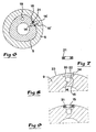
- a recess 20 is provided, said recess being adapted to receive a sealing ring 21.
- This recess may be manufactured by spark discharge and is designed with a bottom 22 having the same curved shape as the envelope surface, designated by 23, of the male part 9.
- the sealing ring 21 in this case is of uniform thickness and has a square or rectangular cross-section. In other words, the ring at arbitrary locations along its endless extension has square or rectangular cross-sectional shape.
- the sealing ring is manufactured from an elastic material like rubber. Especially, a rubber material is preferred having extra ordinary hardness.
- the initially planar sealing ring according to figure 7 receives a bent or curved shape when it is pressed into the recess 20 and the outward surface of the ring adapts to the generally curved shape of the surrounding envelope surface 23.
- FIG. 1 shows how the plate 13, apart from a number of holes 25 for fastening screws 26, includes a number of holes for cooling liquid, i.e. one hole 27 for low pressure cooling liquid and three holes 28 for high pressure liquid.
- a recess (not visible) is provided in the area of the three holes 28, said recess being common for all three holes 28 in order to distribute high pressure cooling liquid from the channel 14 to all of the holes 28.
- the hole 27 for low pressure cooling liquid is connected to the channel 19.
- all of the holes 27, 28 are completed by separate nozzle elements, not shown, that form the liquid to extremely thin jets (indicated by the lines 29) that, in response to the setting of the nozzle elements, can be directed towards desired portions of the cutting means.
- said cutting means of the tool said cutting means may be one or several, is to be cooled by high pressure liquid, said liquid is fed to the tool via the channel 14' in the head of the clamping unit. After having passed through the radial holes 15', 15 and the cooperating, effectively performing sealing ring 21, the liquid is transported, via the channel 14, up to the recess at the lower side of the plate 13, said recess being common for the high pressure holes 28. The liquid is then distributed to the different holes 28 and their nozzles. When the liquid passes the nozzles it is ejected in thin jets towards desired points of the cutting means in question.
- the low pressure liquid system forms a reserve system that continues to cool the cutting means in case the supply of high pressure liquid for some reason unintentionally is interrupted. In this way it is guaranteed that the cutting means is not overheated in case the high pressure liquid supply would cease in an uncontrolled way.
- the presence of both a high pressure liquid system as well as a low pressure liquid system also offers the benefit that the less energy consuming and thus cheaper low pressure liquid cooling can be used in case the workpiece is easy to machine and requires moderate cooling.
- cooling liquid of very high pressure e.g. in the area 500 - 1000 bar
- the invention is not solely limited to the embodiment described and shown in the drawings. Thus the invention is also applicable in connection with tools where cooling only by high pressure liquid is desirable.
- the male part of the tool may be designed as a uniform body without any cavity for low pressure liquid.
- a sealing ring having uniform thickness and a recess having curved bottom are preferred in practice it is also feasible to design the recess with a planar bottom and the sealing ring with an outer surface that joins the envelope surface of the male part due to the fact that two diametrically opposite portions of the ring have larger height than two diametrically opposite ring portions that are displaced by 90°.
- the invention may also be modified in several other ways within the scope of the appending claims.
Abstract
Claims (3)
- Outil pour couper le métal, ledit outil comprenant un corps principal ayant une première partie (7), un ou plusieurs moyens de coupe (8) pouvant être montés de manière détachable sur ladite première partie (7), et une deuxième partie axialement opposée (9) de type mâle, ladite deuxième partie (9) étant applicable dans un appui (6) dans une unité de serrage (2), à travers laquelle un moyen de refroidissement pour lesdits moyens de coupe (8) peut passer, via un canal, vers au moins une buse, à travers laquelle le moyen de refroidissement peut être éjecté dans une direction vers lesdits moyens de coupe, ledit canal de moyen de refroidissement comprenant d'une part une première section (14, 15) située à l'intérieur du corps principal et d'autre part une deuxième section (14', 15') à l'intérieur de l'unité de serrage, ladite deuxième section (14', 15') communiquant avec ladite première section (14, 15) et comprenant un trou radial (15') qui émerge dans la surface interne de l'appui (6), ledit emplacement radial du trou (15') garantissant que le moyen de refroidissement peut passer dans la première section de canal (14, 15) sans appliquer aucune force axiale sensible sur l'outil, caractérisé en ce que le trou radial (15') dans l'unité de serrage (2) est arrangé pour coopérer avec un trou radial similaire (15) qui est inclus dans la première section de canal (14, 15) et émerge dans une surface de l'enveloppe (23) de la partie mâle (9), plus précisément dans une position périphérique qui correspond à la position périphérique pour le trou radial (15') de la deuxième section de canal, et en ce que dans la zone de l'orifice du trou radial (15) de la partie mâle (9) un retrait (20) pour un anneau d'étanchéité (21) est prévu, ledit anneau d'étanchéité (21) étant fabriqué à partir d'un matériau élastique et ayant essentiellement une section transversale carrée à des emplacements arbitraires le long de son extension sans fin, ledit anneau d'étanchéité (21) dans une condition sans contrainte ayant une épaisseur telle que sa partie de surface extérieure dépasse, d'une certaine distance uniforme, de la surface de l'enveloppe courbe (23) de la partie mâle (9), ledit appui (6) ainsi que ladite partie mâle (9) ayant une forme effilée axialement, et lesdits trous radiaux (15, 15'), par leur orientation transversale à l'axe longitudinal de l'outil et leur coopération avec ledit anneau d'étanchéité dans une zone frontière entre l'appui et la partie mâle, permettant le passage vers ladite buse d'un moyen de refroidissement ayant une pression extraordinairement élevée.
- Outil selon la revendication 1, ladite partie mâle (9) ayant la forme d'un manchon et ayant une cavité (11) émergeant à une extrémité libre de la partie mâle (9), un moyen de refroidissement basse pression pouvant passer à travers ladite cavité (11), caractérisé en ce que outre le canal mentionné en premier (14', 15', 14, 15) pour le moyen de refroidissement haute pression, un deuxième canal (19) est prévu, ledit deuxième canal (19) reliant ladite cavité (11) à au moins une deuxième buse, moyennant quoi le moyen de refroidissement haute pression et le moyen de refroidissement basse pression, si nécessaire, peuvent être éjectés simultanément vers lesdits moyens de coupe.
- Outil selon la revendication 1 ou 2, caractérisé en ce que le retrait (20) a une partie inférieure (22) ayant la même forme courbe que la surface de l'enveloppe (12) de la partie mâle (9) afin de pouvoir recevoir un anneau d'étanchéité (21) ayant une épaisseur uniforme et garantissant ainsi que ledit anneau d'étanchéité (21) sur toute son extension maintient sa projection à une distance uniforme au-delà de ladite surface de l'enveloppe.
Applications Claiming Priority (3)
| Application Number | Priority Date | Filing Date | Title |
|---|---|---|---|
| SE9701603A SE511565C2 (sv) | 1997-04-28 | 1997-04-28 | Verktyg för skärande bearbetning |
| SE9701603 | 1997-04-28 | ||
| PCT/SE1998/000765 WO1998048963A1 (fr) | 1997-04-28 | 1998-04-27 | Outil de coupe |
Publications (2)
| Publication Number | Publication Date |
|---|---|
| EP0979155A1 EP0979155A1 (fr) | 2000-02-16 |
| EP0979155B1 true EP0979155B1 (fr) | 2003-06-18 |
Family
ID=20406760
Family Applications (1)
| Application Number | Title | Priority Date | Filing Date |
|---|---|---|---|
| EP98920788A Expired - Lifetime EP0979155B1 (fr) | 1997-04-28 | 1998-04-27 | Outil de coupe |
Country Status (6)
| Country | Link |
|---|---|
| US (1) | US6312199B1 (fr) |
| EP (1) | EP0979155B1 (fr) |
| JP (1) | JP2001524033A (fr) |
| DE (1) | DE69815671T2 (fr) |
| SE (1) | SE511565C2 (fr) |
| WO (1) | WO1998048963A1 (fr) |
Cited By (2)
| Publication number | Priority date | Publication date | Assignee | Title |
|---|---|---|---|---|
| US9028181B2 (en) | 2010-12-23 | 2015-05-12 | Kennametal Inc. | Expansion chuck for loss-free transmission of a lubricating medium |
| CN105873702A (zh) * | 2013-12-30 | 2016-08-17 | 株式会社多仁精工 | 控制喷射筒夹 |
Families Citing this family (39)
| Publication number | Priority date | Publication date | Assignee | Title |
|---|---|---|---|---|
| SE514939C2 (sv) * | 1999-09-02 | 2001-05-21 | Sandvik Ab | Maskin för spånavskiljande bearbetning jämte skärverktyg för dylika maskiner |
| SE514938C2 (sv) * | 1999-09-02 | 2001-05-21 | Sandvik Ab | Skärverktyg |
| SE520088C2 (sv) * | 2000-04-06 | 2003-05-20 | Skf Sverige Ab | Metod för spånskärande bearbetning av ett arbetsstycke |
| NO319690B1 (no) * | 2001-01-23 | 2005-09-05 | Teeness Asa | Skjaerhode for verktoymaskiner |
| DE10128816B4 (de) * | 2001-06-15 | 2004-04-29 | MAPAL Fabrik für Präzisionswerkzeuge Dr. Kress KG | Werkzeug |
| US6652200B2 (en) * | 2001-11-01 | 2003-11-25 | Rolf H. Kraemer | Tool holder with coolant system |
| SE526174C2 (sv) * | 2002-07-01 | 2005-07-19 | Seco Tools Ab Publ | Koppling vid verktyg för spånavskiljande bearbetning där kopplingsdelarna endast kan monteras i ett läge |
| SE526255C2 (sv) * | 2003-03-14 | 2005-08-09 | Sandvik Intellectual Property | Verktyg och indexerbart skär för finsvarvning av rotationssymmetriska spår i arbetsstycken |
| JP4272021B2 (ja) * | 2003-09-12 | 2009-06-03 | ユニタック株式会社 | 深孔切削具 |
| US7325471B2 (en) * | 2004-09-07 | 2008-02-05 | Kennametal Inc. | Toolholder and cutting insert for a toolholder assembly |
| US7240593B2 (en) * | 2005-04-19 | 2007-07-10 | Roger Little | Miniature cutting insert holder |
| SE530581C2 (sv) * | 2006-11-28 | 2008-07-08 | Sandvik Intellectual Property | Verktyg och grundkropp för spånavskiljande innefattande två kanaler för en fluid |
| US7625157B2 (en) * | 2007-01-18 | 2009-12-01 | Kennametal Inc. | Milling cutter and milling insert with coolant delivery |
| US9101985B2 (en) | 2007-01-18 | 2015-08-11 | Kennametal Inc. | Cutting insert assembly and components thereof |
| US8439608B2 (en) | 2007-01-18 | 2013-05-14 | Kennametal Inc. | Shim for a cutting insert and cutting insert-shim assembly with internal coolant delivery |
| US8454274B2 (en) | 2007-01-18 | 2013-06-04 | Kennametal Inc. | Cutting inserts |
| US8727673B2 (en) | 2007-01-18 | 2014-05-20 | Kennametal Inc. | Cutting insert with internal coolant delivery and surface feature for enhanced coolant flow |
| US20080175679A1 (en) * | 2007-01-18 | 2008-07-24 | Paul Dehnhardt Prichard | Milling cutter and milling insert with core and coolant delivery |
| US7883299B2 (en) | 2007-01-18 | 2011-02-08 | Kennametal Inc. | Metal cutting system for effective coolant delivery |
| US7963729B2 (en) | 2007-01-18 | 2011-06-21 | Kennametal Inc. | Milling cutter and milling insert with coolant delivery |
| US8328471B2 (en) | 2007-01-18 | 2012-12-11 | Kennametal Inc. | Cutting insert with internal coolant delivery and cutting assembly using the same |
| DE102007033167A1 (de) * | 2007-07-17 | 2009-01-22 | Kennametal Inc. | Modulares Werkzeugsystem |
| US7955032B2 (en) | 2009-01-06 | 2011-06-07 | Kennametal Inc. | Cutting insert with coolant delivery and method of making the cutting insert |
| US8827599B2 (en) | 2010-09-02 | 2014-09-09 | Kennametal Inc. | Cutting insert assembly and components thereof |
| US8734062B2 (en) | 2010-09-02 | 2014-05-27 | Kennametal Inc. | Cutting insert assembly and components thereof |
| AU2011333341A1 (en) | 2010-11-24 | 2013-07-11 | No Screw Ltd. | Cutting tool with cooling mechanism and a cutting insert and tool holder therefor |
| US8388268B2 (en) * | 2011-03-07 | 2013-03-05 | Kennametal Inc. | Cutting assembly |
| DE102011016148A1 (de) * | 2011-03-28 | 2012-10-04 | Ernst Graf Gmbh | Werkzeug zur spanenden Bearbeitung eines Werkstücks mit seitlichem Kühlmittelaustritt |
| US8827598B2 (en) | 2011-11-22 | 2014-09-09 | Kennametal Inc. | Cutting assembly with enhanced coolant delivery |
| KR20140026172A (ko) * | 2012-08-24 | 2014-03-05 | 대구텍 유한회사 | 내경 가공용 선삭 공구 |
| US9586263B2 (en) | 2014-06-05 | 2017-03-07 | Kennametal Inc | Tool holder having improved internal coolant delivery |
| CN105619168B (zh) * | 2014-10-28 | 2017-12-22 | 富鼎电子科技(嘉善)有限公司 | 加工装置 |
| FR3034696B1 (fr) * | 2015-04-08 | 2017-09-01 | Snecma | Porte-outil pour outil de coupe a lubrifier |
| CN107848039B (zh) * | 2015-07-24 | 2019-11-12 | 京瓷株式会社 | 切削工具以及使用该切削工具的切削加工物的制造方法 |
| JP6634241B2 (ja) * | 2015-08-26 | 2020-01-22 | 京セラ株式会社 | 切削工具用ホルダおよび切削工具、並びにそれらを用いた切削加工物の製造方法 |
| US10252389B2 (en) | 2017-07-05 | 2019-04-09 | Kennametal Inc. | Quick-change clamping unit for toolholder and method of using same |
| CN111587158B (zh) * | 2018-04-30 | 2023-04-14 | 硬质金属工具厂保罗霍恩有限公司 | 用于加工工件的工具 |
| CN110899740B (zh) * | 2019-12-16 | 2021-04-02 | 株洲钻石切削刀具股份有限公司 | 一种内冷式内孔车削刀具 |
| CN112170947A (zh) * | 2020-09-28 | 2021-01-05 | 湖南南方机床有限公司 | 一种能径向伸缩的刀柄及刀杆 |
Family Cites Families (11)
| Publication number | Priority date | Publication date | Assignee | Title |
|---|---|---|---|---|
| CH621957A5 (fr) * | 1977-09-15 | 1981-03-13 | Dornag | |
| JPS5976749A (ja) * | 1982-10-23 | 1984-05-01 | Okuma Mach Works Ltd | 加工面の洗浄方法 |
| JPS6116249U (ja) * | 1984-06-29 | 1986-01-30 | 大昭和精機株式会社 | 給油装置付タツパ− |
| US4695208A (en) * | 1985-11-14 | 1987-09-22 | Yankoff Gerald K | Tool holder |
| US5148728A (en) * | 1988-09-12 | 1992-09-22 | The Curator Of The University Of Missouri | High pressure lubricooling machining of metals |
| DE3838318A1 (de) * | 1988-11-11 | 1990-05-17 | Krupp Widia Gmbh | Werkzeugsystem |
| US4955264A (en) * | 1989-05-30 | 1990-09-11 | Kennametal Inc. | Tool assembly with a hydraulic chip-breaking fluid system |
| US5388487A (en) * | 1990-10-17 | 1995-02-14 | Sandvik Ab | Hydraulic tool holder with coolant jets |
| MX9205453A (es) | 1992-09-25 | 1994-05-31 | Kennametal Inc | Portaherramientas para romper astillas con tapa deorificio ajustable. |
| US5275516A (en) * | 1992-12-07 | 1994-01-04 | Liaw Jian Kuen | Structures of clamp head of numerically controlled cutting tool |
| US6076441A (en) * | 1998-08-18 | 2000-06-20 | Billington; Steven R. | Tool block and holder for metal working lathes |
-
1997
- 1997-04-28 SE SE9701603A patent/SE511565C2/sv not_active IP Right Cessation
-
1998
- 1998-04-27 JP JP54689598A patent/JP2001524033A/ja active Pending
- 1998-04-27 US US09/403,922 patent/US6312199B1/en not_active Expired - Lifetime
- 1998-04-27 DE DE69815671T patent/DE69815671T2/de not_active Expired - Lifetime
- 1998-04-27 WO PCT/SE1998/000765 patent/WO1998048963A1/fr active IP Right Grant
- 1998-04-27 EP EP98920788A patent/EP0979155B1/fr not_active Expired - Lifetime
Cited By (2)
| Publication number | Priority date | Publication date | Assignee | Title |
|---|---|---|---|---|
| US9028181B2 (en) | 2010-12-23 | 2015-05-12 | Kennametal Inc. | Expansion chuck for loss-free transmission of a lubricating medium |
| CN105873702A (zh) * | 2013-12-30 | 2016-08-17 | 株式会社多仁精工 | 控制喷射筒夹 |
Also Published As
| Publication number | Publication date |
|---|---|
| DE69815671D1 (de) | 2003-07-24 |
| WO1998048963A1 (fr) | 1998-11-05 |
| EP0979155A1 (fr) | 2000-02-16 |
| SE9701603D0 (sv) | 1997-04-28 |
| SE511565C2 (sv) | 1999-10-18 |
| US6312199B1 (en) | 2001-11-06 |
| DE69815671T2 (de) | 2004-04-22 |
| JP2001524033A (ja) | 2001-11-27 |
| SE9701603L (sv) | 1998-10-29 |
Similar Documents
| Publication | Publication Date | Title |
|---|---|---|
| EP0979155B1 (fr) | Outil de coupe | |
| EP0426808B1 (fr) | Ensemble outil a systeme de fluide hydraulique brise-copeaux | |
| EP1509352B1 (fr) | Outil de coupe rotatif | |
| JP3153315B2 (ja) | 互換性のあるカッタヘッドを持つリーマ | |
| US9238273B2 (en) | Milling tool | |
| EP1080811B1 (fr) | Outil de coupe | |
| EP2097197B1 (fr) | Outil destiné à l'usinage par élimination de copeaux et son corps de base | |
| US6109841A (en) | Drilling tool with replaceable bit | |
| JP6550759B2 (ja) | バイト | |
| CA2614650C (fr) | Ensemble porte-outil | |
| EP2416911B1 (fr) | Ensemble outil de coupe et porte-outil s'y rapportant | |
| KR100340397B1 (ko) | 칩제거용내부공동을갖는드릴본체 | |
| EP2001633B1 (fr) | Tete coupante et adaptateur | |
| EP1007255B1 (fr) | Raccordement pour outils | |
| KR20090094252A (ko) | 칩 제거 기계가공을 위한 공구 및 이 공구의 기본체 | |
| US4579488A (en) | Boring bar assembly | |
| JPH0747246B2 (ja) | リ−マ− | |
| JPH0710444B2 (ja) | スプリングコレット | |
| CN113727797A (zh) | T形刀具以及t形刀具的制作方法 | |
| EP1317981B1 (fr) | Porte-outil | |
| CA2196865C (fr) | Trepan a auto-chaufreinage | |
| JPH08276310A (ja) | 正面フライス | |
| GB2212078A (en) | Cutting tool with cutting fluid channel | |
| WO2023275727A1 (fr) | Outil de fraisage d'objets métalliques ou de matériaux durs et procédé de production associé | |
| CZ277929B6 (en) | Boring head, particularly for boring holes of greater diameters |
Legal Events
| Date | Code | Title | Description |
|---|---|---|---|
| PUAI | Public reference made under article 153(3) epc to a published international application that has entered the european phase |
Free format text: ORIGINAL CODE: 0009012 |
|
| 17P | Request for examination filed |
Effective date: 19991007 |
|
| AK | Designated contracting states |
Kind code of ref document: A1 Designated state(s): DE FR GB |
|
| GRAH | Despatch of communication of intention to grant a patent |
Free format text: ORIGINAL CODE: EPIDOS IGRA |
|
| GRAH | Despatch of communication of intention to grant a patent |
Free format text: ORIGINAL CODE: EPIDOS IGRA |
|
| GRAA | (expected) grant |
Free format text: ORIGINAL CODE: 0009210 |
|
| AK | Designated contracting states |
Designated state(s): DE FR GB |
|
| REG | Reference to a national code |
Ref country code: GB Ref legal event code: FG4D |
|
| REF | Corresponds to: |
Ref document number: 69815671 Country of ref document: DE Date of ref document: 20030724 Kind code of ref document: P |
|
| ET | Fr: translation filed | ||
| PLBE | No opposition filed within time limit |
Free format text: ORIGINAL CODE: 0009261 |
|
| STAA | Information on the status of an ep patent application or granted ep patent |
Free format text: STATUS: NO OPPOSITION FILED WITHIN TIME LIMIT |
|
| 26N | No opposition filed |
Effective date: 20040319 |
|
| REG | Reference to a national code |
Ref country code: GB Ref legal event code: 732E |
|
| REG | Reference to a national code |
Ref country code: GB Ref legal event code: 732E |
|
| REG | Reference to a national code |
Ref country code: FR Ref legal event code: TP |
|
| REG | Reference to a national code |
Ref country code: FR Ref legal event code: TP |
|
| REG | Reference to a national code |
Ref country code: FR Ref legal event code: PLFP Year of fee payment: 19 |
|
| REG | Reference to a national code |
Ref country code: FR Ref legal event code: PLFP Year of fee payment: 20 |
|
| PGFP | Annual fee paid to national office [announced via postgrant information from national office to epo] |
Ref country code: FR Payment date: 20170313 Year of fee payment: 20 |
|
| PGFP | Annual fee paid to national office [announced via postgrant information from national office to epo] |
Ref country code: GB Payment date: 20170426 Year of fee payment: 20 Ref country code: DE Payment date: 20170420 Year of fee payment: 20 |
|
| REG | Reference to a national code |
Ref country code: DE Ref legal event code: R071 Ref document number: 69815671 Country of ref document: DE |
|
| REG | Reference to a national code |
Ref country code: GB Ref legal event code: PE20 Expiry date: 20180426 |
|
| PG25 | Lapsed in a contracting state [announced via postgrant information from national office to epo] |
Ref country code: GB Free format text: LAPSE BECAUSE OF EXPIRATION OF PROTECTION Effective date: 20180426 |