EP0979155B1 - Cutting tool - Google Patents
Cutting tool Download PDFInfo
- Publication number
- EP0979155B1 EP0979155B1 EP98920788A EP98920788A EP0979155B1 EP 0979155 B1 EP0979155 B1 EP 0979155B1 EP 98920788 A EP98920788 A EP 98920788A EP 98920788 A EP98920788 A EP 98920788A EP 0979155 B1 EP0979155 B1 EP 0979155B1
- Authority
- EP
- European Patent Office
- Prior art keywords
- cooling medium
- tool
- male part
- channel
- section
- Prior art date
- Legal status (The legal status is an assumption and is not a legal conclusion. Google has not performed a legal analysis and makes no representation as to the accuracy of the status listed.)
- Expired - Lifetime
Links
Images


Classifications
-
- B—PERFORMING OPERATIONS; TRANSPORTING
- B23—MACHINE TOOLS; METAL-WORKING NOT OTHERWISE PROVIDED FOR
- B23Q—DETAILS, COMPONENTS, OR ACCESSORIES FOR MACHINE TOOLS, e.g. ARRANGEMENTS FOR COPYING OR CONTROLLING; MACHINE TOOLS IN GENERAL CHARACTERISED BY THE CONSTRUCTION OF PARTICULAR DETAILS OR COMPONENTS; COMBINATIONS OR ASSOCIATIONS OF METAL-WORKING MACHINES, NOT DIRECTED TO A PARTICULAR RESULT
- B23Q11/00—Accessories fitted to machine tools for keeping tools or parts of the machine in good working condition or for cooling work; Safety devices specially combined with or arranged in, or specially adapted for use in connection with, machine tools
- B23Q11/10—Arrangements for cooling or lubricating tools or work
- B23Q11/1084—Arrangements for cooling or lubricating tools or work specially adapted for being fitted to different kinds of machines
-
- B—PERFORMING OPERATIONS; TRANSPORTING
- B23—MACHINE TOOLS; METAL-WORKING NOT OTHERWISE PROVIDED FOR
- B23B—TURNING; BORING
- B23B27/00—Tools for turning or boring machines; Tools of a similar kind in general; Accessories therefor
- B23B27/10—Cutting tools with special provision for cooling
-
- B—PERFORMING OPERATIONS; TRANSPORTING
- B23—MACHINE TOOLS; METAL-WORKING NOT OTHERWISE PROVIDED FOR
- B23Q—DETAILS, COMPONENTS, OR ACCESSORIES FOR MACHINE TOOLS, e.g. ARRANGEMENTS FOR COPYING OR CONTROLLING; MACHINE TOOLS IN GENERAL CHARACTERISED BY THE CONSTRUCTION OF PARTICULAR DETAILS OR COMPONENTS; COMBINATIONS OR ASSOCIATIONS OF METAL-WORKING MACHINES, NOT DIRECTED TO A PARTICULAR RESULT
- B23Q11/00—Accessories fitted to machine tools for keeping tools or parts of the machine in good working condition or for cooling work; Safety devices specially combined with or arranged in, or specially adapted for use in connection with, machine tools
- B23Q11/10—Arrangements for cooling or lubricating tools or work
-
- B—PERFORMING OPERATIONS; TRANSPORTING
- B23—MACHINE TOOLS; METAL-WORKING NOT OTHERWISE PROVIDED FOR
- B23B—TURNING; BORING
- B23B2250/00—Compensating adverse effects during turning, boring or drilling
- B23B2250/12—Cooling and lubrication
-
- Y—GENERAL TAGGING OF NEW TECHNOLOGICAL DEVELOPMENTS; GENERAL TAGGING OF CROSS-SECTIONAL TECHNOLOGIES SPANNING OVER SEVERAL SECTIONS OF THE IPC; TECHNICAL SUBJECTS COVERED BY FORMER USPC CROSS-REFERENCE ART COLLECTIONS [XRACs] AND DIGESTS
- Y10—TECHNICAL SUBJECTS COVERED BY FORMER USPC
- Y10T—TECHNICAL SUBJECTS COVERED BY FORMER US CLASSIFICATION
- Y10T407/00—Cutters, for shaping
- Y10T407/11—Cutters, for shaping including chip breaker, guide or deflector detachable from tool and tool holder
- Y10T407/112—Adjustable relative to cutting edge
- Y10T407/114—Adjustable relative to cutting edge including adjusting means
-
- Y—GENERAL TAGGING OF NEW TECHNOLOGICAL DEVELOPMENTS; GENERAL TAGGING OF CROSS-SECTIONAL TECHNOLOGIES SPANNING OVER SEVERAL SECTIONS OF THE IPC; TECHNICAL SUBJECTS COVERED BY FORMER USPC CROSS-REFERENCE ART COLLECTIONS [XRACs] AND DIGESTS
- Y10—TECHNICAL SUBJECTS COVERED BY FORMER USPC
- Y10T—TECHNICAL SUBJECTS COVERED BY FORMER US CLASSIFICATION
- Y10T407/00—Cutters, for shaping
- Y10T407/11—Cutters, for shaping including chip breaker, guide or deflector detachable from tool and tool holder
- Y10T407/118—Chip breaker
-
- Y—GENERAL TAGGING OF NEW TECHNOLOGICAL DEVELOPMENTS; GENERAL TAGGING OF CROSS-SECTIONAL TECHNOLOGIES SPANNING OVER SEVERAL SECTIONS OF THE IPC; TECHNICAL SUBJECTS COVERED BY FORMER USPC CROSS-REFERENCE ART COLLECTIONS [XRACs] AND DIGESTS
- Y10—TECHNICAL SUBJECTS COVERED BY FORMER USPC
- Y10T—TECHNICAL SUBJECTS COVERED BY FORMER US CLASSIFICATION
- Y10T407/00—Cutters, for shaping
- Y10T407/14—Cutters, for shaping with means to apply fluid to cutting tool
-
- Y—GENERAL TAGGING OF NEW TECHNOLOGICAL DEVELOPMENTS; GENERAL TAGGING OF CROSS-SECTIONAL TECHNOLOGIES SPANNING OVER SEVERAL SECTIONS OF THE IPC; TECHNICAL SUBJECTS COVERED BY FORMER USPC CROSS-REFERENCE ART COLLECTIONS [XRACs] AND DIGESTS
- Y10—TECHNICAL SUBJECTS COVERED BY FORMER USPC
- Y10T—TECHNICAL SUBJECTS COVERED BY FORMER US CLASSIFICATION
- Y10T407/00—Cutters, for shaping
- Y10T407/20—Profiled circular tool
Definitions
- This invention relates to a tool for metal cutting, according to the preamble of claim 1, said tool comprising a main body having a first part, one or several cutting means being detachably mountable on said first part, and an axially opposite second part of male type, said second part being applicable in a seat in a clamping unit, through which a cooling medium for said cutting means may be fed, via a channel, to at least one nozzle, through which the cooling medium is allowed to be ejected in direction towards said cutting means.
- Tools of the type defined above are often used in machining centres, e.g. multi-purpose lathes for turning/milling.(See, for example, WO 90/14913 A). Depending on their function such tools may be equipped with widely different cutting means, i.e. inserts, milling cutters, drills, parting tools, etc. In connection with most tools the two axially opposite parts of the main body of the tool are spaced from each other via a radially projecting, flange ring that constitutes an integral part of the tool body, said first part carrying one or several cutting means may have a widely varied shape depending on the field of use.
- the second male type part is intended to be fastened in a mating seat in a clamping unit of the machine in question, said part being in the shape of a sleeve having an internal cavity that emerges at the free end of the male part, cooling medium, normally liquid, may be fed to the tool through said cavity.
- Said sleeve shaped male part has generally conical or tapering shape in order to be distinctly wedged up in a seat in the clamping unit, said seat having a corresponding shape, and that the clamping is effected by means of a mechanism incorporated in the clamping unit, said mechanism being able to on one hand internally gripping the male part and on the other hand pulling said male part into the seat to a firmly wedged position.
- Cooling of the cutting means of previously known tools is effected by a cooling liquid or other medium being fed to the cavity in the male part, said liquid or medium then being fed to a nozzle, via a smaller channel, and then ejected in a direction towards the cutting means.
- the cooling liquid is fed from a feeding device located centrally in the clamping unit in axial direction into the cavity of the male part.
- the pressure of the cooling liquid that is fed into the cavity is limited due to the fact that the liquid applies an axial force upon the tool, said axial force striving to detach the tool from the clamping unit. In practice the allowed liquid pressure is at most within the interval 50 - 70 bar. If a tool should be detached due to excessive pressures the machined workpiece may be damaged and destroyed; this being especially disastrous in connection with expensive workpieces.
- the present invention aims at overcoming the shortages mentioned above in connection with previously known tools and to create an improved tool.
- a basic object of the invention is thus to create a tool through which cooling liquid or cooling medium may be fed at extra ordinary pressure up to the nozzles in question.
- the invention aims at creating a tool by the aid of which high pressure cooling liquid and low pressure cooling liquid, if needed, may be ejected alternately towards the cutting means. It is also an object to create a tool that is able to receive high pressure cooling liquid without giving rise to liquid leakage problems.
- the reference numeral 1 designates a tool according to the invention while the reference numeral 2 designates a clamping unit for receiving and fixing the tool 1.
- This clamping unit 2 may in its turn be attached to a supporting member designated by the reference numeral 3, said supporting member 3 being incorporated in a machining centre.
- the clamping unit includes a tubular element 4 and a head 5 that includes a seat 6.
- coupling of the tool with the clamping unit is effected via a coupling of the type CAPTO(, said seat 6 having polygonal shape in cross-section and tapering shape in axial direction.
- the tool 1 comprises a first part 7 that may be equipped with a cutting means 8 in the shape of a cutting insert in the disclosed example.
- a second part 9, at the opposite side of the tool, is of male type to make it possible to insert said part 9 into the seat 6. More precisely, the male part 9, as well as the seat 6, has polygonal shape in cross-section and tapers towards its free end. In this connection it should be pointed out that the envelope surface of the male part 9, as well as the inner surface of the seat 6, has curved shape.
- the male part is separated from the first insert holding part 7 via an annular flange portion 10 that constitutes an integral part of the tool body manufactured in one single piece.
- the male part 9 in this case is in the shape of a sleeve.
- a cavity 11 is shaped within the male part.
- This cavity opens on one hand at the free end of the male part and terminates on the other hand at a suitable location within the tool main body. In the given example the cavity terminates in the area of the flange portion 10.
- the first part 7 is not disclosed (said first part continuing beyond the section surface 7'). In practice, the part 7 does only occupy a semi-circular sector area while the other semi-circular sector has a surface 12 for receiving a nozzle plate 13 (see figures 2 and 3).
- FIG 5 it is depicted how a first channel 14 extends between on one hand an essentially radial hole 15 that emerges in the envelope surface of the male part 9 and on the other hand an orifice opening 16 in the surface 12.
- a second channel extends between an internal orifice opening 17 in the cavity 11 and an orifice opening 18 in the surface 12. This channel can be seen in figure 6 and is designated by the reference numeral 19.
- the channel 14 emerges in the envelope surface of the male part 9, more precisely via the essentially radial hole 15.
- the clamping unit 2 in its head 5 includes a corresponding radial hole 15' (see figure 6) and an axial channel 14' through which cooling liquid is fed, said head 5 having an essentially annular cross-section.
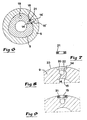
- a recess 20 is provided, said recess being adapted to receive a sealing ring 21.
- This recess may be manufactured by spark discharge and is designed with a bottom 22 having the same curved shape as the envelope surface, designated by 23, of the male part 9.
- the sealing ring 21 in this case is of uniform thickness and has a square or rectangular cross-section. In other words, the ring at arbitrary locations along its endless extension has square or rectangular cross-sectional shape.
- the sealing ring is manufactured from an elastic material like rubber. Especially, a rubber material is preferred having extra ordinary hardness.
- the initially planar sealing ring according to figure 7 receives a bent or curved shape when it is pressed into the recess 20 and the outward surface of the ring adapts to the generally curved shape of the surrounding envelope surface 23.
- FIG. 1 shows how the plate 13, apart from a number of holes 25 for fastening screws 26, includes a number of holes for cooling liquid, i.e. one hole 27 for low pressure cooling liquid and three holes 28 for high pressure liquid.
- a recess (not visible) is provided in the area of the three holes 28, said recess being common for all three holes 28 in order to distribute high pressure cooling liquid from the channel 14 to all of the holes 28.
- the hole 27 for low pressure cooling liquid is connected to the channel 19.
- all of the holes 27, 28 are completed by separate nozzle elements, not shown, that form the liquid to extremely thin jets (indicated by the lines 29) that, in response to the setting of the nozzle elements, can be directed towards desired portions of the cutting means.
- said cutting means of the tool said cutting means may be one or several, is to be cooled by high pressure liquid, said liquid is fed to the tool via the channel 14' in the head of the clamping unit. After having passed through the radial holes 15', 15 and the cooperating, effectively performing sealing ring 21, the liquid is transported, via the channel 14, up to the recess at the lower side of the plate 13, said recess being common for the high pressure holes 28. The liquid is then distributed to the different holes 28 and their nozzles. When the liquid passes the nozzles it is ejected in thin jets towards desired points of the cutting means in question.
- the low pressure liquid system forms a reserve system that continues to cool the cutting means in case the supply of high pressure liquid for some reason unintentionally is interrupted. In this way it is guaranteed that the cutting means is not overheated in case the high pressure liquid supply would cease in an uncontrolled way.
- the presence of both a high pressure liquid system as well as a low pressure liquid system also offers the benefit that the less energy consuming and thus cheaper low pressure liquid cooling can be used in case the workpiece is easy to machine and requires moderate cooling.
- cooling liquid of very high pressure e.g. in the area 500 - 1000 bar
- the invention is not solely limited to the embodiment described and shown in the drawings. Thus the invention is also applicable in connection with tools where cooling only by high pressure liquid is desirable.
- the male part of the tool may be designed as a uniform body without any cavity for low pressure liquid.
- a sealing ring having uniform thickness and a recess having curved bottom are preferred in practice it is also feasible to design the recess with a planar bottom and the sealing ring with an outer surface that joins the envelope surface of the male part due to the fact that two diametrically opposite portions of the ring have larger height than two diametrically opposite ring portions that are displaced by 90°.
- the invention may also be modified in several other ways within the scope of the appending claims.
Abstract
Description
- This invention relates to a tool for metal cutting, according to the preamble of claim 1, said tool comprising a main body having a first part, one or several cutting means being detachably mountable on said first part, and an axially opposite second part of male type, said second part being applicable in a seat in a clamping unit, through which a cooling medium for said cutting means may be fed, via a channel, to at least one nozzle, through which the cooling medium is allowed to be ejected in direction towards said cutting means.
- Tools of the type defined above are often used in machining centres, e.g. multi-purpose lathes for turning/milling.(See, for example, WO 90/14913 A). Depending on their function such tools may be equipped with widely different cutting means, i.e. inserts, milling cutters, drills, parting tools, etc. In connection with most tools the two axially opposite parts of the main body of the tool are spaced from each other via a radially projecting, flange ring that constitutes an integral part of the tool body, said first part carrying one or several cutting means may have a widely varied shape depending on the field of use. The second male type part is intended to be fastened in a mating seat in a clamping unit of the machine in question, said part being in the shape of a sleeve having an internal cavity that emerges at the free end of the male part, cooling medium, normally liquid, may be fed to the tool through said cavity. Said sleeve shaped male part has generally conical or tapering shape in order to be distinctly wedged up in a seat in the clamping unit, said seat having a corresponding shape, and that the clamping is effected by means of a mechanism incorporated in the clamping unit, said mechanism being able to on one hand internally gripping the male part and on the other hand pulling said male part into the seat to a firmly wedged position. Although tools having genuine conical male parts (i.e. male parts having circular cross-section) exist in practice male parts of the type CAPTO( are preferred, said parts having a polygonal, essentially triangular cross-section that guarantees the tool to automatically have a correct position as regards the angle of rotation relative to the clamping unit (said unit including a seat having corresponding polygonal shape).
- Cooling of the cutting means of previously known tools is effected by a cooling liquid or other medium being fed to the cavity in the male part, said liquid or medium then being fed to a nozzle, via a smaller channel, and then ejected in a direction towards the cutting means. The cooling liquid is fed from a feeding device located centrally in the clamping unit in axial direction into the cavity of the male part. The pressure of the cooling liquid that is fed into the cavity is limited due to the fact that the liquid applies an axial force upon the tool, said axial force striving to detach the tool from the clamping unit. In practice the allowed liquid pressure is at most within the interval 50 - 70 bar. If a tool should be detached due to excessive pressures the machined workpiece may be damaged and destroyed; this being especially disastrous in connection with expensive workpieces.
- Within modern engineering industry the materials of the workpieces in question are more frequently hard to machine, e.g. blanks for manufacturing of engine blocks. For this reason a definite need exists to increase the cooling liquid pressure on one hand to effectively cool the cutting means and on the other hand to properly remove chips from the workpiece. However, it has not been possible to increase the liquid pressure in connection with previously known tools due to the fact that the cooling liquid then would apply too high axial forces upon the tool.
- The present invention aims at overcoming the shortages mentioned above in connection with previously known tools and to create an improved tool. A basic object of the invention is thus to create a tool through which cooling liquid or cooling medium may be fed at extra ordinary pressure up to the nozzles in question. In a certain aspect the invention aims at creating a tool by the aid of which high pressure cooling liquid and low pressure cooling liquid, if needed, may be ejected alternately towards the cutting means. It is also an object to create a tool that is able to receive high pressure cooling liquid without giving rise to liquid leakage problems.
- According to the invention at least the primary object of the invention is realised through the features that are defined in claim 1. Preferred embodiments of the invention are further defined in the dependent claims.
- In the drawings:
- Figure 1
- shows a perspective exploded view of a tool and a clamping unit for the fixation of the tool,
- Figure 2
- shows a schematic perspective view that illustrates parts of the tool, especially a nozzle plate,
- Figure 3
- shows an end view that illustrates said nozzle plate,
- Figure 4
- shows a partial longitudinal section through the tool,
- Figure 5
- shows an analogous, although perspective, longitudinal section at an angle relative to the section according to figure 4,
- Figure 6
- shows a cross-section through the male part of the tool and a surrounding portion of the clamping unit,
- Figure 7
- shows a cross-section through a sealing ring,
- Figure 8
- shows a partial, enlarged section that illustrates a recess cut into the envelope surface of the male part, said recess being intended to receive the sealing ring according to figure 7, and
- Figure 9
- shows a corresponding section where the sealing ring is applied in the recess.
- In figure 1 the reference numeral 1 designates a tool according to the invention while the reference numeral 2 designates a clamping unit for receiving and fixing the tool 1. This clamping unit 2 may in its turn be attached to a supporting member designated by the reference numeral 3, said supporting member 3 being incorporated in a machining centre. In the given example the clamping unit includes a
tubular element 4 and ahead 5 that includes a seat 6. In the example coupling of the tool with the clamping unit is effected via a coupling of the type CAPTO(, said seat 6 having polygonal shape in cross-section and tapering shape in axial direction. - The tool 1 comprises a
first part 7 that may be equipped with a cutting means 8 in the shape of a cutting insert in the disclosed example. Asecond part 9, at the opposite side of the tool, is of male type to make it possible to insert saidpart 9 into the seat 6. More precisely, themale part 9, as well as the seat 6, has polygonal shape in cross-section and tapers towards its free end. In this connection it should be pointed out that the envelope surface of themale part 9, as well as the inner surface of the seat 6, has curved shape. The male part is separated from the firstinsert holding part 7 via anannular flange portion 10 that constitutes an integral part of the tool body manufactured in one single piece. - Reference is now being made also to figures 2-9, the figures 4 and 5 illustrating that the
male part 9 in this case is in the shape of a sleeve. This means that, in a previously known way, acavity 11 is shaped within the male part. This cavity opens on one hand at the free end of the male part and terminates on the other hand at a suitable location within the tool main body. In the given example the cavity terminates in the area of theflange portion 10. In figures 5 and 6 thefirst part 7 is not disclosed (said first part continuing beyond the section surface 7'). In practice, thepart 7 does only occupy a semi-circular sector area while the other semi-circular sector has asurface 12 for receiving a nozzle plate 13 (see figures 2 and 3). In figure 5 it is depicted how afirst channel 14 extends between on one hand an essentiallyradial hole 15 that emerges in the envelope surface of themale part 9 and on the other hand an orifice opening 16 in thesurface 12. A second channel extends between an internal orifice opening 17 in thecavity 11 and an orifice opening 18 in thesurface 12. This channel can be seen in figure 6 and is designated by thereference numeral 19. - It is essential for the present invention that the
channel 14 emerges in the envelope surface of themale part 9, more precisely via the essentiallyradial hole 15. This means that cooling liquid of high pressure may be fed into the tool in radial direction from the clamping unit 2 without applying any substantial axial forces upon the tool. In this connection it should be pointed out that the clamping unit 2 in itshead 5 includes a corresponding radial hole 15' (see figure 6) and an axial channel 14' through which cooling liquid is fed, saidhead 5 having an essentially annular cross-section. - In connection with the realisation of the invention the provision of a reliable sealing between respective high pressure liquid channels in the clamping unit and the tool has been a problem hard to master. This problem has been solved in the way shown in figures 7-9.
- In connection with the
radial hole 15 in themale part 9 of the tool arecess 20 is provided, said recess being adapted to receive a sealingring 21. This recess may be manufactured by spark discharge and is designed with a bottom 22 having the same curved shape as the envelope surface, designated by 23, of themale part 9. The sealingring 21 in this case is of uniform thickness and has a square or rectangular cross-section. In other words, the ring at arbitrary locations along its endless extension has square or rectangular cross-sectional shape. In practice the sealing ring is manufactured from an elastic material like rubber. Especially, a rubber material is preferred having extra ordinary hardness. While the hardness of rubber in conventional O-rings reaches 50 - 60 Shore it is suitable to use rubber having a hardness of 90 Shore in the ring. In its stress-flee condition shown in figure 7 the sealing ring has a thickness that is somewhat larger than the depth of therecess 20. This means that the outer surface portion of the sealing ring, as long as the tool is removed from the clamping unit, will project, by a certain uniform distance, beyond thecurved envelope surface 23 of the male part. When the male part is inserted into the seat of the clamping unit the elastic material of the ring will thus be compressed. In this connection it should be pointed out that the initially planar sealing ring according to figure 7 receives a bent or curved shape when it is pressed into therecess 20 and the outward surface of the ring adapts to the generally curved shape of the surroundingenvelope surface 23. - When the male part of the tool is inserted into the seat of the clamping unit the elastic material of the
ring 21 will be compressed, whereby said ring, due to its rectangular cross-section, will be firmly fastened in the annular space that is defined between the bottom 22, theannular surface 24 and the curved inner surface that surrounds the radial hole 15' in theclamping unit 5. When cooling liquid at high pressure passes from the radial hole 15' into theradial hole 15 of the male part the sealingring 21 is only subjected to shear forces that constantly strive to further compress the ring in a direction transverse to the common centre axis of the holes. This means that the surface pressure of the sealing ring against surrounding annular seat surfaces is increased by increasing cooling liquid pressure; this guarantees an extremely effective sealing of the transition between the two radial holes. - Reference is now being made to figures 2 and 3 showing how the
plate 13, apart from a number ofholes 25 for fastening screws 26, includes a number of holes for cooling liquid, i.e. onehole 27 for low pressure cooling liquid and threeholes 28 for high pressure liquid. At the lower side of the plate 13 a recess (not visible) is provided in the area of the threeholes 28, said recess being common for all threeholes 28 in order to distribute high pressure cooling liquid from thechannel 14 to all of theholes 28. Thehole 27 for low pressure cooling liquid is connected to thechannel 19. In practice all of theholes - The described tool works in the following way. In case the cutting means of the tool, said cutting means may be one or several, is to be cooled by high pressure liquid, said liquid is fed to the tool via the channel 14' in the head of the clamping unit. After having passed through the radial holes 15', 15 and the cooperating, effectively performing sealing
ring 21, the liquid is transported, via thechannel 14, up to the recess at the lower side of theplate 13, said recess being common for the high pressure holes 28. The liquid is then distributed to thedifferent holes 28 and their nozzles. When the liquid passes the nozzles it is ejected in thin jets towards desired points of the cutting means in question. During cooling of the cutting means by the high pressure liquid cooling may simultaneously be effected by the low pressure liquid that after insertion into thecavity 11 passes through thechannel 19 to thehole 27 and the adherent nozzle. By this possibility to simultaneously eject both high pressure cooling liquid as well as low pressure cooling liquid the benefit is achieved that the low pressure liquid system forms a reserve system that continues to cool the cutting means in case the supply of high pressure liquid for some reason unintentionally is interrupted. In this way it is guaranteed that the cutting means is not overheated in case the high pressure liquid supply would cease in an uncontrolled way. The presence of both a high pressure liquid system as well as a low pressure liquid system also offers the benefit that the less energy consuming and thus cheaper low pressure liquid cooling can be used in case the workpiece is easy to machine and requires moderate cooling. The basic advantage of the invention is however that cooling liquid of very high pressure, e.g. in the area 500 - 1000 bar, may be used in connection with workpieces that are hard to machine in order to on one hand to effectively cool the cutting means in question and on the other hand to remove chips that adhere firmly to the machined portions of the workpiece. - The invention is not solely limited to the embodiment described and shown in the drawings. Thus the invention is also applicable in connection with tools where cooling only by high pressure liquid is desirable. In such cases the male part of the tool may be designed as a uniform body without any cavity for low pressure liquid. Although a sealing ring having uniform thickness and a recess having curved bottom are preferred in practice it is also feasible to design the recess with a planar bottom and the sealing ring with an outer surface that joins the envelope surface of the male part due to the fact that two diametrically opposite portions of the ring have larger height than two diametrically opposite ring portions that are displaced by 90°. The invention may also be modified in several other ways within the scope of the appending claims.
Claims (3)
- Tool for metal cutting, said tool comprising a main body having a first part (7), one or several cutting means (8) being detachably mountable on said first part (7), and an axially opposite second part (9) of male type, said second part (9) being applicable in a seat (6) in a clamping unit (2), through which a cooling medium for said cutting means (8) may be fed, via a channel, to at least one nozzle, through which the cooling medium is allowed to be ejected in direction towards said cutting means, said cooling medium channel including on one hand a first section (14, 15) located within the main body and on the other hand a second section (14', 15') within the clamping unit, said second section (14', 15') communicating with said first section (14, 15) and comprising a radial hole (15') that emerges in the internal surface of the seat (6), said radial location of the hole (15') guaranteeing that cooling medium is allowed to be fed into the first channel section (14, 15) without applying any substantial axial forces upon the tool,
characterized in that the radial hole (15') in the clamping unit (2) is arranged to cooperate with a likewise radial hole (15) that is included in the first channel section (14, 15) and emerges in an envelope surface (23) of the male part (9), more precisely in a peripheral position that corresponds to the peripheral position for the radial hole (15') of the second channel section, and that in the area of the orifice of the radial hole (15) of the male part (9) a recess (20) for a sealing ring (21) is provided, said sealing ring (21) being manufactured from elastic material and having essentially square cross-section at arbitrary locations along its endless extension, said sealing ring (21) in a stress-free condition having such a thickness that its outer surface portion by a uniform distance projects beyond a curved envelope surface (23) of the male part (9), said seat (6) as well as said male part (9) having axially tapering shape, and said radial holes (15, 15'), by their orientation transverse to the longitudinal axis of the tool and their cooperation with said sealing ring in a border zone between the seat and the male part, enabling feeding to said nozzle of cooling medium having extra ordinarily high pressure. - Tool according to claim 1, said male part (9) being in the shape of a sleeve and having a cavity (11) emerging in a free end of the male part (9), a low pressure cooling medium may be fed into said cavity (11), characterizedin that apart from the first mentioned channel (14', 15', 15, 14) for high pressure cooling medium a second channel (19) is provided, said second channel (19) connecting said cavity (11) with at least a second nozzle, whereby high pressure cooling medium and low pressure cooling medium, if needed, may be ejected simultaneously towards said cutting means.
- Tool according to claim 1 or 2, characterized in that the recess (20) has a bottom (22) having the same curved shape as the envelope surface (23) of the male part (9) in order to be able to receive a sealing ring (21) having uniform thickness and thus guaranteeing that said sealing ring (21) along its entire extension maintains its projection a uniform distance beyond said envelope surface.
Applications Claiming Priority (3)
| Application Number | Priority Date | Filing Date | Title |
|---|---|---|---|
| SE9701603 | 1997-04-28 | ||
| SE9701603A SE511565C2 (en) | 1997-04-28 | 1997-04-28 | Tools for cutting machining |
| PCT/SE1998/000765 WO1998048963A1 (en) | 1997-04-28 | 1998-04-27 | Cutting tool |
Publications (2)
| Publication Number | Publication Date |
|---|---|
| EP0979155A1 EP0979155A1 (en) | 2000-02-16 |
| EP0979155B1 true EP0979155B1 (en) | 2003-06-18 |
Family
ID=20406760
Family Applications (1)
| Application Number | Title | Priority Date | Filing Date |
|---|---|---|---|
| EP98920788A Expired - Lifetime EP0979155B1 (en) | 1997-04-28 | 1998-04-27 | Cutting tool |
Country Status (6)
| Country | Link |
|---|---|
| US (1) | US6312199B1 (en) |
| EP (1) | EP0979155B1 (en) |
| JP (1) | JP2001524033A (en) |
| DE (1) | DE69815671T2 (en) |
| SE (1) | SE511565C2 (en) |
| WO (1) | WO1998048963A1 (en) |
Cited By (2)
| Publication number | Priority date | Publication date | Assignee | Title |
|---|---|---|---|---|
| US9028181B2 (en) | 2010-12-23 | 2015-05-12 | Kennametal Inc. | Expansion chuck for loss-free transmission of a lubricating medium |
| CN105873702A (en) * | 2013-12-30 | 2016-08-17 | 株式会社多仁精工 | Jet-controlling collet |
Families Citing this family (39)
| Publication number | Priority date | Publication date | Assignee | Title |
|---|---|---|---|---|
| SE514938C2 (en) * | 1999-09-02 | 2001-05-21 | Sandvik Ab | Cutting Tools |
| SE514939C2 (en) | 1999-09-02 | 2001-05-21 | Sandvik Ab | Machine for chip separating machining and cutting tools for such machines |
| SE520088C2 (en) * | 2000-04-06 | 2003-05-20 | Skf Sverige Ab | Method for chip cutting machining of a workpiece |
| NO319690B1 (en) * | 2001-01-23 | 2005-09-05 | Teeness Asa | Cutter head for machine tools |
| DE10128816B4 (en) * | 2001-06-15 | 2004-04-29 | MAPAL Fabrik für Präzisionswerkzeuge Dr. Kress KG | Tool |
| US6652200B2 (en) * | 2001-11-01 | 2003-11-25 | Rolf H. Kraemer | Tool holder with coolant system |
| SE526174C2 (en) * | 2002-07-01 | 2005-07-19 | Seco Tools Ab Publ | Coupling for chip separation tools where the coupling parts can only be mounted in one position |
| SE526255C2 (en) * | 2003-03-14 | 2005-08-09 | Sandvik Intellectual Property | Tools and indexable inserts for fine turning of rotationally symmetrical grooves in workpieces |
| JP4272021B2 (en) * | 2003-09-12 | 2009-06-03 | ユニタック株式会社 | Deep hole cutting tool |
| US7325471B2 (en) * | 2004-09-07 | 2008-02-05 | Kennametal Inc. | Toolholder and cutting insert for a toolholder assembly |
| US7240593B2 (en) * | 2005-04-19 | 2007-07-10 | Roger Little | Miniature cutting insert holder |
| SE530581C2 (en) * | 2006-11-28 | 2008-07-08 | Sandvik Intellectual Property | Chip separation tool and basic body comprising two channels for a fluid |
| US7883299B2 (en) | 2007-01-18 | 2011-02-08 | Kennametal Inc. | Metal cutting system for effective coolant delivery |
| US7963729B2 (en) | 2007-01-18 | 2011-06-21 | Kennametal Inc. | Milling cutter and milling insert with coolant delivery |
| US8328471B2 (en) | 2007-01-18 | 2012-12-11 | Kennametal Inc. | Cutting insert with internal coolant delivery and cutting assembly using the same |
| US8454274B2 (en) | 2007-01-18 | 2013-06-04 | Kennametal Inc. | Cutting inserts |
| US8727673B2 (en) | 2007-01-18 | 2014-05-20 | Kennametal Inc. | Cutting insert with internal coolant delivery and surface feature for enhanced coolant flow |
| US9101985B2 (en) | 2007-01-18 | 2015-08-11 | Kennametal Inc. | Cutting insert assembly and components thereof |
| US8439608B2 (en) | 2007-01-18 | 2013-05-14 | Kennametal Inc. | Shim for a cutting insert and cutting insert-shim assembly with internal coolant delivery |
| US7625157B2 (en) * | 2007-01-18 | 2009-12-01 | Kennametal Inc. | Milling cutter and milling insert with coolant delivery |
| US20080175679A1 (en) * | 2007-01-18 | 2008-07-24 | Paul Dehnhardt Prichard | Milling cutter and milling insert with core and coolant delivery |
| DE102007033167A1 (en) * | 2007-07-17 | 2009-01-22 | Kennametal Inc. | Modular tool system |
| US7955032B2 (en) | 2009-01-06 | 2011-06-07 | Kennametal Inc. | Cutting insert with coolant delivery and method of making the cutting insert |
| US8734062B2 (en) | 2010-09-02 | 2014-05-27 | Kennametal Inc. | Cutting insert assembly and components thereof |
| US8827599B2 (en) | 2010-09-02 | 2014-09-09 | Kennametal Inc. | Cutting insert assembly and components thereof |
| CA2821691A1 (en) | 2010-11-24 | 2012-05-31 | No Screw Ltd. | Cutting tool with cooling mechanism and a cutting insert and tool holder therefor |
| US8388268B2 (en) * | 2011-03-07 | 2013-03-05 | Kennametal Inc. | Cutting assembly |
| DE102011016148A1 (en) * | 2011-03-28 | 2012-10-04 | Ernst Graf Gmbh | Tool for machining a workpiece with lateral coolant outlet |
| US8827598B2 (en) | 2011-11-22 | 2014-09-09 | Kennametal Inc. | Cutting assembly with enhanced coolant delivery |
| KR20140026172A (en) * | 2012-08-24 | 2014-03-05 | 대구텍 유한회사 | Turning tool for machining bore |
| US9586263B2 (en) | 2014-06-05 | 2017-03-07 | Kennametal Inc | Tool holder having improved internal coolant delivery |
| CN105619168B (en) * | 2014-10-28 | 2017-12-22 | 富鼎电子科技(嘉善)有限公司 | Processing unit (plant) |
| FR3034696B1 (en) * | 2015-04-08 | 2017-09-01 | Snecma | TOOL HOLDER FOR LUBRICATING CUTTING TOOL |
| WO2017018369A1 (en) * | 2015-07-24 | 2017-02-02 | 京セラ株式会社 | Cutting tool and method for manufacturing machined workpiece using same |
| JP6634241B2 (en) * | 2015-08-26 | 2020-01-22 | 京セラ株式会社 | Cutting tool holder and cutting tool, and method of manufacturing cut workpiece using the same |
| US10252389B2 (en) | 2017-07-05 | 2019-04-09 | Kennametal Inc. | Quick-change clamping unit for toolholder and method of using same |
| EP3624972B1 (en) * | 2018-04-30 | 2021-01-06 | Hartmetall-Werkzeugfabrik Paul Horn GmbH | Tool for machining a workpiece |
| CN110899740B (en) * | 2019-12-16 | 2021-04-02 | 株洲钻石切削刀具股份有限公司 | Inner-cooling type inner hole turning tool |
| CN112170947A (en) * | 2020-09-28 | 2021-01-05 | 湖南南方机床有限公司 | Knife handle capable of radially extending and retracting and knife bar |
Family Cites Families (11)
| Publication number | Priority date | Publication date | Assignee | Title |
|---|---|---|---|---|
| CH621957A5 (en) * | 1977-09-15 | 1981-03-13 | Dornag | |
| JPS5976749A (en) * | 1982-10-23 | 1984-05-01 | Okuma Mach Works Ltd | Washing of working surface |
| JPS6116249U (en) * | 1984-06-29 | 1986-01-30 | 大昭和精機株式会社 | Tapper with oil supply device |
| US4695208A (en) * | 1985-11-14 | 1987-09-22 | Yankoff Gerald K | Tool holder |
| US5148728A (en) | 1988-09-12 | 1992-09-22 | The Curator Of The University Of Missouri | High pressure lubricooling machining of metals |
| DE3838318A1 (en) * | 1988-11-11 | 1990-05-17 | Krupp Widia Gmbh | TOOLING SYSTEM |
| US4955264A (en) * | 1989-05-30 | 1990-09-11 | Kennametal Inc. | Tool assembly with a hydraulic chip-breaking fluid system |
| US5388487A (en) * | 1990-10-17 | 1995-02-14 | Sandvik Ab | Hydraulic tool holder with coolant jets |
| US5340242A (en) | 1992-09-25 | 1994-08-23 | Kennametal Inc. | Chip-breaking toolholder with adjustable orifice cap |
| US5275516A (en) * | 1992-12-07 | 1994-01-04 | Liaw Jian Kuen | Structures of clamp head of numerically controlled cutting tool |
| US6076441A (en) * | 1998-08-18 | 2000-06-20 | Billington; Steven R. | Tool block and holder for metal working lathes |
-
1997
- 1997-04-28 SE SE9701603A patent/SE511565C2/en not_active IP Right Cessation
-
1998
- 1998-04-27 US US09/403,922 patent/US6312199B1/en not_active Expired - Lifetime
- 1998-04-27 JP JP54689598A patent/JP2001524033A/en active Pending
- 1998-04-27 EP EP98920788A patent/EP0979155B1/en not_active Expired - Lifetime
- 1998-04-27 DE DE69815671T patent/DE69815671T2/en not_active Expired - Lifetime
- 1998-04-27 WO PCT/SE1998/000765 patent/WO1998048963A1/en active IP Right Grant
Cited By (2)
| Publication number | Priority date | Publication date | Assignee | Title |
|---|---|---|---|---|
| US9028181B2 (en) | 2010-12-23 | 2015-05-12 | Kennametal Inc. | Expansion chuck for loss-free transmission of a lubricating medium |
| CN105873702A (en) * | 2013-12-30 | 2016-08-17 | 株式会社多仁精工 | Jet-controlling collet |
Also Published As
| Publication number | Publication date |
|---|---|
| SE511565C2 (en) | 1999-10-18 |
| DE69815671T2 (en) | 2004-04-22 |
| JP2001524033A (en) | 2001-11-27 |
| EP0979155A1 (en) | 2000-02-16 |
| WO1998048963A1 (en) | 1998-11-05 |
| SE9701603D0 (en) | 1997-04-28 |
| SE9701603L (en) | 1998-10-29 |
| US6312199B1 (en) | 2001-11-06 |
| DE69815671D1 (en) | 2003-07-24 |
Similar Documents
| Publication | Publication Date | Title |
|---|---|---|
| EP0979155B1 (en) | Cutting tool | |
| EP0426808B1 (en) | Tool assembly with a hydraulic chip-breaking fluid system | |
| EP1509352B1 (en) | Rotary cutting tool | |
| JP3153315B2 (en) | Reamer with compatible cutter head | |
| US9238273B2 (en) | Milling tool | |
| EP1080811B1 (en) | Cutting tool | |
| EP2097197B1 (en) | A tool for chip removing machining and a basic body therefor | |
| US6109841A (en) | Drilling tool with replaceable bit | |
| JP6550759B2 (en) | Part-Time Job | |
| EP2416911B1 (en) | Cutting tool assembly and tool holder therefor | |
| KR100340397B1 (en) | Drilling Tool with Internal Cavities for Chip Removal | |
| EP2001633B1 (en) | Cutting head and adaptor | |
| EP1007255B1 (en) | Tool coupling | |
| KR20090094252A (en) | A tool for chip removing machining and a basic body therefor | |
| US4579488A (en) | Boring bar assembly | |
| JPH0747246B2 (en) | Reamer | |
| JPH0710444B2 (en) | Spring collet | |
| CN113727797A (en) | T-shaped cutter and manufacturing method thereof | |
| EP1317981B1 (en) | Tool Holder | |
| EP3539696B1 (en) | Turning tool for metal cutting comprising a coolant channel | |
| CA2196865C (en) | Self-chamfering drill bit | |
| JPH08276310A (en) | Face milling cutter | |
| GB2212078A (en) | Cutting tool with cutting fluid channel | |
| WO2023275727A1 (en) | Tool for milling metal artefacts or hard materials and method for the production thereof | |
| JPH05212650A (en) | Cutting machine |
Legal Events
| Date | Code | Title | Description |
|---|---|---|---|
| PUAI | Public reference made under article 153(3) epc to a published international application that has entered the european phase |
Free format text: ORIGINAL CODE: 0009012 |
|
| 17P | Request for examination filed |
Effective date: 19991007 |
|
| AK | Designated contracting states |
Kind code of ref document: A1 Designated state(s): DE FR GB |
|
| GRAH | Despatch of communication of intention to grant a patent |
Free format text: ORIGINAL CODE: EPIDOS IGRA |
|
| GRAH | Despatch of communication of intention to grant a patent |
Free format text: ORIGINAL CODE: EPIDOS IGRA |
|
| GRAA | (expected) grant |
Free format text: ORIGINAL CODE: 0009210 |
|
| AK | Designated contracting states |
Designated state(s): DE FR GB |
|
| REG | Reference to a national code |
Ref country code: GB Ref legal event code: FG4D |
|
| REF | Corresponds to: |
Ref document number: 69815671 Country of ref document: DE Date of ref document: 20030724 Kind code of ref document: P |
|
| ET | Fr: translation filed | ||
| PLBE | No opposition filed within time limit |
Free format text: ORIGINAL CODE: 0009261 |
|
| STAA | Information on the status of an ep patent application or granted ep patent |
Free format text: STATUS: NO OPPOSITION FILED WITHIN TIME LIMIT |
|
| 26N | No opposition filed |
Effective date: 20040319 |
|
| REG | Reference to a national code |
Ref country code: GB Ref legal event code: 732E |
|
| REG | Reference to a national code |
Ref country code: GB Ref legal event code: 732E |
|
| REG | Reference to a national code |
Ref country code: FR Ref legal event code: TP |
|
| REG | Reference to a national code |
Ref country code: FR Ref legal event code: TP |
|
| REG | Reference to a national code |
Ref country code: FR Ref legal event code: PLFP Year of fee payment: 19 |
|
| REG | Reference to a national code |
Ref country code: FR Ref legal event code: PLFP Year of fee payment: 20 |
|
| PGFP | Annual fee paid to national office [announced via postgrant information from national office to epo] |
Ref country code: FR Payment date: 20170313 Year of fee payment: 20 |
|
| PGFP | Annual fee paid to national office [announced via postgrant information from national office to epo] |
Ref country code: GB Payment date: 20170426 Year of fee payment: 20 Ref country code: DE Payment date: 20170420 Year of fee payment: 20 |
|
| REG | Reference to a national code |
Ref country code: DE Ref legal event code: R071 Ref document number: 69815671 Country of ref document: DE |
|
| REG | Reference to a national code |
Ref country code: GB Ref legal event code: PE20 Expiry date: 20180426 |
|
| PG25 | Lapsed in a contracting state [announced via postgrant information from national office to epo] |
Ref country code: GB Free format text: LAPSE BECAUSE OF EXPIRATION OF PROTECTION Effective date: 20180426 |