EP2001633B1 - Cutting head and adaptor - Google Patents
Cutting head and adaptor Download PDFInfo
- Publication number
- EP2001633B1 EP2001633B1 EP07736162A EP07736162A EP2001633B1 EP 2001633 B1 EP2001633 B1 EP 2001633B1 EP 07736162 A EP07736162 A EP 07736162A EP 07736162 A EP07736162 A EP 07736162A EP 2001633 B1 EP2001633 B1 EP 2001633B1
- Authority
- EP
- European Patent Office
- Prior art keywords
- adaptor
- cutting
- fluid
- tool holder
- rod
- Prior art date
- Legal status (The legal status is an assumption and is not a legal conclusion. Google has not performed a legal analysis and makes no representation as to the accuracy of the status listed.)
- Active
Links
- 238000005520 cutting process Methods 0.000 title claims abstract description 71
- 239000012530 fluid Substances 0.000 claims abstract description 41
- 238000004891 communication Methods 0.000 claims description 4
- 238000009826 distribution Methods 0.000 abstract description 3
- 238000001816 cooling Methods 0.000 description 3
- 238000000034 method Methods 0.000 description 3
- 238000003801 milling Methods 0.000 description 3
- 230000002093 peripheral effect Effects 0.000 description 3
- 230000004075 alteration Effects 0.000 description 2
- 239000012809 cooling fluid Substances 0.000 description 2
- 238000003754 machining Methods 0.000 description 2
- 238000012986 modification Methods 0.000 description 2
- 230000004048 modification Effects 0.000 description 2
- 238000013459 approach Methods 0.000 description 1
- 239000000112 cooling gas Substances 0.000 description 1
- 239000000110 cooling liquid Substances 0.000 description 1
- 238000005461 lubrication Methods 0.000 description 1
- 239000003595 mist Substances 0.000 description 1
- 239000007921 spray Substances 0.000 description 1
Images


Classifications
-
- B—PERFORMING OPERATIONS; TRANSPORTING
- B23—MACHINE TOOLS; METAL-WORKING NOT OTHERWISE PROVIDED FOR
- B23C—MILLING
- B23C5/00—Milling-cutters
- B23C5/28—Features relating to lubricating or cooling
-
- B—PERFORMING OPERATIONS; TRANSPORTING
- B23—MACHINE TOOLS; METAL-WORKING NOT OTHERWISE PROVIDED FOR
- B23C—MILLING
- B23C5/00—Milling-cutters
- B23C5/02—Milling-cutters characterised by the shape of the cutter
- B23C5/06—Face-milling cutters, i.e. having only or primarily a substantially flat cutting surface
-
- B—PERFORMING OPERATIONS; TRANSPORTING
- B23—MACHINE TOOLS; METAL-WORKING NOT OTHERWISE PROVIDED FOR
- B23C—MILLING
- B23C2210/00—Details of milling cutters
- B23C2210/02—Connections between the shanks and detachable cutting heads
-
- Y—GENERAL TAGGING OF NEW TECHNOLOGICAL DEVELOPMENTS; GENERAL TAGGING OF CROSS-SECTIONAL TECHNOLOGIES SPANNING OVER SEVERAL SECTIONS OF THE IPC; TECHNICAL SUBJECTS COVERED BY FORMER USPC CROSS-REFERENCE ART COLLECTIONS [XRACs] AND DIGESTS
- Y10—TECHNICAL SUBJECTS COVERED BY FORMER USPC
- Y10T—TECHNICAL SUBJECTS COVERED BY FORMER US CLASSIFICATION
- Y10T279/00—Chucks or sockets
- Y10T279/16—Longitudinal screw clamp
-
- Y—GENERAL TAGGING OF NEW TECHNOLOGICAL DEVELOPMENTS; GENERAL TAGGING OF CROSS-SECTIONAL TECHNOLOGIES SPANNING OVER SEVERAL SECTIONS OF THE IPC; TECHNICAL SUBJECTS COVERED BY FORMER USPC CROSS-REFERENCE ART COLLECTIONS [XRACs] AND DIGESTS
- Y10—TECHNICAL SUBJECTS COVERED BY FORMER USPC
- Y10T—TECHNICAL SUBJECTS COVERED BY FORMER US CLASSIFICATION
- Y10T279/00—Chucks or sockets
- Y10T279/17—Socket type
- Y10T279/17111—Fluid-conduit drill holding
-
- Y—GENERAL TAGGING OF NEW TECHNOLOGICAL DEVELOPMENTS; GENERAL TAGGING OF CROSS-SECTIONAL TECHNOLOGIES SPANNING OVER SEVERAL SECTIONS OF THE IPC; TECHNICAL SUBJECTS COVERED BY FORMER USPC CROSS-REFERENCE ART COLLECTIONS [XRACs] AND DIGESTS
- Y10—TECHNICAL SUBJECTS COVERED BY FORMER USPC
- Y10T—TECHNICAL SUBJECTS COVERED BY FORMER US CLASSIFICATION
- Y10T407/00—Cutters, for shaping
- Y10T407/14—Cutters, for shaping with means to apply fluid to cutting tool
-
- Y—GENERAL TAGGING OF NEW TECHNOLOGICAL DEVELOPMENTS; GENERAL TAGGING OF CROSS-SECTIONAL TECHNOLOGIES SPANNING OVER SEVERAL SECTIONS OF THE IPC; TECHNICAL SUBJECTS COVERED BY FORMER USPC CROSS-REFERENCE ART COLLECTIONS [XRACs] AND DIGESTS
- Y10—TECHNICAL SUBJECTS COVERED BY FORMER USPC
- Y10T—TECHNICAL SUBJECTS COVERED BY FORMER US CLASSIFICATION
- Y10T408/00—Cutting by use of rotating axially moving tool
- Y10T408/44—Cutting by use of rotating axially moving tool with means to apply transient, fluent medium to work or product
- Y10T408/45—Cutting by use of rotating axially moving tool with means to apply transient, fluent medium to work or product including Tool with duct
- Y10T408/455—Conducting channel extending to end of Tool
-
- Y—GENERAL TAGGING OF NEW TECHNOLOGICAL DEVELOPMENTS; GENERAL TAGGING OF CROSS-SECTIONAL TECHNOLOGIES SPANNING OVER SEVERAL SECTIONS OF THE IPC; TECHNICAL SUBJECTS COVERED BY FORMER USPC CROSS-REFERENCE ART COLLECTIONS [XRACs] AND DIGESTS
- Y10—TECHNICAL SUBJECTS COVERED BY FORMER USPC
- Y10T—TECHNICAL SUBJECTS COVERED BY FORMER US CLASSIFICATION
- Y10T408/00—Cutting by use of rotating axially moving tool
- Y10T408/44—Cutting by use of rotating axially moving tool with means to apply transient, fluent medium to work or product
- Y10T408/46—Cutting by use of rotating axially moving tool with means to apply transient, fluent medium to work or product including nozzle
-
- Y—GENERAL TAGGING OF NEW TECHNOLOGICAL DEVELOPMENTS; GENERAL TAGGING OF CROSS-SECTIONAL TECHNOLOGIES SPANNING OVER SEVERAL SECTIONS OF THE IPC; TECHNICAL SUBJECTS COVERED BY FORMER USPC CROSS-REFERENCE ART COLLECTIONS [XRACs] AND DIGESTS
- Y10—TECHNICAL SUBJECTS COVERED BY FORMER USPC
- Y10T—TECHNICAL SUBJECTS COVERED BY FORMER US CLASSIFICATION
- Y10T408/00—Cutting by use of rotating axially moving tool
- Y10T408/89—Tool or Tool with support
- Y10T408/909—Having peripherally spaced cutting edges
- Y10T408/9098—Having peripherally spaced cutting edges with means to retain Tool to support
- Y10T408/90993—Screw driven means
-
- Y—GENERAL TAGGING OF NEW TECHNOLOGICAL DEVELOPMENTS; GENERAL TAGGING OF CROSS-SECTIONAL TECHNOLOGIES SPANNING OVER SEVERAL SECTIONS OF THE IPC; TECHNICAL SUBJECTS COVERED BY FORMER USPC CROSS-REFERENCE ART COLLECTIONS [XRACs] AND DIGESTS
- Y10—TECHNICAL SUBJECTS COVERED BY FORMER USPC
- Y10T—TECHNICAL SUBJECTS COVERED BY FORMER US CLASSIFICATION
- Y10T409/00—Gear cutting, milling, or planing
- Y10T409/30—Milling
- Y10T409/303976—Milling with means to control temperature or lubricate
- Y10T409/304032—Cutter or work
-
- Y—GENERAL TAGGING OF NEW TECHNOLOGICAL DEVELOPMENTS; GENERAL TAGGING OF CROSS-SECTIONAL TECHNOLOGIES SPANNING OVER SEVERAL SECTIONS OF THE IPC; TECHNICAL SUBJECTS COVERED BY FORMER USPC CROSS-REFERENCE ART COLLECTIONS [XRACs] AND DIGESTS
- Y10—TECHNICAL SUBJECTS COVERED BY FORMER USPC
- Y10T—TECHNICAL SUBJECTS COVERED BY FORMER US CLASSIFICATION
- Y10T409/00—Gear cutting, milling, or planing
- Y10T409/30—Milling
- Y10T409/30952—Milling with cutter holder
Definitions
- the invention relates generally to cutting tools and, more particularly, to the provision of a cooling fluid to a cutting tool operation by means of an adaptor according to the preamble of claim 1.
- An example of such an adaptor is known from WO 01/58 632 A1 .
- cutting heads are not configured with a fluid passage or other way to direct fluid to a cutting area.
- the cutting heads are secured to a tool holder, or optionally, to a machine spindle directly using a screw.
- the screw prevents provision of fluid towards the cutting region of the cutting head from the machine spindle because the screw is not provided with a corresponding channel for fluid.
- Such cutting heads eliminate or restrict the ability to use fluid during a cutting operation for cooling or chip-removal purposes.
- WO 01/58632 Al relates to a milling tool with a cutter head having a plurality of tangentially spaced-apart cutting inserts placed in chip spaces formed in an edge portion of the cutter head.
- the cutter head is provided with a screw by means of which the tool may be fixed in the usual way in a tool holder.
- the screw passes through a main duct that extends longitudinally within the cutter head for conducting fluid.
- the screw is in the form of a hollow tubular screw which has a center cavity for allowing axial passage of the fluid, and also has a screw head having a male screw thread.
- the cavity in the interior of the tubular screw terminates as a hexagonal socket in which a key may be applied to tighten the screw.
- a distributor device for directing the fluid radially outwardly has an internal screw thread and is screw threaded on the male screw thread of the screw head. To access the hexagonal socket the distributor device has to be removed.
- Fig. 1 shows a perspective view of a cutting tool having a cutting head secured to a tool holder
- Fig. 2 shows a cross sectional view taken in the plane N-N of the cutting tool of Fig. 1 according to a first exemplar embodiment
- Fig. 3 shows a perspective view of an adaptor of the cutting tool of Fig. 2 ;
- Fig. 4 shows a cross sectional view of an alternate cutting tool taken in the plane N-N embodiment
- Fig. 5 shows an exploded view of the cutting tool of Fig. 4 ;
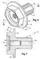
- Fig. 6 shows a perspective view of the adaptor shown in Fig. 4 ;
- Fig. 7 shows a cross sectional view of the adaptor taken along the plane VII-VII of Fig. 6 ;
- Fig. 8 shows a perspective view of a third exemplar embodiment of an adaptor
- Fig. 9 shows a perspective view of a fourth exemplar embodiment of an adaptor.
- Fig. 10 shows an exploded view of an embodiment of the adaptor of Fig. 6 assembled with a nozzle secured by a lock-nut.
- Figs. 1 and 4 show a face milling cutting tool 10 having a longitudinal tool axis A which defines a forward direction F and a rear direction R.
- Each part of the cutting tool 10 is described herein according to its respective orientation in the cutting tool 10 and in relation to the tool axis A. It should be noted that directional terms such as “forward”, “rear,” and the like are for illustrative purposes only and are not intended to limit the scope of the appended claims.
- the cutting tool 10 includes a tool holder 12, 14, a face milling cutting head 16 having a plurality of cutting inserts 18, an adaptor 20, 76, and a nozzle 22.
- the adaptor 20, 76 secures the cutting head 16 to a forward end of the tool holder 12, 14 and accommodates the nozzle 22 at a forward end thereof.
- the nozzle 22 may be any means, industrial or non-industrial, that is capable of transferring and distributing fluid forwardly or towards the cutting inserts 18 by separate fluid streams, spray, fog, and the like as are known in the art and need no further description herein.
- the adaptor 20, 76 provides a fluid path therethrough, thereby enabling fluid flowing from the tool holder 12, 14 to be distributed at a forward end of the cutting tool 10 via the nozzle 22.
- the fluid may be a cooling liquid that is supplied for the purpose of cooling the cutting inserts and/or the workpiece being machined.
- the fluid may consist of air with a mist of oil for providing both lubrication and cooling.
- cooling gases may form the fluid.
- the cooling fluid may provide the further benefit of removing chips formed by the cutting inserts 18 during the machining of the workpiece.
- Fig. 2 shows an example first tool holder 12 upon which the cutting head 16 may be secured.
- the first tool holder 12 is an HSK type tool holder which may be provided with an internal holder channel 24 that has a generally cylindrical holder wall 26 extending axially along the tool axis A.
- the tool holder 12 has a holder face 28 and a generally cylindrical shaft 30 having a forwardly facing shaft face 32.
- the holder face 28 faces forwardly, and the shaft 30 extends axially forwardly from the holder face 28 along the tool axis A to the shaft face 32.
- the holder wall 26 extends through the tool holder 12 and opens out to the shaft face 32.
- a holder thread 34 is formed on a forward portion of the holder wall 26.
- the cutting head 16 has a rearwardly facing support face 36 at a rear end thereof, a forwardly facing head face 38, and a peripheral side surface 40 extending therebetween.
- a recess 42 and a cavity 44 are formed in the cutting head 16 along the tool axis A.
- the recess 42 has a generally cylindrical recess wall 46 having a recess diameter D R and a stop wall 48 which is perpendicular to the recess wall 46.
- the recess wall 46 extends axially forwardly from the stop wall 48 and opens out to the head face 38.
- the cavity 44 has a generally cylindrical cavity wall 50 having a cavity diameter D C that extends axially, opens out to the support face 36, and communicates with the recess 42 via the stop wall 48.
- the recess diameter D R is larger than the cavity diameter D C .
- a rim 52 of the cutting head 16 is formed at the intersection of the head face 38 and the side surface 40.
- the assembly process of the cutting tool 10 wherein the cutting head 16 is assembled on the first tool holder 12 includes placing the cutting head 16 above the first tool holder 12 so that they axially align and the support face 36 of the cutting head 16 faces the holder face 28 of the first tool holder 12. From this position, the cutting head 16 is urged axially rearwardly until the support face 36 and the holder face 28 abut and the shaft 30 is located in the cavity 44.
- a first embodiment of the adaptor 20 has a rear threaded rod 56 and a forward cap 58.
- the cap 58 has a rearwardly facing cap face 60 (seen in Fig. 2 ).
- the threaded rod 56 extends axially rearwardly from the cap face 60 along the tool axis A.
- the cap 58 additionally has a rear generally cylindrical flange 62 having a flange diameter D F ( Fig. 2 ) and a forward hexagonal head 64.
- the flange 62 extends axially along the tool axis A to a forwardly facing flange face 66, and the head 64 extends forwardly from the flange face 66 along the tool axis A to a forward end of the adaptor 20.
- the adaptor 20 has an adaptor channel 68 having a generally cylindrical adaptor wall 70 that extends axially through the adaptor 20 along the tool axis A. A forward portion of the adaptor wall 70 forms an adaptor thread 72.
- the flange diameter D F is larger than the channel diameter D C and smaller than the recess diameter D R .
- the cutting tool 10 of this embodiment is assembled by screwing the threaded rod 56 of the adaptor 20 into the holder thread 34 of the first tool holder 12 until the cap face 60 of the adaptor 20 bears against the stop wall 48 of the cutting head 16, thereby securing the cutting head 16 to the first tool holder 12.
- the adaptor channel 68 is in fluid communication with the holder channel 24.
- the nozzle 22 may then be screwed into the adaptor thread 72 to distribute fluid flowing from the first tool holder 12 in a distribution direction D towards the cutting region 54 of the cutting head 16.
- Fig. 4 shows a second example of a tool holder 14 upon which the cutting head 16 may be secured.
- the second tool holder 14 is a BT type tool holder that, similarly to the first tool holder 12, has a holder face 28 and a cylindrical shaft 30 having a forwardly facing shaft face 32.
- the holder face 28 faces forwardly, and the shaft 30 extends axially forwardly from the holder face 28 along the tool axis A to the shaft face 32.
- the second tool holder 14 has a pair of front holder channels 74 that extend axially forwardly through the shaft 30 and open out through the shaft face 32.
- the assembly process of the cutting tool 10 with the second tool holder 14 is performed in a similar manner to the assembly process with the first tool holder 12.
- the cutting head 16 is placed above the second tool holder 14 so that they axially align and the support face 36 of the cutting head 16 faces the holder face 28 of the second tool holder 14. From this position, the cutting head 16 is urged axially rearwardly until the support face 36 and the holder face 28 abut and the shaft 30 is located in the cavity 44 of the cutting head 16.
- Figs. 6 and 7 show a second embodiment of the adaptor 76.
- the adaptor 76 has a rear threaded rod 78 and a forward cap 80.
- the cap 80 has a rearwardly facing cap face 82 (seen in Fig. 4 ).
- the threaded rod 78 extends axially rearwardly from the cap face 82 along the tool axis A to a rearwardly facing rod face 84 ( Fig. 4 ).
- the cap 80 additionally has a rear cylindrical flange 86 having a flange diameter D F ( Fig. 4 ) and a forward hexagonal head 88.
- the flange 86 extends axially along the tool axis A to a forwardly facing flange face 90, and the head 88 extends forwardly from the flange face 90 along the tool axis A to a forward end of the adaptor 76.
- the adaptor 76 has two side adaptor channels 92 and a main adaptor channel 94.
- the side adaptor channels 92 are symmetrically formed about the tool axis A on a peripheral surface of the threaded rod 78.
- Each side adaptor channel 92 extends axially rearwardly from a channel forward ending 96 (seen in Fig. 4 ) along the peripheral surface of the threaded rod 78 and opens out to the rod face 84.
- the main adaptor channel 94 has a cylindrical main adaptor wall 98 that extends axially through the adaptor 76 along the tool axis A .
- a forward portion of the main adaptor wall 98 forms a main adaptor thread 100.
- the threaded rod 78 of the adaptor 76 is screwed into the holder thread 34 of the second tool holder 14 until the cap face 82 of the adaptor 76 bears against the stop wall 48 of the cutting head 16, thereby securing the cutting head 16 to the second tool holder 14.
- a gap 102 is formed between the cap face 82 of the adaptor 76 and the shaft face 32 of the second tool holder 14. The gap 102 is in fluid communication with the front holder channels 74 and the side adaptor channels 92.
- fluid flowing from the second tool holder 14 towards the cutting region 54 of the cutting tool 10 will flow forwardly through the front holder channels 74, through the gap 102, rearwardly through the side adaptor channels 92, and forwardly again through the main adaptor channel 94 until reaching the nozzle 22.
- the nozzle 22 is threadingly engaged in the main adaptor thread 100.
- Figs. 8 and 9 show respectively a third 104 and a fourth 106 example embodiments of the adaptor.
- the third and the fourth embodiments 104, 106 of the adaptor are similar to the second embodiment 76 of the adaptor with the exception of the shape of the head 88.
- the head 88 is of a general X shape
- the head 88 is of a general cylindrical shape having three key ways 108 at a forward end thereof.
- Fig. 10 shows an embodiment of the adaptor 76 assembled with a nozzle 122 that is secured by a lock-nut 150.
- the nozzle 122 screws into the adaptor 76 and is locked by the lock-nut 150, which allows for controlling an overhang of the nozzle 122 from the adaptor 76. So configured, and thus a fluid flow distribution to a cutting region can be controlled, at least in part, through control of the overhang.
Abstract
Description
- The invention relates generally to cutting tools and, more particularly, to the provision of a cooling fluid to a cutting tool operation by means of an adaptor according to the preamble of claim 1. An example of such an adaptor is known from
WO 01/58 632 A1 - Machining work pieces through the use of rotating cutting tools, especially those rotating at high speeds, can cause a large build up of heat in the workpiece and cutting tool. To combat the heat build up, it is known to provide a fluid to the cutting tool and/or workpiece to cool those elements.
- Many cutting heads, however, are not configured with a fluid passage or other way to direct fluid to a cutting area. Generally, the cutting heads are secured to a tool holder, or optionally, to a machine spindle directly using a screw. In such a case, the screw prevents provision of fluid towards the cutting region of the cutting head from the machine spindle because the screw is not provided with a corresponding channel for fluid. Such cutting heads eliminate or restrict the ability to use fluid during a cutting operation for cooling or chip-removal purposes.
-
WO 01/58632 Al - This problem is solved by an adaptor having the features of claim 1.
-
Fig. 1 shows a perspective view of a cutting tool having a cutting head secured to a tool holder; -
Fig. 2 shows a cross sectional view taken in the plane N-N of the cutting tool ofFig. 1 according to a first exemplar embodiment; -
Fig. 3 shows a perspective view of an adaptor of the cutting tool ofFig. 2 ; -
Fig. 4 shows a cross sectional view of an alternate cutting tool taken in the plane N-N embodiment; -
Fig. 5 shows an exploded view of the cutting tool ofFig. 4 ; -
Fig. 6 shows a perspective view of the adaptor shown inFig. 4 ; -
Fig. 7 shows a cross sectional view of the adaptor taken along the plane VII-VII ofFig. 6 ; -
Fig. 8 shows a perspective view of a third exemplar embodiment of an adaptor; -
Fig. 9 shows a perspective view of a fourth exemplar embodiment of an adaptor; and -
Fig. 10 shows an exploded view of an embodiment of the adaptor ofFig. 6 assembled with a nozzle secured by a lock-nut. - It will be appreciated that for simplicity and clarity of illustration, elements shown in the figures have not necessarily been drawn to scale. For example, the dimensions of some of the elements may be exaggerated relative to other elements for clarity. Further, where considered appropriate, reference numerals may be repeated within the figures to indicate like elements. It is intended that the embodiments and figures disclosed herein are to be considered illustrative, rather than restrictive.
-
Figs. 1 and4 show a facemilling cutting tool 10 having a longitudinal tool axis A which defines a forward direction F and a rear direction R. Each part of thecutting tool 10 is described herein according to its respective orientation in thecutting tool 10 and in relation to the tool axis A. It should be noted that directional terms such as "forward", "rear," and the like are for illustrative purposes only and are not intended to limit the scope of the appended claims. - The
cutting tool 10 includes atool holder milling cutting head 16 having a plurality ofcutting inserts 18, anadaptor nozzle 22. Theadaptor cutting head 16 to a forward end of thetool holder nozzle 22 at a forward end thereof. - The
nozzle 22 may be any means, industrial or non-industrial, that is capable of transferring and distributing fluid forwardly or towards thecutting inserts 18 by separate fluid streams, spray, fog, and the like as are known in the art and need no further description herein. - The
adaptor tool holder cutting tool 10 via thenozzle 22. The fluid may be a cooling liquid that is supplied for the purpose of cooling the cutting inserts and/or the workpiece being machined. In other cases, the fluid may consist of air with a mist of oil for providing both lubrication and cooling. In other approaches, cooling gases may form the fluid. The cooling fluid may provide the further benefit of removing chips formed by thecutting inserts 18 during the machining of the workpiece. -
Fig. 2 shows an examplefirst tool holder 12 upon which thecutting head 16 may be secured. Thefirst tool holder 12 is an HSK type tool holder which may be provided with an internal holder channel 24 that has a generally cylindrical holder wall 26 extending axially along the tool axis A. Thetool holder 12 has aholder face 28 and a generallycylindrical shaft 30 having a forwardly facingshaft face 32. Theholder face 28 faces forwardly, and theshaft 30 extends axially forwardly from theholder face 28 along the tool axis A to theshaft face 32. The holder wall 26 extends through thetool holder 12 and opens out to theshaft face 32. Aholder thread 34 is formed on a forward portion of the holder wall 26. - The
cutting head 16 has a rearwardly facingsupport face 36 at a rear end thereof, a forwardly facinghead face 38, and aperipheral side surface 40 extending therebetween. Arecess 42 and acavity 44 are formed in thecutting head 16 along the tool axis A. Therecess 42 has a generallycylindrical recess wall 46 having a recess diameter DR and astop wall 48 which is perpendicular to therecess wall 46. Therecess wall 46 extends axially forwardly from thestop wall 48 and opens out to thehead face 38. Thecavity 44 has a generallycylindrical cavity wall 50 having a cavity diameter DC that extends axially, opens out to thesupport face 36, and communicates with therecess 42 via thestop wall 48. The recess diameter DR is larger than the cavity diameter DC . - A
rim 52 of thecutting head 16 is formed at the intersection of thehead face 38 and theside surface 40. Thecutting inserts 18, which are attached to thecutting head 16 along therim 52, define acutting region 54 of thecutting head 16. - The assembly process of the
cutting tool 10 wherein thecutting head 16 is assembled on thefirst tool holder 12 includes placing thecutting head 16 above thefirst tool holder 12 so that they axially align and thesupport face 36 of thecutting head 16 faces theholder face 28 of thefirst tool holder 12. From this position, thecutting head 16 is urged axially rearwardly until thesupport face 36 and theholder face 28 abut and theshaft 30 is located in thecavity 44. - With reference to
Fig. 3 , a first embodiment of theadaptor 20 has a rear threadedrod 56 and aforward cap 58. Thecap 58 has a rearwardly facing cap face 60 (seen inFig. 2 ). The threadedrod 56 extends axially rearwardly from thecap face 60 along the tool axis A. Thecap 58 additionally has a rear generallycylindrical flange 62 having a flange diameter DF (Fig. 2 ) and a forwardhexagonal head 64. Theflange 62 extends axially along the tool axis A to a forwardly facingflange face 66, and thehead 64 extends forwardly from theflange face 66 along the tool axis A to a forward end of theadaptor 20. Theadaptor 20 has anadaptor channel 68 having a generallycylindrical adaptor wall 70 that extends axially through theadaptor 20 along the tool axis A. A forward portion of theadaptor wall 70 forms anadaptor thread 72. The flange diameter DF is larger than the channel diameter DC and smaller than the recess diameter DR . - The cutting
tool 10 of this embodiment is assembled by screwing the threadedrod 56 of theadaptor 20 into theholder thread 34 of thefirst tool holder 12 until thecap face 60 of theadaptor 20 bears against thestop wall 48 of the cuttinghead 16, thereby securing the cuttinghead 16 to thefirst tool holder 12. In this position, theadaptor channel 68 is in fluid communication with the holder channel 24. Thenozzle 22 may then be screwed into theadaptor thread 72 to distribute fluid flowing from thefirst tool holder 12 in a distribution direction D towards the cuttingregion 54 of the cuttinghead 16. -
Fig. 4 shows a second example of atool holder 14 upon which the cuttinghead 16 may be secured. Thesecond tool holder 14 is a BT type tool holder that, similarly to thefirst tool holder 12, has aholder face 28 and acylindrical shaft 30 having a forwardly facingshaft face 32. Theholder face 28 faces forwardly, and theshaft 30 extends axially forwardly from theholder face 28 along the tool axis A to theshaft face 32. Thesecond tool holder 14 has a pair offront holder channels 74 that extend axially forwardly through theshaft 30 and open out through theshaft face 32. - The assembly process of the
cutting tool 10 with thesecond tool holder 14 is performed in a similar manner to the assembly process with thefirst tool holder 12. The cuttinghead 16 is placed above thesecond tool holder 14 so that they axially align and thesupport face 36 of the cuttinghead 16 faces theholder face 28 of thesecond tool holder 14. From this position, the cuttinghead 16 is urged axially rearwardly until thesupport face 36 and theholder face 28 abut and theshaft 30 is located in thecavity 44 of the cuttinghead 16. -
Figs. 6 and 7 show a second embodiment of theadaptor 76. Theadaptor 76 has a rear threadedrod 78 and aforward cap 80. Thecap 80 has a rearwardly facing cap face 82 (seen inFig. 4 ). The threadedrod 78 extends axially rearwardly from thecap face 82 along the tool axis A to a rearwardly facing rod face 84 (Fig. 4 ). Thecap 80 additionally has a rearcylindrical flange 86 having a flange diameter DF (Fig. 4 ) and a forwardhexagonal head 88. Theflange 86 extends axially along the tool axis A to a forwardly facingflange face 90, and thehead 88 extends forwardly from theflange face 90 along the tool axis A to a forward end of theadaptor 76. - The
adaptor 76 has twoside adaptor channels 92 and amain adaptor channel 94. Theside adaptor channels 92 are symmetrically formed about the tool axis A on a peripheral surface of the threadedrod 78. - Each
side adaptor channel 92 extends axially rearwardly from a channel forward ending 96 (seen inFig. 4 ) along the peripheral surface of the threadedrod 78 and opens out to therod face 84. Themain adaptor channel 94 has a cylindricalmain adaptor wall 98 that extends axially through theadaptor 76 along the tool axis A. A forward portion of themain adaptor wall 98 forms amain adaptor thread 100. - In the final assembled position of the
cutting tool 10 having thesecond tool holder 14, the threadedrod 78 of theadaptor 76 is screwed into theholder thread 34 of thesecond tool holder 14 until thecap face 82 of theadaptor 76 bears against thestop wall 48 of the cuttinghead 16, thereby securing the cuttinghead 16 to thesecond tool holder 14. In this final assembled position, agap 102 is formed between thecap face 82 of theadaptor 76 and theshaft face 32 of thesecond tool holder 14. Thegap 102 is in fluid communication with thefront holder channels 74 and theside adaptor channels 92. Therefore, fluid flowing from thesecond tool holder 14 towards the cuttingregion 54 of thecutting tool 10 will flow forwardly through thefront holder channels 74, through thegap 102, rearwardly through theside adaptor channels 92, and forwardly again through themain adaptor channel 94 until reaching thenozzle 22. Thenozzle 22 is threadingly engaged in themain adaptor thread 100. -
Figs. 8 and 9 show respectively a third 104 and a fourth 106 example embodiments of the adaptor. The third and thefourth embodiments second embodiment 76 of the adaptor with the exception of the shape of thehead 88. In the third embodiment of the adaptor 104 (Fig. 8 ), thehead 88 is of a general X shape, and in the fourth embodiment of the adaptor 106 (Fig. 9 ), thehead 88 is of a general cylindrical shape having threekey ways 108 at a forward end thereof. -
Fig. 10 shows an embodiment of theadaptor 76 assembled with anozzle 122 that is secured by a lock-nut 150. Thenozzle 122 screws into theadaptor 76 and is locked by the lock-nut 150, which allows for controlling an overhang of thenozzle 122 from theadaptor 76. So configured, and thus a fluid flow distribution to a cutting region can be controlled, at least in part, through control of the overhang. - Although the above embodiments have been described to a certain degree of particularity, it should be understood that various alterations, modifications, and combinations could be made without departing from the scope of the disclosure as hereinafter claimed. For example, the lock-nut configuration for the nozzle can be applied to nearly any embodiment. Similarly, any standard or non-standard tool holder provided with an internal channel for fluid may be used in connection with the teachings of this disclosure. Such modifications, alterations, and combinations of the disclosed elements are to be viewed as being within the ambit of the inventive concept.
Claims (9)
- An adaptor (20, 76, 104, 106) for a cutting tool (10) comprising:- a rod (56, 78) defining a fluid path;- a cap (58, 80) attached to an end of the rod (56, 78);- the rod (56, 78) and the cap (58, 80) defining a fluid path;- at least part of the cap (58, 80) being configured to support a nozzle (22) to deliver fluid from the fluid path to a cutting area;- wherein the cap (58, 80) has a radial dimension of sufficient dimension to engage a cutting head (16) and the rod (56, 78) has a length of sufficient dimension to engage a tool holder (12, 14), a combination thereof linking the cutting-head (16) to the tool holder (12, 14) in an axial direction,characterized in that:
the adaptor (20, 76, 104, 106) has an adaptor channel (68, 94) having a generally cylindrical adaptor wall (70) that extends axially through the adaptor (20, 76, 104, 106), a forward portion of the adaptor wall (70) forms an adaptor thread (72) in which the nozzle (22) is threadingly engaged. - The adaptor of claim 1 wherein the rod (56, 78) comprises a peripherally threaded rod (56, 78) wherein the peripherally threaded rod (56, 78) is configured to engage the tool holder (12, 14).
- The adaptor of claim 1 wherein the cap (58, 80) comprises a flange (62, 86) and a head (64, 88) through which the fluid path extends wherein the flange (62, 86) is configured to secure at least a portion of a cutting tool (10) to a cutting tool holder (12, 14) such that the fluid path of the rod (56, 78) is in fluid communication with a fluid source associated with the tool holder (12, 14).
- The adaptor of claim 3 wherein the fluid source is at least one holder channel (24) defined by the tool holder (12, 14).
- The adaptor of claim 4 wherein the holder channel (24) is generally co-axial with the fluid path.
- The adaptor of claim 3 wherein the head (64, 88) comprises at least one of a group comprising a hexagonal head, a general X shape, and a general cylindrical shape having a plurality of key ways (108).
- The adaptor of claim 1 wherein the rod (56, 78) defines an internal adaptor threading (72) defined by at least a portion of the fluid path proximal to the cap (58, 80) wherein the internal adaptor threading (72) is configured to engage the nozzle (22) for directing fluid from the fluid path to at least a portion of the cutting tool (10).
- The adaptor of claim 1 further comprising at least one side adaptor channel (92) defined by the rod (56, 78) wherein the at least one side adaptor channel (92) is in fluid communication with the fluid path and a fluid source associated with the tool holder (12, 14) when the adaptor (20, 76, 104, 106) secures a cutting tool (10) to the tool holder (12, 14).
- The adaptor of claim 1 further comprising a lock-nut (150) for securing a nozzle (22) to the cap (58, 80).
Priority Applications (1)
| Application Number | Priority Date | Filing Date | Title |
|---|---|---|---|
| PL07736162T PL2001633T3 (en) | 2006-04-02 | 2007-03-29 | Cutting head and adaptor |
Applications Claiming Priority (3)
| Application Number | Priority Date | Filing Date | Title |
|---|---|---|---|
| IL174721A IL174721A0 (en) | 2006-04-02 | 2006-04-02 | Cutting head and adaptor |
| IL181834A IL181834A (en) | 2006-04-02 | 2007-03-11 | Cutting head and adaptor |
| PCT/IL2007/000422 WO2007113820A1 (en) | 2006-04-02 | 2007-03-29 | Cutting head and adaptor |
Publications (2)
| Publication Number | Publication Date |
|---|---|
| EP2001633A1 EP2001633A1 (en) | 2008-12-17 |
| EP2001633B1 true EP2001633B1 (en) | 2010-01-13 |
Family
ID=38559174
Family Applications (1)
| Application Number | Title | Priority Date | Filing Date |
|---|---|---|---|
| EP07736162A Active EP2001633B1 (en) | 2006-04-02 | 2007-03-29 | Cutting head and adaptor |
Country Status (8)
| Country | Link |
|---|---|
| US (1) | US7537422B2 (en) |
| EP (1) | EP2001633B1 (en) |
| AT (1) | ATE454953T1 (en) |
| DE (1) | DE602007004312D1 (en) |
| ES (1) | ES2339071T3 (en) |
| IL (1) | IL181834A (en) |
| PL (1) | PL2001633T3 (en) |
| WO (1) | WO2007113820A1 (en) |
Families Citing this family (18)
| Publication number | Priority date | Publication date | Assignee | Title |
|---|---|---|---|---|
| TW200724269A (en) * | 2005-11-06 | 2007-07-01 | Iscar Ltd | Rotary cutting tool |
| US20090214305A1 (en) * | 2008-02-22 | 2009-08-27 | Waggle James M | Coolant nozzles for milling cutters |
| US8454284B2 (en) * | 2008-12-01 | 2013-06-04 | Kennametal Inc. | Milling cutter coupling system |
| IL197095A (en) | 2009-02-17 | 2013-02-28 | Iscar Ltd | Cutting tool having a retractable nozzle |
| DE102010018254B4 (en) * | 2010-04-23 | 2022-11-10 | Kennametal Inc. | coolant distributor |
| EP2394767A1 (en) * | 2010-06-10 | 2011-12-14 | Siemens Aktiengesellschaft | Through coolant adaptor for use on hollow spindle machine tools |
| US8596935B2 (en) | 2010-10-08 | 2013-12-03 | TDY Industries, LLC | Cutting tools and cutting inserts including internal cooling |
| US9180650B2 (en) | 2010-10-08 | 2015-11-10 | Kennametal Inc. | Cutting tool including an internal coolant system and fastener for a cutting tool including an internal coolant system |
| DE102010054392A1 (en) * | 2010-12-07 | 2012-06-14 | Hartmetall-Werkzeugfabrik Paul Horn Gmbh | Cutting tool for machining a tool |
| SE537368C2 (en) * | 2011-04-29 | 2015-04-14 | Sandvik Intellectual Property | Milling tools with a sealing cap |
| US8827610B2 (en) * | 2011-08-05 | 2014-09-09 | Kennametal Inc. | Hydraulic coupling system for coupling a shell mill to an adapter |
| CH705550A1 (en) * | 2011-09-16 | 2013-03-28 | Chirmat Sarl | Surgical tool for boring the diaphyseal canal of long bones. |
| CN102513563B (en) * | 2011-12-15 | 2013-10-30 | 株洲钻石切削刀具股份有限公司 | Cutting tool with internal cooling structure |
| DE102012216655A1 (en) * | 2012-09-18 | 2014-03-20 | Gühring KG | ROTATABLE CUTTING TOOL |
| CN104174919B (en) * | 2014-08-06 | 2018-02-09 | 沈阳理工大学 | The efficiently interior cooling swivel joint of Digit Control Machine Tool |
| JP6426405B2 (en) * | 2014-08-28 | 2018-11-21 | 京セラ株式会社 | Milling tool and method of manufacturing cut product using the same |
| MX369370B (en) * | 2015-04-08 | 2019-11-06 | Decatur Diamond Llc | Milling cutter with lubrication conduits. |
| US10610992B2 (en) | 2017-08-28 | 2020-04-07 | United Technologies Corporation | Automated interchangeable coolant distributor |
Citations (1)
| Publication number | Priority date | Publication date | Assignee | Title |
|---|---|---|---|---|
| WO2007085281A1 (en) * | 2006-01-28 | 2007-08-02 | Hartmetall-Werkzeugfabrik Paul Horn Gmbh | Cutting tool for machining |
Family Cites Families (18)
| Publication number | Priority date | Publication date | Assignee | Title |
|---|---|---|---|---|
| US2282596A (en) * | 1939-11-13 | 1942-05-12 | Edward T Wise | Replaceable bit for drill rods |
| US2867140A (en) * | 1955-12-15 | 1959-01-06 | Metal Cutting Tools Inc | Core drill |
| US4720216A (en) * | 1985-01-18 | 1988-01-19 | Smith Robert S | Cylindrical cutting tool |
| KR890015820A (en) * | 1988-04-28 | 1989-11-25 | 야스이 요시히로 | Processing liquid supply device |
| DE4033607A1 (en) * | 1990-10-23 | 1992-04-30 | Norbert Theis | TIGHTENING SCREW FOR ATTACHING A MILLING TOOL TO THE RECEIVING OF A MACHINE TOOL |
| AT397626B (en) * | 1992-11-20 | 1994-05-25 | Plansee Tizit Gmbh | CUTTING TOOL WITH INTEGRATED COOLANT FEED |
| GB2332161A (en) * | 1997-12-13 | 1999-06-16 | C And D Technologies Limited | Reuse of disposable cutter inserts |
| JP3390785B2 (en) * | 1999-11-12 | 2003-03-31 | 株式会社小松製作所 | Cutting tool |
| SE517817C2 (en) * | 2000-02-11 | 2002-07-16 | Sandvik Ab | Chip separation machining tool with groove-shaped coolant ducts in the end surface |
| DE10009721A1 (en) * | 2000-03-01 | 2001-09-06 | Komet Stahlhalter Werkzeuge | Machine reamer with axially protending head designs head as variable cutter plate with extension having three equi-spaced wedge faces forming truncated pyramid and matched by plate seat bevel faces. |
| DE60131981T2 (en) * | 2000-08-18 | 2008-12-18 | Iscar Ltd. | CUTTING TOOL ARRANGEMENT |
| IL150013A (en) * | 2002-06-04 | 2007-06-17 | Gil Hecht | Rotary cutting tool |
| JP4349824B2 (en) * | 2003-03-13 | 2009-10-21 | オーエスジー株式会社 | Fastening bolts for cutting tools |
| JP4175949B2 (en) * | 2003-05-13 | 2008-11-05 | 株式会社日研工作所 | Arbor for cutter |
| US7160062B2 (en) * | 2004-01-12 | 2007-01-09 | Toan Dat Tran | Milling cutter |
| DE102005031683A1 (en) * | 2005-07-05 | 2007-01-25 | Dihart Ag | machine tools |
| TW200724269A (en) * | 2005-11-06 | 2007-07-01 | Iscar Ltd | Rotary cutting tool |
| AU2007224651B8 (en) | 2006-03-14 | 2011-10-27 | Lidds Ab | Bioresorbable controlled-release composition |
-
2007
- 2007-03-11 IL IL181834A patent/IL181834A/en not_active IP Right Cessation
- 2007-03-29 DE DE602007004312T patent/DE602007004312D1/en active Active
- 2007-03-29 PL PL07736162T patent/PL2001633T3/en unknown
- 2007-03-29 WO PCT/IL2007/000422 patent/WO2007113820A1/en active Application Filing
- 2007-03-29 ES ES07736162T patent/ES2339071T3/en active Active
- 2007-03-29 AT AT07736162T patent/ATE454953T1/en active
- 2007-03-29 EP EP07736162A patent/EP2001633B1/en active Active
- 2007-04-02 US US11/695,306 patent/US7537422B2/en active Active
Patent Citations (1)
| Publication number | Priority date | Publication date | Assignee | Title |
|---|---|---|---|---|
| WO2007085281A1 (en) * | 2006-01-28 | 2007-08-02 | Hartmetall-Werkzeugfabrik Paul Horn Gmbh | Cutting tool for machining |
Also Published As
| Publication number | Publication date |
|---|---|
| EP2001633A1 (en) | 2008-12-17 |
| IL181834A (en) | 2011-04-28 |
| ES2339071T3 (en) | 2010-05-14 |
| US7537422B2 (en) | 2009-05-26 |
| WO2007113820A1 (en) | 2007-10-11 |
| US20070231097A1 (en) | 2007-10-04 |
| DE602007004312D1 (en) | 2010-03-04 |
| PL2001633T3 (en) | 2010-06-30 |
| ATE454953T1 (en) | 2010-01-15 |
| IL181834A0 (en) | 2007-07-04 |
Similar Documents
| Publication | Publication Date | Title |
|---|---|---|
| EP2001633B1 (en) | Cutting head and adaptor | |
| US9238273B2 (en) | Milling tool | |
| KR101749784B1 (en) | Rotary cutting tool having an adjustable cooling mechanism | |
| US8573098B2 (en) | Cutting tool including a locking screw and adapter with coolant delivery | |
| US8573901B2 (en) | Assembly for rotating a cutting insert during a turning operation and inserts used therein | |
| US5516242A (en) | Cutting tool and shank | |
| WO2016117461A1 (en) | Bit | |
| CN109789498B (en) | Disc cutter and kit comprising such a disc cutter | |
| US20120200050A1 (en) | Junction between two components of a rotating tool system | |
| US20100143051A1 (en) | Ball raceway milling device, tool having a ball raceway milling device, and method for the application of a ball raceway milling device | |
| US20180065196A1 (en) | Cutting tool having a coolant chamber with an integrally formed coolant deflection portion and tool body | |
| JPH0627046U (en) | Fluid supply device for tools | |
| US9770799B2 (en) | Rotating chuck with coolant groove arrangement | |
| WO2015056406A1 (en) | Cutting tool holder and cutting tool | |
| AU2007219146A1 (en) | Cutting tool | |
| US20090214305A1 (en) | Coolant nozzles for milling cutters | |
| US10814447B2 (en) | Cooling system and method for machine tools | |
| JP5310191B2 (en) | Insert detachable cutting tool | |
| JP4175949B2 (en) | Arbor for cutter | |
| US20120070237A1 (en) | Tool holder comprising a cooling means | |
| JP2014030888A (en) | Cutting tool | |
| US7357607B2 (en) | Tool holder | |
| JP2511368B2 (en) | Coolant supply method and device | |
| JP7419792B2 (en) | Slotting cutter with coolant hole and mounting member for the slotting cutter with coolant hole | |
| EP3495080B1 (en) | A tool body assembly, a tool assembly and a machine |
Legal Events
| Date | Code | Title | Description |
|---|---|---|---|
| PUAI | Public reference made under article 153(3) epc to a published international application that has entered the european phase |
Free format text: ORIGINAL CODE: 0009012 |
|
| 17P | Request for examination filed |
Effective date: 20081001 |
|
| AK | Designated contracting states |
Kind code of ref document: A1 Designated state(s): AT BE BG CH CY CZ DE DK EE ES FI FR GB GR HU IE IS IT LI LT LU LV MC MT NL PL PT RO SE SI SK TR |
|
| 17Q | First examination report despatched |
Effective date: 20090216 |
|
| RIN1 | Information on inventor provided before grant (corrected) |
Inventor name: BALLAS, ASSAF Inventor name: FELDMAN, DAVID Inventor name: SMILOVICI, CAROL |
|
| GRAP | Despatch of communication of intention to grant a patent |
Free format text: ORIGINAL CODE: EPIDOSNIGR1 |
|
| GRAS | Grant fee paid |
Free format text: ORIGINAL CODE: EPIDOSNIGR3 |
|
| GRAA | (expected) grant |
Free format text: ORIGINAL CODE: 0009210 |
|
| DAX | Request for extension of the european patent (deleted) | ||
| AK | Designated contracting states |
Kind code of ref document: B1 Designated state(s): AT BE BG CH CY CZ DE DK EE ES FI FR GB GR HU IE IS IT LI LT LU LV MC MT NL PL PT RO SE SI SK TR |
|
| REG | Reference to a national code |
Ref country code: GB Ref legal event code: FG4D |
|
| REG | Reference to a national code |
Ref country code: CH Ref legal event code: EP |
|
| REG | Reference to a national code |
Ref country code: IE Ref legal event code: FG4D |
|
| REG | Reference to a national code |
Ref country code: SE Ref legal event code: TRGR |
|
| REF | Corresponds to: |
Ref document number: 602007004312 Country of ref document: DE Date of ref document: 20100304 Kind code of ref document: P |
|
| REG | Reference to a national code |
Ref country code: NL Ref legal event code: VDEP Effective date: 20100113 |
|
| REG | Reference to a national code |
Ref country code: ES Ref legal event code: FG2A Ref document number: 2339071 Country of ref document: ES Kind code of ref document: T3 |
|
| LTIE | Lt: invalidation of european patent or patent extension |
Effective date: 20100113 |
|
| PG25 | Lapsed in a contracting state [announced via postgrant information from national office to epo] |
Ref country code: PT Free format text: LAPSE BECAUSE OF FAILURE TO SUBMIT A TRANSLATION OF THE DESCRIPTION OR TO PAY THE FEE WITHIN THE PRESCRIBED TIME-LIMIT Effective date: 20100513 Ref country code: NL Free format text: LAPSE BECAUSE OF FAILURE TO SUBMIT A TRANSLATION OF THE DESCRIPTION OR TO PAY THE FEE WITHIN THE PRESCRIBED TIME-LIMIT Effective date: 20100113 Ref country code: LT Free format text: LAPSE BECAUSE OF FAILURE TO SUBMIT A TRANSLATION OF THE DESCRIPTION OR TO PAY THE FEE WITHIN THE PRESCRIBED TIME-LIMIT Effective date: 20100113 Ref country code: IS Free format text: LAPSE BECAUSE OF FAILURE TO SUBMIT A TRANSLATION OF THE DESCRIPTION OR TO PAY THE FEE WITHIN THE PRESCRIBED TIME-LIMIT Effective date: 20100513 |
|
| PG25 | Lapsed in a contracting state [announced via postgrant information from national office to epo] |
Ref country code: FI Free format text: LAPSE BECAUSE OF FAILURE TO SUBMIT A TRANSLATION OF THE DESCRIPTION OR TO PAY THE FEE WITHIN THE PRESCRIBED TIME-LIMIT Effective date: 20100113 Ref country code: SI Free format text: LAPSE BECAUSE OF FAILURE TO SUBMIT A TRANSLATION OF THE DESCRIPTION OR TO PAY THE FEE WITHIN THE PRESCRIBED TIME-LIMIT Effective date: 20100113 Ref country code: LV Free format text: LAPSE BECAUSE OF FAILURE TO SUBMIT A TRANSLATION OF THE DESCRIPTION OR TO PAY THE FEE WITHIN THE PRESCRIBED TIME-LIMIT Effective date: 20100113 |
|
| PG25 | Lapsed in a contracting state [announced via postgrant information from national office to epo] |
Ref country code: BE Free format text: LAPSE BECAUSE OF FAILURE TO SUBMIT A TRANSLATION OF THE DESCRIPTION OR TO PAY THE FEE WITHIN THE PRESCRIBED TIME-LIMIT Effective date: 20100113 Ref country code: MC Free format text: LAPSE BECAUSE OF NON-PAYMENT OF DUE FEES Effective date: 20100331 Ref country code: RO Free format text: LAPSE BECAUSE OF FAILURE TO SUBMIT A TRANSLATION OF THE DESCRIPTION OR TO PAY THE FEE WITHIN THE PRESCRIBED TIME-LIMIT Effective date: 20100113 Ref country code: CY Free format text: LAPSE BECAUSE OF FAILURE TO SUBMIT A TRANSLATION OF THE DESCRIPTION OR TO PAY THE FEE WITHIN THE PRESCRIBED TIME-LIMIT Effective date: 20100113 Ref country code: EE Free format text: LAPSE BECAUSE OF FAILURE TO SUBMIT A TRANSLATION OF THE DESCRIPTION OR TO PAY THE FEE WITHIN THE PRESCRIBED TIME-LIMIT Effective date: 20100113 Ref country code: GR Free format text: LAPSE BECAUSE OF FAILURE TO SUBMIT A TRANSLATION OF THE DESCRIPTION OR TO PAY THE FEE WITHIN THE PRESCRIBED TIME-LIMIT Effective date: 20100414 |
|
| PLBE | No opposition filed within time limit |
Free format text: ORIGINAL CODE: 0009261 |
|
| STAA | Information on the status of an ep patent application or granted ep patent |
Free format text: STATUS: NO OPPOSITION FILED WITHIN TIME LIMIT |
|
| PG25 | Lapsed in a contracting state [announced via postgrant information from national office to epo] |
Ref country code: SK Free format text: LAPSE BECAUSE OF FAILURE TO SUBMIT A TRANSLATION OF THE DESCRIPTION OR TO PAY THE FEE WITHIN THE PRESCRIBED TIME-LIMIT Effective date: 20100113 Ref country code: BG Free format text: LAPSE BECAUSE OF FAILURE TO SUBMIT A TRANSLATION OF THE DESCRIPTION OR TO PAY THE FEE WITHIN THE PRESCRIBED TIME-LIMIT Effective date: 20100413 |
|
| 26N | No opposition filed |
Effective date: 20101014 |
|
| PG25 | Lapsed in a contracting state [announced via postgrant information from national office to epo] |
Ref country code: IE Free format text: LAPSE BECAUSE OF NON-PAYMENT OF DUE FEES Effective date: 20100329 Ref country code: DK Free format text: LAPSE BECAUSE OF FAILURE TO SUBMIT A TRANSLATION OF THE DESCRIPTION OR TO PAY THE FEE WITHIN THE PRESCRIBED TIME-LIMIT Effective date: 20100113 |
|
| PG25 | Lapsed in a contracting state [announced via postgrant information from national office to epo] |
Ref country code: MT Free format text: LAPSE BECAUSE OF FAILURE TO SUBMIT A TRANSLATION OF THE DESCRIPTION OR TO PAY THE FEE WITHIN THE PRESCRIBED TIME-LIMIT Effective date: 20100113 |
|
| PGRI | Patent reinstated in contracting state [announced from national office to epo] |
Ref country code: IT Effective date: 20110501 |
|
| PGRI | Patent reinstated in contracting state [announced from national office to epo] |
Ref country code: IT Effective date: 20110501 |
|
| REG | Reference to a national code |
Ref country code: CH Ref legal event code: PL |
|
| PG25 | Lapsed in a contracting state [announced via postgrant information from national office to epo] |
Ref country code: LI Free format text: LAPSE BECAUSE OF NON-PAYMENT OF DUE FEES Effective date: 20110331 Ref country code: CH Free format text: LAPSE BECAUSE OF NON-PAYMENT OF DUE FEES Effective date: 20110331 |
|
| PG25 | Lapsed in a contracting state [announced via postgrant information from national office to epo] |
Ref country code: HU Free format text: LAPSE BECAUSE OF FAILURE TO SUBMIT A TRANSLATION OF THE DESCRIPTION OR TO PAY THE FEE WITHIN THE PRESCRIBED TIME-LIMIT Effective date: 20100714 Ref country code: LU Free format text: LAPSE BECAUSE OF NON-PAYMENT OF DUE FEES Effective date: 20100329 |
|
| REG | Reference to a national code |
Ref country code: FR Ref legal event code: PLFP Year of fee payment: 10 |
|
| REG | Reference to a national code |
Ref country code: FR Ref legal event code: PLFP Year of fee payment: 11 |
|
| REG | Reference to a national code |
Ref country code: FR Ref legal event code: PLFP Year of fee payment: 12 |
|
| PGFP | Annual fee paid to national office [announced via postgrant information from national office to epo] |
Ref country code: CZ Payment date: 20180213 Year of fee payment: 12 Ref country code: GB Payment date: 20180319 Year of fee payment: 12 |
|
| PGFP | Annual fee paid to national office [announced via postgrant information from national office to epo] |
Ref country code: PL Payment date: 20180126 Year of fee payment: 12 Ref country code: SE Payment date: 20180219 Year of fee payment: 12 Ref country code: FR Payment date: 20180306 Year of fee payment: 12 Ref country code: TR Payment date: 20180213 Year of fee payment: 12 Ref country code: IT Payment date: 20180125 Year of fee payment: 12 |
|
| PGFP | Annual fee paid to national office [announced via postgrant information from national office to epo] |
Ref country code: ES Payment date: 20180404 Year of fee payment: 12 |
|
| PGFP | Annual fee paid to national office [announced via postgrant information from national office to epo] |
Ref country code: AT Payment date: 20190219 Year of fee payment: 13 |
|
| REG | Reference to a national code |
Ref country code: SE Ref legal event code: EUG |
|
| PG25 | Lapsed in a contracting state [announced via postgrant information from national office to epo] |
Ref country code: SE Free format text: LAPSE BECAUSE OF NON-PAYMENT OF DUE FEES Effective date: 20190330 Ref country code: CZ Free format text: LAPSE BECAUSE OF NON-PAYMENT OF DUE FEES Effective date: 20190329 |
|
| GBPC | Gb: european patent ceased through non-payment of renewal fee |
Effective date: 20190329 |
|
| PG25 | Lapsed in a contracting state [announced via postgrant information from national office to epo] |
Ref country code: GB Free format text: LAPSE BECAUSE OF NON-PAYMENT OF DUE FEES Effective date: 20190329 |
|
| PG25 | Lapsed in a contracting state [announced via postgrant information from national office to epo] |
Ref country code: IT Free format text: LAPSE BECAUSE OF NON-PAYMENT OF DUE FEES Effective date: 20190329 Ref country code: FR Free format text: LAPSE BECAUSE OF NON-PAYMENT OF DUE FEES Effective date: 20190331 |
|
| REG | Reference to a national code |
Ref country code: ES Ref legal event code: FD2A Effective date: 20200728 |
|
| PG25 | Lapsed in a contracting state [announced via postgrant information from national office to epo] |
Ref country code: ES Free format text: LAPSE BECAUSE OF NON-PAYMENT OF DUE FEES Effective date: 20190330 |
|
| REG | Reference to a national code |
Ref country code: AT Ref legal event code: MM01 Ref document number: 454953 Country of ref document: AT Kind code of ref document: T Effective date: 20200329 |
|
| PG25 | Lapsed in a contracting state [announced via postgrant information from national office to epo] |
Ref country code: AT Free format text: LAPSE BECAUSE OF NON-PAYMENT OF DUE FEES Effective date: 20200329 |
|
| PG25 | Lapsed in a contracting state [announced via postgrant information from national office to epo] |
Ref country code: PL Free format text: LAPSE BECAUSE OF NON-PAYMENT OF DUE FEES Effective date: 20190329 |
|
| PG25 | Lapsed in a contracting state [announced via postgrant information from national office to epo] |
Ref country code: TR Free format text: LAPSE BECAUSE OF NON-PAYMENT OF DUE FEES Effective date: 20190329 |
|
| PGFP | Annual fee paid to national office [announced via postgrant information from national office to epo] |
Ref country code: DE Payment date: 20230206 Year of fee payment: 17 |