EP2416911B1 - Ensemble outil de coupe et porte-outil s'y rapportant - Google Patents
Ensemble outil de coupe et porte-outil s'y rapportant Download PDFInfo
- Publication number
- EP2416911B1 EP2416911B1 EP10718292.5A EP10718292A EP2416911B1 EP 2416911 B1 EP2416911 B1 EP 2416911B1 EP 10718292 A EP10718292 A EP 10718292A EP 2416911 B1 EP2416911 B1 EP 2416911B1
- Authority
- EP
- European Patent Office
- Prior art keywords
- wall surfaces
- cutting tool
- tool assembly
- cutting
- angle
- Prior art date
- Legal status (The legal status is an assumption and is not a legal conclusion. Google has not performed a legal analysis and makes no representation as to the accuracy of the status listed.)
- Active
Links
- 238000005520 cutting process Methods 0.000 title claims description 97
- 230000013011 mating Effects 0.000 claims description 40
- 230000002093 peripheral effect Effects 0.000 claims description 38
- 230000001154 acute effect Effects 0.000 claims description 17
- 238000003754 machining Methods 0.000 claims description 3
- 239000007787 solid Substances 0.000 description 4
- 238000004519 manufacturing process Methods 0.000 description 3
- 229910052751 metal Inorganic materials 0.000 description 2
- 239000002184 metal Substances 0.000 description 2
- 229910000760 Hardened steel Inorganic materials 0.000 description 1
- 230000004075 alteration Effects 0.000 description 1
- 230000000295 complement effect Effects 0.000 description 1
- 239000000463 material Substances 0.000 description 1
- 238000012986 modification Methods 0.000 description 1
- 230000004048 modification Effects 0.000 description 1
- 238000003825 pressing Methods 0.000 description 1
- 238000005245 sintering Methods 0.000 description 1
- UONOETXJSWQNOL-UHFFFAOYSA-N tungsten carbide Chemical compound [W+]#[C-] UONOETXJSWQNOL-UHFFFAOYSA-N 0.000 description 1
Images


Classifications
-
- B—PERFORMING OPERATIONS; TRANSPORTING
- B23—MACHINE TOOLS; METAL-WORKING NOT OTHERWISE PROVIDED FOR
- B23B—TURNING; BORING
- B23B29/00—Holders for non-rotary cutting tools; Boring bars or boring heads; Accessories for tool holders
- B23B29/04—Tool holders for a single cutting tool
- B23B29/046—Tool holders for a single cutting tool with an intermediary toolholder
-
- B—PERFORMING OPERATIONS; TRANSPORTING
- B23—MACHINE TOOLS; METAL-WORKING NOT OTHERWISE PROVIDED FOR
- B23B—TURNING; BORING
- B23B27/00—Tools for turning or boring machines; Tools of a similar kind in general; Accessories therefor
- B23B27/007—Tools for turning or boring machines; Tools of a similar kind in general; Accessories therefor for internal turning
-
- B—PERFORMING OPERATIONS; TRANSPORTING
- B23—MACHINE TOOLS; METAL-WORKING NOT OTHERWISE PROVIDED FOR
- B23B—TURNING; BORING
- B23B27/00—Tools for turning or boring machines; Tools of a similar kind in general; Accessories therefor
-
- B—PERFORMING OPERATIONS; TRANSPORTING
- B23—MACHINE TOOLS; METAL-WORKING NOT OTHERWISE PROVIDED FOR
- B23B—TURNING; BORING
- B23B27/00—Tools for turning or boring machines; Tools of a similar kind in general; Accessories therefor
- B23B27/14—Cutting tools of which the bits or tips or cutting inserts are of special material
- B23B27/16—Cutting tools of which the bits or tips or cutting inserts are of special material with exchangeable cutting bits or cutting inserts, e.g. able to be clamped
-
- B—PERFORMING OPERATIONS; TRANSPORTING
- B23—MACHINE TOOLS; METAL-WORKING NOT OTHERWISE PROVIDED FOR
- B23B—TURNING; BORING
- B23B29/00—Holders for non-rotary cutting tools; Boring bars or boring heads; Accessories for tool holders
- B23B29/04—Tool holders for a single cutting tool
-
- B—PERFORMING OPERATIONS; TRANSPORTING
- B23—MACHINE TOOLS; METAL-WORKING NOT OTHERWISE PROVIDED FOR
- B23Q—DETAILS, COMPONENTS, OR ACCESSORIES FOR MACHINE TOOLS, e.g. ARRANGEMENTS FOR COPYING OR CONTROLLING; MACHINE TOOLS IN GENERAL CHARACTERISED BY THE CONSTRUCTION OF PARTICULAR DETAILS OR COMPONENTS; COMBINATIONS OR ASSOCIATIONS OF METAL-WORKING MACHINES, NOT DIRECTED TO A PARTICULAR RESULT
- B23Q3/00—Devices holding, supporting, or positioning work or tools, of a kind normally removable from the machine
-
- B—PERFORMING OPERATIONS; TRANSPORTING
- B23—MACHINE TOOLS; METAL-WORKING NOT OTHERWISE PROVIDED FOR
- B23B—TURNING; BORING
- B23B2220/00—Details of turning, boring or drilling processes
- B23B2220/12—Grooving
- B23B2220/123—Producing internal grooves
-
- Y—GENERAL TAGGING OF NEW TECHNOLOGICAL DEVELOPMENTS; GENERAL TAGGING OF CROSS-SECTIONAL TECHNOLOGIES SPANNING OVER SEVERAL SECTIONS OF THE IPC; TECHNICAL SUBJECTS COVERED BY FORMER USPC CROSS-REFERENCE ART COLLECTIONS [XRACs] AND DIGESTS
- Y10—TECHNICAL SUBJECTS COVERED BY FORMER USPC
- Y10T—TECHNICAL SUBJECTS COVERED BY FORMER US CLASSIFICATION
- Y10T407/00—Cutters, for shaping
- Y10T407/22—Cutters, for shaping including holder having seat for inserted tool
- Y10T407/227—Cutters, for shaping including holder having seat for inserted tool with separate means to fasten tool seat to holder
-
- Y—GENERAL TAGGING OF NEW TECHNOLOGICAL DEVELOPMENTS; GENERAL TAGGING OF CROSS-SECTIONAL TECHNOLOGIES SPANNING OVER SEVERAL SECTIONS OF THE IPC; TECHNICAL SUBJECTS COVERED BY FORMER USPC CROSS-REFERENCE ART COLLECTIONS [XRACs] AND DIGESTS
- Y10—TECHNICAL SUBJECTS COVERED BY FORMER USPC
- Y10T—TECHNICAL SUBJECTS COVERED BY FORMER US CLASSIFICATION
- Y10T407/00—Cutters, for shaping
- Y10T407/22—Cutters, for shaping including holder having seat for inserted tool
- Y10T407/2272—Cutters, for shaping including holder having seat for inserted tool with separate means to fasten tool to holder
-
- Y—GENERAL TAGGING OF NEW TECHNOLOGICAL DEVELOPMENTS; GENERAL TAGGING OF CROSS-SECTIONAL TECHNOLOGIES SPANNING OVER SEVERAL SECTIONS OF THE IPC; TECHNICAL SUBJECTS COVERED BY FORMER USPC CROSS-REFERENCE ART COLLECTIONS [XRACs] AND DIGESTS
- Y10—TECHNICAL SUBJECTS COVERED BY FORMER USPC
- Y10T—TECHNICAL SUBJECTS COVERED BY FORMER US CLASSIFICATION
- Y10T408/00—Cutting by use of rotating axially moving tool
- Y10T408/89—Tool or Tool with support
- Y10T408/907—Tool or Tool with support including detailed shank
-
- Y—GENERAL TAGGING OF NEW TECHNOLOGICAL DEVELOPMENTS; GENERAL TAGGING OF CROSS-SECTIONAL TECHNOLOGIES SPANNING OVER SEVERAL SECTIONS OF THE IPC; TECHNICAL SUBJECTS COVERED BY FORMER USPC CROSS-REFERENCE ART COLLECTIONS [XRACs] AND DIGESTS
- Y10—TECHNICAL SUBJECTS COVERED BY FORMER USPC
- Y10T—TECHNICAL SUBJECTS COVERED BY FORMER US CLASSIFICATION
- Y10T408/00—Cutting by use of rotating axially moving tool
- Y10T408/94—Tool-support
- Y10T408/95—Tool-support with tool-retaining means
-
- Y—GENERAL TAGGING OF NEW TECHNOLOGICAL DEVELOPMENTS; GENERAL TAGGING OF CROSS-SECTIONAL TECHNOLOGIES SPANNING OVER SEVERAL SECTIONS OF THE IPC; TECHNICAL SUBJECTS COVERED BY FORMER USPC CROSS-REFERENCE ART COLLECTIONS [XRACs] AND DIGESTS
- Y10—TECHNICAL SUBJECTS COVERED BY FORMER USPC
- Y10T—TECHNICAL SUBJECTS COVERED BY FORMER US CLASSIFICATION
- Y10T82/00—Turning
- Y10T82/25—Lathe
- Y10T82/2585—Tool rest
Definitions
- the present invention relates to a cutting tool assembly comprising a tool holder and tool head for use in metal cutting processes in general, and for boring and internal grooving operations in particular.
- cutting inserts manufactured from a hard material namely cemented carbide
- a tool holder may be secured to many different ways.
- Document EP 1 413 374 discloses a cutting tool assembly according to the preamble of claim 1.
- US 3,289,273 discloses a cutting tool assembly comprising a tool holder with a longitudinal axis and a removable tool head having a solid carbide cutting insert brazed onto the tool head.
- the tool holder includes a seat with a dovetailed groove having two side surfaces inclined at an acute angle to the seat surface, and the tool head includes a seating surface with a dovetailed slide member having two complementary side surfaces, where each of these surfaces is accurately machined so that the tool head will be automatically oriented in a direction along the longitudinal axis when mounting the tool head onto the tool holder.
- the slide member is slid into the groove to a position where a threaded orifice in the tool holder is approximately aligned with a tapered recess in the tool head, before a set screw within the threaded orifice is tightened against the tapered recess to complete the orientation of the tool holder in a direction perpendicular to the longitudinal axis.
- This cutting tool assembly attempts to provide a swift and accurate means for re-orienting the tool head following removal from the tool holder, although it is suggested that there may be difficulties initially locating the slide member within the dovetail groove.
- a disadvantage of the first embodiment of this cutting tool assembly is that a major cutting force component tangential to a rotating workpiece is directed generally perpendicular to and away from the tool holder seat surface.
- US 4,102,591 discloses a cutting tool comprising a tool holder with a longitudinal axis and a solid carbide cutting insert with a cantilevered cutting portion removably secured within the tool holder.
- An outer end portion of the tool holder includes a recess with a flat bottom surface inclined at approximately 45° to the longitudinal axis and a side surface perpendicular to the bottom surface.
- the cutting insert also has perpendicular bottom and side surfaces which are positioned against the bottom and side surfaces of the recess, respectively, and a sloping side surface which is positioned opposite and at an acute angle to the bottom and side surfaces of the recess.
- a retaining screw interfacing with a threaded opening perpendicular to the bottom surface of the recess has a head which is tightened against the sloping side surface of the cutting insert to direct clamping force components towards the bottom and side surfaces of the recess. Also, during a cutting operation, cutting forces acting on the cutting end portion of the cutting insert are directed towards the bottom and side surfaces of the recess.
- This cutting tool employs a relatively large solid carbide cutting insert providing both a means of attachment to the tool holder and a single cutting end portion, which is disadvantageous when considering the relative expense of solid carbide tooling.
- US 7,240,593 discloses a cutting apparatus comprising a bar device mount of primarily cylindrical shape with a longitudinal axis and a detachably fastened tool head with a pocket that receives a cutting insert.
- the bar device mount has a front mating end perpendicular to the longitudinal axis with a projection having two long vertical surfaces and 45° inclined top and bottom surfaces, each parallel to the longitudinal axis.
- the tool head has a rear mating end with a recess which is located on the projection by interfitting surfaces and fastened by a head screw engaged within a screw-receiving orifice shared by the head and mount and inclined at an acute angle to the longitudinal axis.
- This invention has a disadvantage in that the cutting apparatus provides only moderate precision of tool head positioning relative to the mount in a vertical direction. Another disadvantage is the possibility that the tool head may easily separate and fall from the mount when the head screw is removed.
- a cutting tool assembly for machining a workpiece comprising:
- a tool holder having a longitudinal axis extending in a forward to rearward direction having a peripheral outer surface and a front mating end, the front mating end of the tool holder comprising:
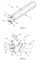
- a cutting tool assembly 10 comprised of a tool holder 12 and a right-hand tool head 14 with a cutting insert 16 removably secured therein.
- the tool holder 12 and tool head 14 may be manufactured from hardened steel, and the cutting insert 16 may be manufactured by form pressing and sintering a cemented carbide, such as tungsten carbide, and can be coated or uncoated.
- the tool holder 12 as shown in Figs. 3 to 6 comprises a generally cylindrical shank portion 18 extending in a forward to rearward direction F, R with a peripheral outer surface 20 and a longitudinal axis A, and a front mating end 22.
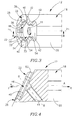
- the front mating end 22 may conceivably be male or female, in the first embodiment of the present invention the front mating end 22 includes a female type tool head coupler 23 in the form of a tool head receiving pocket 24 partially bordered by a raised planar supporting surface 26.
- the supporting surface 26 intersects with the peripheral outer surface 20 of the shank portion 18 and may have four coplanar bearing regions 28, 30, 32, 34 separated by recess regions 36, 38, 40.
- the tool head receiving pocket 24 is comprised of a pocket lower surface 42 having a threaded screw bore 44 therein with a central axis B, and a pocket peripheral surface 46 adjacent the supporting surface 26 having four abutment wall surfaces 48, 50, 52, 54, each inclined at an internal acute first angle ⁇ to the supporting surface 26, where the first, second, third and fourth abutment wall surfaces 48; 50; 52; 54 are adjacent the first, second, third and fourth bearing regions 28; 30; 32; 34, respectively.
- Each of the abutment wall surfaces 48, 50, 52, 54 may provide an 'undercut' in the forward direction F, and the tool head receiving pocket 24 may be 'open' to the peripheral outer surface 20 of the shank portion 18 where the pocket lower surface 42 and pocket peripheral surface 46 each intersect with the peripheral outer surface 20.
- the pocket peripheral surface 46 intersects with the peripheral outer surface 20 and comprises abutment wall surfaces 48, 50, 52, 54, each having the same first angle ⁇ with the supporting surface 26, which enables quick and efficient manufacturing with reduced tooling requirements.
- an 'internal angle' refers to an angle between two features as measured internal to the tool holder 12 or tool head 14, whereas an 'external angle' refers to an angle between two features as measured external to the tool holder 12 or tool head 14.
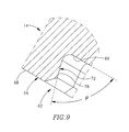
- the tool head 14 as shown in Figs. 7 to 9 has a cutting insert receiving pocket 56 at a forward insert receiving end 57, a generally cylindrical adapter portion 58 with a peripheral exterior surface 60 having the same diameter as the shank portion 18 of the tool holder 12, a nd a rear mating end 62.
- the rear mating end 62 may conceivably be male or female, in the first embodiment of the present invention the rear mating end 62 includes a male type tool holder coupler 63 in the form of an engagement protrusion 64 partially bordered by a lower planar support surface 66, the support surface 66 intersecting with the peripheral exterior surface 60 of the adapter portion 58.
- the engagement protrusion 64 is comprised of a protrusion upper surface 68 having a through bore 70 therein and a protrusion peripheral surface 72 adjacent to the support surface 66 having four abutting wall surfaces 74, 76, 78, 80, each inclined at an external acute second angle ⁇ to the support surface 66.
- the protrusion upper surface 68 and protrusion peripheral surface 72 may each intersect with the peripheral exterior surface 60 of the adapter portion 58.
- the cutting insert 16 which may be indexable, having more than one main cutting edge 82, 84, is removably secured to a planar lower seat surface 86 of the cutting insert receiving pocket 56 by means of an insert fastening member 88.
- the tool holder 12 has a major plane P1 which contains the longitudinal axis A and also the central axis B of the threaded screw bore 44, and the tool holder 12 has mirror symmetry about the major plane P1.
- Each of the four abutment wall surfaces 48, 50, 52, 54 are non-coplanar, and when viewed in a direction of the supporting surface 26 form an external acute third angle ⁇ with the major plane P1, where the first and third abutment wall surfaces 48; 52 form an external acute fourth angle ⁇ with the second and fourth abutment wall surfaces 50; 54, respectively, and where the fourth angle ⁇ is equal to twice the third angle ⁇ , and the first and third abutment wall surfaces 48, 52 and the second and fourth abutment wall surfaces 50, 54 are respectively parallel.
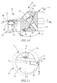
- FIGs. 10 and 11 showing the cutting tool assembly 10.
- the engagement protrusion 64 of the rear mating end 62 is initially positioned in the tool head receiving pocket 24 of the front mating head 22 in a single possible orientation until contact is made between the support surface 66 and the supporting surface 26. Then the tool head 14 is slid into a final assembly position relative to the tool holder 12 where the generally cylindrical adapter portion 58 of the tool head 14 is aligned with the generally cylindrical shank portion 18 of the tool holder 12, and the through bore 70 of the engagement protrusion 64 is aligned with the central axis B of the tool head receiving pocket 24.
- a fastening screw member 90 is then inserted into the through bore 70 and tightened into the threaded screw bore 44 to firmly secure the tool head 14 to the tool holder 12.
- Manufacturing tolerances associated with production of the tool holder 12 and the tool head 14, and operational cutting forces acting on the cutting insert 16 and transmitted through the cutting tool assembly 10 may contribute to acceptably reduce the number of abutting surfaces in contact with abutment surfaces to a minimum of three.
- a minor plane P2 containing the longitudinal axis A and intersecting the operative main cutting edge 82 is perpendicular to the major plane P1
- a main cutting force component Ft tangential to a rotating workpiece 92 is directed parallel to the major plane P1 and perpendicular to the minor plane P2.
- the planar supporting surface 26 being perpendicular to the major plane P1 and inclined at an oblique fifth angle ⁇ to the longitudinal axis A, the main cutting force component Ft is transmitted through both the bearing regions 28, 30, 32, 34 of the supporting surface 26 and the abutment wall surfaces 48, 50, 52, 54 of the tool head receiving pocket 24, at the front mating end 22 of the tool holder 12.
- Inclination of the planar supporting surface 26 at the oblique fifth angle ⁇ to the longitudinal axis A also increases the 'undercut' provided by the abutment wall surfaces 48, 50, 52, 54 of the tool head receiving pocket 24 in the forward direction F, such that forces directed in a forward direction F tending to separate the tool head 14 from the tool holder 12 are transmitted through both the fastening screw member 90 and the abutment wall surfaces 48, 50, 52, 54 of the tool head receiving pocket 24, at the front mating end 22 of the tool holder 12.
- Inclination of the planar supporting surface 26 at the oblique fifth angle ⁇ to the longitudinal axis A also provides a greater supporting surface area in comparison to a supporting surface perpendicular to the longitudinal axis A, for a same diameter shank portion 18.
- the tool holder 12 having mirror symmetry about the major plane P1 means that when the right-hand tool head 14 is exchanged for an equivalent left-hand tool head (not shown), the main cutting force component Ft is also transmitted through both the bearing regions 28, 30, 32, 34 of the supporting surface 26 and the abutment wall surfaces 48, 50, 52, 54 of the tool head receiving pocket 24 in a mirror symmetrical way about the major plane P1.
- the central axis B of the threaded screw bore 44 extends from the pocket lower surface 42 in a direction transverse to the longitudinal axis A and is inclined at an oblique sixth angle ⁇ to the planar supporting surface 26, ensuring that a lateral component of a tightening force from the fastening screw member 90 is directed between the four abutting wall surfaces 74, 76, 78, 80 of the rear mating end 62 of the tool head 14 and the four abutment wall surfaces 48, 50, 52, 54 of the front mating end 22 of the tool holder 12. Also, the central axis B of the threaded screw bore 44 intersects with the minor plane P2, ensuring that a component of the tightening force from the fastening screw member 90 i s directed in the same direction as the main cutting force component, Ft.
- FIG. 12 A second embodiment of the present invention will now be described referring to Figs. 12 to 15 , showing a cutting tool assembly 110 comprising a tool holder 112 having a front mating end 122 and a tool head 114 having a rear mating end 162.
- the front mating end 122 of the tool holder 112 includes a male type tool head coupler 123 in the form of an engagement protrusion 124 partially bordered by a lower planar supporting surface 126, and the rear mating end 162 of the tool head 114 includes a female type tool holder coupler 163 in the form of a tool holder receiving pocket 164 partially bordered by a raised planar support surface 166.
- the engagement protrusion 124 may have a protrusion peripheral surface 146 including two separate protrusion peripheral portions 193, 194, where each protrusion peripheral portion 193, 194 is delimited by the peripheral outer surface 20 of the shank portion 18 of the tool holder 112 and has two abutment wall surfaces 148, 152 and 150, 154, respectively.
- the tool holder receiving pocket 164 may have a pocket peripheral surface 172 including two separate pocket peripheral portions 195, 196, where each pocket peripheral portion 195, 196 is delimited by the peripheral exterior surface 60 of the adapter portion 58 of the tool head 114 and has two abutting wall surfaces 174, 178 and 176, 180, respectively.
- the engagement protrusion 124 of the front mating end 122 is initially positioned in the tool holder receiving pocket 164 of the rear mating end 162 in a single possible orientation until contact is made between the supporting surface 126 and the support surface 166. Then the tool head 114 is then slid into a final assembly position relative to the tool holder 112.
Landscapes
- Engineering & Computer Science (AREA)
- Mechanical Engineering (AREA)
- Cutting Tools, Boring Holders, And Turrets (AREA)
- Milling Processes (AREA)
- Knives (AREA)
Claims (15)
- Ensemble d'outil de coupe (10, 110) pour l'usinage d'une pièce (92), comprenant :un porte-outil (12, 112) avec un axe longitudinal A s'étendant en direction avant à arrière (F, R) et avec une surface périphérique extérieure (20) et une extrémité d'accouplement avant (22, 122), etune tête d'outil (14, 114) avec une extrémité d'accouplement arrière (62, 162) et une extrémité de réception de plaquette avant (57) avec une plaquette de coupe (16) fixée de manière amovible à l'intérieur de celle-ci,l'extrémité d'accouplement avant (22, 122) du porte-outil (12, 112) comprenant :un coupleur (23, 123) de tête d'outil de type mâle ou femelle incluant un alésage fileté (44) avec un axe central B, et une pluralité de surfaces de butée de paroi (48, 148 ; 50, 150 ; 52, 152 ; 54, 154) adjacentes à une surface de support plane (26, 126),l'extrémité d'accouplement arrière (62, 162) de la tête d'outil (14, 114) comprenant :un coupleur (63, 163) de porte-outil de type mâle ou femelle incluant un alésage traversant (70), et une pluralité de surfaces de contact de paroi (74, 174 ; 76, 176 ; 78, 178 ; 80, 180) adjacentes à une surface d'appui plane (66, 166),où la surface d'appui (66, 166) est en contact avec la surface de support (26, 126), au moins trois surfaces de la pluralité de surfaces de contact de paroi (74, 174 ; 76, 176 ; 78, 178 ; 80, 180) sont en contact avec au moins trois surfaces de la pluralité de surfaces de butée de paroi (48, 148 ; 50, 150 ; 52, 152 ; 54, 154), et où un élément de fixation à vis (90) s'étend dans l'alésage traversant (70) et a prise dans l'alésage fileté (44),
caractérisé en ce que les au moins trois surfaces de la pluralité de surfaces de butée de paroi (48, 148 ; 50, 150 ; 52, 152 ; 54, 154) ne sont pas coplanaires et où, vues dans la direction de la surface de support (26, 126), elles sont inclinées suivant un troisième angle aigu α par rapport à un plan principal P1 comprenant l'axe longitudinal A. - Ensemble d'outil de coupe (10) selon la revendication 1, où le coupleur (23) de tête d'outil est de type femelle avec la forme d'une poche de réception (24) de tête d'outil, et où le coupleur (63) de porte-outil est de type mâle avec la forme d'une saillie d'engrènement (64).
- Ensemble d'outil de coupe (10) selon la revendication 2, où la surface de support plane (26) est une surface supérieure bordant au moins en partie la poche de réception (24) de tête d'outil et/ou
où la surface d'appui plane (66) est une surface inférieure bordant au moins en partie la saillie d'engrènement (64). - Ensemble d'outil de coupe (10) selon la revendication 2 ou la revendication 3, où la poche de réception (24) de tête d'outil présente une surface inférieure (42) de poche intersectant la surface périphérique extérieure (20), et/ou
où une seule orientation de la saillie d'engrènement (64) est possible à l'intérieur de la poche de réception (24) de tête d'outil. - Ensemble d'outil de coupe (10, 110) selon l'une des revendications précédentes, où deux des au moins trois surfaces de la pluralité de surfaces de butée de paroi (48, 148 ; 50, 150 ; 52, 152 ; 54, 154) sont parallèles, et/ou
où, vues dans la direction de la surface de support (26, 126), deux des au moins trois surfaces de la pluralité de surfaces de butée de paroi (48, 148 ; 50, 150 ; 52, 152 ; 54, 154) forment un quatrième angle σ, et où le quatrième angle σ est égal au double du troisième angle α. - Ensemble d'outil de coupe (10, 110) selon l'une des revendications 1 à 5, où les au moins trois surfaces de la pluralité de surfaces de butée de paroi (48, 148 ; 50, 150 ; 52, 152 ; 54, 154) sont inclinées suivant un premier angle aigu β par rapport à la surface de support plane (26, 126), et
où les au moins trois surfaces de la pluralité de surface de contact de paroi (74, 174 ; 76, 176 ; 78, 178 ; 80, 180) sont inclinées suivant un deuxième angle aigu φ par rapport à la surface d'appui plane (66, 166), et où le deuxième angle φ est sensiblement égal au premier angle β. - Ensemble d'outil de coupe (10, 110) selon l'une des revendications précédentes, où la surface de support plane (26, 126) est inclinée suivant un cinquième angle oblique γ par rapport à l'axe longitudinal A, et/ou
où la surface de support plane (26, 126) intersecte la surface périphérique extérieure (20) du porte-outil (12, 112). - Ensemble d'outil de coupe (10, 110) selon l'une des revendications précédentes, où quatre surfaces de contact de paroi (74, 174 ; 76, 176 ; 78, 178 ; 80, 180) sont en contact avec quatre surfaces de butée de paroi (48, 148 ; 50, 150 ; 52, 152 ; 54, 154).
- Ensemble d'outil de coupe (10, 110) selon l'une des revendications précédentes, où le porte-outil (12, 112) est à symétrie spéculaire par rapport au plan principal P1.
- Ensemble d'outil de coupe (10, 110) selon l'une des revendications précédentes, où l'axe central B de l'alésage fileté (44) intersecte le plan principal P1 et s'étend dans une direction transversale à l'axe longitudinal A, et/ou
où l'axe central B de l'alésage fileté (44) est incliné suivant un sixième angle oblique δ par rapport à la surface de support plane (26, 126). - Ensemble d'outil de coupe (10, 110) selon l'une des revendications précédentes, où un plan secondaire P2 comprenant l'axe longitudinal A et intersectant une arête de coupe principale (82) fonctionnelle de la plaquette de coupe (16) est perpendiculaire au plan principal P1, et
où l'axe central B intersecte le plan secondaire P2. - Ensemble d'outil de coupe (10) selon l'une des revendications précédentes, où la surface de support plane (26) comprend quatre zones de palier coplanaires (28, 30, 32, 34).
- Ensemble d'outil de coupe (110) selon l'une des revendications précédentes, où le coupleur (123) de tête d'outil est de type mâle avec la forme d'une saillie d'engrènement (124), et où le coupleur (163) de porte-outil est de type femelle avec la forme d'une poche de réception (164) de porte-outil.
- Ensemble d'outil de coupe (110) selon la revendication 13, où la saillie d'engrènement (124) présente une surface périphérique (146) de saillie comprenant deux parties périphériques (193, 194) de saillie séparées.
- Ensemble d'outil de coupe (110) selon la revendication 14, où chaque partie périphérique (193, 194) de saillie est délimitée par la surface périphérique extérieure (20) et présente deux surfaces de butée de paroi (148, 152 et 150, 154).
Priority Applications (1)
| Application Number | Priority Date | Filing Date | Title |
|---|---|---|---|
| PL10718292T PL2416911T3 (pl) | 2009-04-05 | 2010-03-10 | Zespół wkładki skrawającej oraz jej uchwyt narzędziowy |
Applications Claiming Priority (2)
| Application Number | Priority Date | Filing Date | Title |
|---|---|---|---|
| IL197899A IL197899A (en) | 2009-04-05 | 2009-04-05 | Cutting tool and tool holder for it |
| PCT/IL2010/000196 WO2010116352A1 (fr) | 2009-04-05 | 2010-03-10 | Ensemble outil de coupe et porte-outil s'y rapportant |
Publications (2)
| Publication Number | Publication Date |
|---|---|
| EP2416911A1 EP2416911A1 (fr) | 2012-02-15 |
| EP2416911B1 true EP2416911B1 (fr) | 2014-12-24 |
Family
ID=42113655
Family Applications (1)
| Application Number | Title | Priority Date | Filing Date |
|---|---|---|---|
| EP10718292.5A Active EP2416911B1 (fr) | 2009-04-05 | 2010-03-10 | Ensemble outil de coupe et porte-outil s'y rapportant |
Country Status (13)
| Country | Link |
|---|---|
| US (1) | US8479622B2 (fr) |
| EP (1) | EP2416911B1 (fr) |
| JP (1) | JP5580400B2 (fr) |
| KR (1) | KR101670108B1 (fr) |
| CN (1) | CN102378658B (fr) |
| BR (1) | BRPI1012227B8 (fr) |
| CA (1) | CA2754071C (fr) |
| ES (1) | ES2527682T3 (fr) |
| IL (1) | IL197899A (fr) |
| PL (1) | PL2416911T3 (fr) |
| PT (1) | PT2416911E (fr) |
| RU (1) | RU2509628C2 (fr) |
| WO (1) | WO2010116352A1 (fr) |
Families Citing this family (24)
| Publication number | Priority date | Publication date | Assignee | Title |
|---|---|---|---|---|
| CA2844026A1 (fr) * | 2011-08-02 | 2013-02-07 | Iscar Ltd. | Dispositif de fixation d'outil de coupe modulaire et son mecanisme de serrage |
| EP2581157B1 (fr) | 2011-10-11 | 2020-04-01 | VARGUS Ltd. | Outil de découpe pour opérations de rainurage ou de partition |
| US8708613B2 (en) * | 2012-04-10 | 2014-04-29 | Iscar, Ltd. | Left-handed and right-handed cutting tool |
| US8678716B2 (en) * | 2012-04-19 | 2014-03-25 | Iscar, Ltd. | Cutting tool assembly with removable tool head |
| SE538245C2 (sv) | 2012-05-07 | 2016-04-12 | Whizcut Of Sweden Ab | Hållare för skärverktyg med justerbar höjd |
| BR112015010132B1 (pt) * | 2012-11-09 | 2021-09-21 | The Gleason Works | Cabeçote de cortador de face de engrenagem cônica para fresagem e faceamento de engrenagens cônicas e hipoides e método de retificação pelo menos uma lâmina de corte posicionada em um cabeçote de cortador de face de engrenagem cônica |
| CN104853871B (zh) * | 2012-12-14 | 2017-11-17 | 格里森工场 | 具有方形或矩形条形刀片的径向可调整性的齿轮刀具 |
| FR3003783B1 (fr) * | 2013-03-29 | 2015-10-30 | Faurecia Sieges Dautomobile | Assemblage d'outil sur porte outil pour machine outil |
| US9266174B2 (en) * | 2013-06-10 | 2016-02-23 | sp3 Cutting Tools, Inc. | Cutting tool |
| USD753737S1 (en) * | 2013-10-24 | 2016-04-12 | Sumitomo Electric Hardmetal Corp. | Cutting tool |
| US9339873B2 (en) * | 2013-12-11 | 2016-05-17 | Iscar, Ltd. | Cutting insert having a dovetail anti-slip arrangement |
| US9702385B2 (en) * | 2014-05-15 | 2017-07-11 | Iscar, Ltd. | Machine tool assembly configured for swift disassembly |
| DE102014008778A1 (de) | 2014-06-12 | 2015-12-17 | Iscar Ltd. | Zur schnellen Demontage konfigurierte Maschinenwerkzeug-Baueinheit |
| DE202015105073U1 (de) * | 2015-09-25 | 2016-12-28 | Bernd Dutschke | Drehhaltervorrichtung für Drehmaschinen |
| EP3246117A1 (fr) * | 2016-05-20 | 2017-11-22 | Seco Tools Ab | Outil de coupe et cale |
| EP3456446A1 (fr) * | 2017-09-15 | 2019-03-20 | Sandvik Intellectual Property AB | Assemblage de pièces d'outil de coupe |
| CN109692978A (zh) * | 2018-12-28 | 2019-04-30 | 武汉协和齿环有限公司 | 同步器齿环车加工复合车刀及同步器齿环加工方法 |
| CN110434360B (zh) * | 2019-07-16 | 2020-12-29 | 无锡市亨达电机有限公司 | 一种铝壳机座加工用非标三刀头刀柄结构 |
| CN110961663A (zh) * | 2019-11-22 | 2020-04-07 | 辽宁程瑞砂轮有限公司 | 一种用于砂轮精加工的孔径车削刀具及其加工方法 |
| US11897038B2 (en) * | 2020-09-30 | 2024-02-13 | Iscar, Ltd. | Curved face grooving blade and face grooving holder therefor |
| JP7004107B1 (ja) * | 2021-07-02 | 2022-01-21 | 株式会社タンガロイ | ホルダおよび切削工具 |
| CN114143998A (zh) * | 2021-11-30 | 2022-03-04 | 上海豪承信息技术有限公司 | 电子组件及移动终端 |
| JP7095822B1 (ja) * | 2022-01-12 | 2022-07-05 | 株式会社タンガロイ | ヘッド交換式切削工具における工具ヘッド |
| JP7253157B1 (ja) | 2022-06-22 | 2023-04-06 | 株式会社タンガロイ | シャンクおよびこれを備えた切削工具 |
Family Cites Families (18)
| Publication number | Priority date | Publication date | Assignee | Title |
|---|---|---|---|---|
| US3002405A (en) * | 1958-04-17 | 1961-10-03 | Heftler Maurice Ben | Cutting tools |
| US2924129A (en) * | 1958-09-22 | 1960-02-09 | George A Munro | Adjustable boring bar |
| US3289273A (en) * | 1964-04-01 | 1966-12-06 | Gerard P Artaud | Cutting tool assembly |
| US4102591A (en) * | 1976-12-30 | 1978-07-25 | The Warner & Swasey Company | Cutting tool |
| SU1006070A1 (ru) * | 1980-07-10 | 1983-03-23 | Предприятие П/Я В-8772 | Резец |
| DE3448086C2 (fr) * | 1984-01-26 | 1991-12-19 | Hartmetall-Werkzeugfabrik Paul Horn Gmbh, 7400 Tuebingen, De | |
| SU1553257A1 (ru) * | 1987-06-17 | 1990-03-30 | Предприятие П/Я А-1891 | Сборный резец |
| DE4140301A1 (de) * | 1991-12-06 | 1993-06-09 | Komet Stahlhalter- Und Werkzeugfabrik Robert Breuning Gmbh, 7122 Besigheim, De | Drehwerkzeug |
| JPH08507003A (ja) * | 1993-04-14 | 1996-07-30 | ツェトル.ゲゼルシャフト.ミット.ベシュレンクテル.ハフツング.ツェーエヌツェー.プレツィシオンズ−ウント.ゾンデルウエルクツオイグ | フライス工具 |
| SE511429C2 (sv) * | 1996-09-13 | 1999-09-27 | Seco Tools Ab | Verktyg, skärdel, verktygskropp för skärande bearbetning samt metod för montering av skärdel till verktygskropp |
| IL120948A0 (en) * | 1997-05-29 | 1997-09-30 | Iscar Ltd | Cutting tool assembly |
| SE516003C2 (sv) * | 2000-03-02 | 2001-11-05 | Sandvik Ab | Verktyg med snedställda monteringsytor mellan hållar- och verktygsdel |
| JP2001328012A (ja) * | 2000-05-19 | 2001-11-27 | Daishowa Seiki Co Ltd | 切削工具 |
| SE523747C2 (sv) * | 2001-08-31 | 2004-05-11 | Sandvik Ab | Verktyg för spånavskiljande bearbetning med vinklad skärhållare |
| IL148535A (en) * | 2002-03-06 | 2009-02-11 | Gil Hecht | Metal cutting tool |
| DE50313625D1 (de) * | 2002-10-25 | 2011-06-01 | Syntronic Ag | Werkzeugaufnahme |
| US7240593B2 (en) * | 2005-04-19 | 2007-07-10 | Roger Little | Miniature cutting insert holder |
| DE102006035182A1 (de) * | 2006-07-29 | 2008-01-31 | Hartmetall-Werkzeugfabrik Paul Horn Gmbh | Werkzeugsystem |
-
2009
- 2009-04-05 IL IL197899A patent/IL197899A/en active IP Right Grant
-
2010
- 2010-03-10 CN CN2010800152748A patent/CN102378658B/zh active Active
- 2010-03-10 RU RU2011144856/02A patent/RU2509628C2/ru active
- 2010-03-10 BR BRPI1012227A patent/BRPI1012227B8/pt active IP Right Grant
- 2010-03-10 PL PL10718292T patent/PL2416911T3/pl unknown
- 2010-03-10 JP JP2012502873A patent/JP5580400B2/ja active Active
- 2010-03-10 PT PT107182925T patent/PT2416911E/pt unknown
- 2010-03-10 CA CA2754071A patent/CA2754071C/fr active Active
- 2010-03-10 EP EP10718292.5A patent/EP2416911B1/fr active Active
- 2010-03-10 ES ES10718292.5T patent/ES2527682T3/es active Active
- 2010-03-10 WO PCT/IL2010/000196 patent/WO2010116352A1/fr active Application Filing
- 2010-03-10 KR KR1020117023231A patent/KR101670108B1/ko active IP Right Grant
- 2010-03-31 US US12/751,735 patent/US8479622B2/en active Active
Also Published As
| Publication number | Publication date |
|---|---|
| BRPI1012227B8 (pt) | 2021-01-19 |
| BRPI1012227B1 (pt) | 2020-02-27 |
| RU2011144856A (ru) | 2013-05-20 |
| PL2416911T3 (pl) | 2015-05-29 |
| EP2416911A1 (fr) | 2012-02-15 |
| CA2754071C (fr) | 2017-05-02 |
| IL197899A0 (en) | 2009-12-24 |
| CA2754071A1 (fr) | 2010-10-14 |
| CN102378658A (zh) | 2012-03-14 |
| US20100254774A1 (en) | 2010-10-07 |
| PT2416911E (pt) | 2015-02-13 |
| US8479622B2 (en) | 2013-07-09 |
| ES2527682T3 (es) | 2015-01-28 |
| KR20110135399A (ko) | 2011-12-16 |
| CN102378658B (zh) | 2013-09-11 |
| JP5580400B2 (ja) | 2014-08-27 |
| JP2012522651A (ja) | 2012-09-27 |
| BRPI1012227A2 (pt) | 2016-03-29 |
| RU2509628C2 (ru) | 2014-03-20 |
| IL197899A (en) | 2013-02-28 |
| KR101670108B1 (ko) | 2016-10-27 |
| WO2010116352A1 (fr) | 2010-10-14 |
Similar Documents
| Publication | Publication Date | Title |
|---|---|---|
| EP2416911B1 (fr) | Ensemble outil de coupe et porte-outil s'y rapportant | |
| EP2176020B1 (fr) | Outil de coupe et corps d'outil | |
| US7419336B2 (en) | Milling insert and a milling tool, as well as a shim plate for such tools | |
| US20060051167A1 (en) | Toolholder and cutting insert for a toolholder assembly | |
| EP2558235B1 (fr) | Outil de coupe | |
| EP1881878B1 (fr) | Porte-outil et ensemble de porte-outil | |
| EP2401103B1 (fr) | Outil de coupe avec mécanisme de réglage | |
| US9669467B2 (en) | Tool system | |
| US20190030613A1 (en) | Cutting tool | |
| EP2316597B1 (fr) | Élément de serrage | |
| JP3286836B2 (ja) | スローアウェイバイト及びそのシャンク | |
| EP0638385A1 (fr) | Outil de coupe | |
| EP3199274B1 (fr) | Outil de découpage | |
| JPH10118821A (ja) | 切削工具 |
Legal Events
| Date | Code | Title | Description |
|---|---|---|---|
| PUAI | Public reference made under article 153(3) epc to a published international application that has entered the european phase |
Free format text: ORIGINAL CODE: 0009012 |
|
| 17P | Request for examination filed |
Effective date: 20111103 |
|
| AK | Designated contracting states |
Kind code of ref document: A1 Designated state(s): AT BE BG CH CY CZ DE DK EE ES FI FR GB GR HR HU IE IS IT LI LT LU LV MC MK MT NL NO PL PT RO SE SI SK SM TR |
|
| DAX | Request for extension of the european patent (deleted) | ||
| GRAP | Despatch of communication of intention to grant a patent |
Free format text: ORIGINAL CODE: EPIDOSNIGR1 |
|
| INTG | Intention to grant announced |
Effective date: 20140728 |
|
| GRAS | Grant fee paid |
Free format text: ORIGINAL CODE: EPIDOSNIGR3 |
|
| GRAA | (expected) grant |
Free format text: ORIGINAL CODE: 0009210 |
|
| AK | Designated contracting states |
Kind code of ref document: B1 Designated state(s): AT BE BG CH CY CZ DE DK EE ES FI FR GB GR HR HU IE IS IT LI LT LU LV MC MK MT NL NO PL PT RO SE SI SK SM TR |
|
| REG | Reference to a national code |
Ref country code: GB Ref legal event code: FG4D |
|
| REG | Reference to a national code |
Ref country code: CH Ref legal event code: EP |
|
| REG | Reference to a national code |
Ref country code: IE Ref legal event code: FG4D |
|
| REG | Reference to a national code |
Ref country code: AT Ref legal event code: REF Ref document number: 702881 Country of ref document: AT Kind code of ref document: T Effective date: 20150115 |
|
| REG | Reference to a national code |
Ref country code: ES Ref legal event code: FG2A Ref document number: 2527682 Country of ref document: ES Kind code of ref document: T3 Effective date: 20150128 |
|
| REG | Reference to a national code |
Ref country code: DE Ref legal event code: R096 Ref document number: 602010021244 Country of ref document: DE Effective date: 20150212 |
|
| REG | Reference to a national code |
Ref country code: PT Ref legal event code: SC4A Free format text: AVAILABILITY OF NATIONAL TRANSLATION Effective date: 20150205 |
|
| REG | Reference to a national code |
Ref country code: SE Ref legal event code: TRGR |
|
| REG | Reference to a national code |
Ref country code: NL Ref legal event code: VDEP Effective date: 20141224 |
|
| PG25 | Lapsed in a contracting state [announced via postgrant information from national office to epo] |
Ref country code: LT Free format text: LAPSE BECAUSE OF FAILURE TO SUBMIT A TRANSLATION OF THE DESCRIPTION OR TO PAY THE FEE WITHIN THE PRESCRIBED TIME-LIMIT Effective date: 20141224 Ref country code: FI Free format text: LAPSE BECAUSE OF FAILURE TO SUBMIT A TRANSLATION OF THE DESCRIPTION OR TO PAY THE FEE WITHIN THE PRESCRIBED TIME-LIMIT Effective date: 20141224 Ref country code: NO Free format text: LAPSE BECAUSE OF FAILURE TO SUBMIT A TRANSLATION OF THE DESCRIPTION OR TO PAY THE FEE WITHIN THE PRESCRIBED TIME-LIMIT Effective date: 20150324 |
|
| REG | Reference to a national code |
Ref country code: LT Ref legal event code: MG4D |
|
| PG25 | Lapsed in a contracting state [announced via postgrant information from national office to epo] |
Ref country code: LV Free format text: LAPSE BECAUSE OF FAILURE TO SUBMIT A TRANSLATION OF THE DESCRIPTION OR TO PAY THE FEE WITHIN THE PRESCRIBED TIME-LIMIT Effective date: 20141224 Ref country code: GR Free format text: LAPSE BECAUSE OF FAILURE TO SUBMIT A TRANSLATION OF THE DESCRIPTION OR TO PAY THE FEE WITHIN THE PRESCRIBED TIME-LIMIT Effective date: 20150325 Ref country code: HR Free format text: LAPSE BECAUSE OF FAILURE TO SUBMIT A TRANSLATION OF THE DESCRIPTION OR TO PAY THE FEE WITHIN THE PRESCRIBED TIME-LIMIT Effective date: 20141224 |
|
| REG | Reference to a national code |
Ref country code: PL Ref legal event code: T3 |
|
| PG25 | Lapsed in a contracting state [announced via postgrant information from national office to epo] |
Ref country code: NL Free format text: LAPSE BECAUSE OF FAILURE TO SUBMIT A TRANSLATION OF THE DESCRIPTION OR TO PAY THE FEE WITHIN THE PRESCRIBED TIME-LIMIT Effective date: 20141224 |
|
| PG25 | Lapsed in a contracting state [announced via postgrant information from national office to epo] |
Ref country code: RO Free format text: LAPSE BECAUSE OF FAILURE TO SUBMIT A TRANSLATION OF THE DESCRIPTION OR TO PAY THE FEE WITHIN THE PRESCRIBED TIME-LIMIT Effective date: 20141224 Ref country code: SK Free format text: LAPSE BECAUSE OF FAILURE TO SUBMIT A TRANSLATION OF THE DESCRIPTION OR TO PAY THE FEE WITHIN THE PRESCRIBED TIME-LIMIT Effective date: 20141224 Ref country code: EE Free format text: LAPSE BECAUSE OF FAILURE TO SUBMIT A TRANSLATION OF THE DESCRIPTION OR TO PAY THE FEE WITHIN THE PRESCRIBED TIME-LIMIT Effective date: 20141224 |
|
| PG25 | Lapsed in a contracting state [announced via postgrant information from national office to epo] |
Ref country code: IS Free format text: LAPSE BECAUSE OF FAILURE TO SUBMIT A TRANSLATION OF THE DESCRIPTION OR TO PAY THE FEE WITHIN THE PRESCRIBED TIME-LIMIT Effective date: 20150424 |
|
| REG | Reference to a national code |
Ref country code: DE Ref legal event code: R097 Ref document number: 602010021244 Country of ref document: DE |
|
| PG25 | Lapsed in a contracting state [announced via postgrant information from national office to epo] |
Ref country code: DK Free format text: LAPSE BECAUSE OF FAILURE TO SUBMIT A TRANSLATION OF THE DESCRIPTION OR TO PAY THE FEE WITHIN THE PRESCRIBED TIME-LIMIT Effective date: 20141224 Ref country code: LU Free format text: LAPSE BECAUSE OF FAILURE TO SUBMIT A TRANSLATION OF THE DESCRIPTION OR TO PAY THE FEE WITHIN THE PRESCRIBED TIME-LIMIT Effective date: 20150310 Ref country code: MC Free format text: LAPSE BECAUSE OF FAILURE TO SUBMIT A TRANSLATION OF THE DESCRIPTION OR TO PAY THE FEE WITHIN THE PRESCRIBED TIME-LIMIT Effective date: 20141224 |
|
| REG | Reference to a national code |
Ref country code: CH Ref legal event code: PL |
|
| PLBE | No opposition filed within time limit |
Free format text: ORIGINAL CODE: 0009261 |
|
| STAA | Information on the status of an ep patent application or granted ep patent |
Free format text: STATUS: NO OPPOSITION FILED WITHIN TIME LIMIT |
|
| 26N | No opposition filed |
Effective date: 20150925 |
|
| REG | Reference to a national code |
Ref country code: IE Ref legal event code: MM4A |
|
| PG25 | Lapsed in a contracting state [announced via postgrant information from national office to epo] |
Ref country code: CH Free format text: LAPSE BECAUSE OF NON-PAYMENT OF DUE FEES Effective date: 20150331 Ref country code: IE Free format text: LAPSE BECAUSE OF NON-PAYMENT OF DUE FEES Effective date: 20150310 Ref country code: LI Free format text: LAPSE BECAUSE OF NON-PAYMENT OF DUE FEES Effective date: 20150331 |
|
| REG | Reference to a national code |
Ref country code: FR Ref legal event code: PLFP Year of fee payment: 7 |
|
| PG25 | Lapsed in a contracting state [announced via postgrant information from national office to epo] |
Ref country code: SI Free format text: LAPSE BECAUSE OF FAILURE TO SUBMIT A TRANSLATION OF THE DESCRIPTION OR TO PAY THE FEE WITHIN THE PRESCRIBED TIME-LIMIT Effective date: 20141224 |
|
| REG | Reference to a national code |
Ref country code: AT Ref legal event code: UEP Ref document number: 702881 Country of ref document: AT Kind code of ref document: T Effective date: 20141224 |
|
| PG25 | Lapsed in a contracting state [announced via postgrant information from national office to epo] |
Ref country code: BE Free format text: LAPSE BECAUSE OF FAILURE TO SUBMIT A TRANSLATION OF THE DESCRIPTION OR TO PAY THE FEE WITHIN THE PRESCRIBED TIME-LIMIT Effective date: 20141224 |
|
| PG25 | Lapsed in a contracting state [announced via postgrant information from national office to epo] |
Ref country code: MT Free format text: LAPSE BECAUSE OF FAILURE TO SUBMIT A TRANSLATION OF THE DESCRIPTION OR TO PAY THE FEE WITHIN THE PRESCRIBED TIME-LIMIT Effective date: 20141224 |
|
| REG | Reference to a national code |
Ref country code: FR Ref legal event code: PLFP Year of fee payment: 8 |
|
| PG25 | Lapsed in a contracting state [announced via postgrant information from national office to epo] |
Ref country code: BG Free format text: LAPSE BECAUSE OF FAILURE TO SUBMIT A TRANSLATION OF THE DESCRIPTION OR TO PAY THE FEE WITHIN THE PRESCRIBED TIME-LIMIT Effective date: 20141224 Ref country code: SM Free format text: LAPSE BECAUSE OF FAILURE TO SUBMIT A TRANSLATION OF THE DESCRIPTION OR TO PAY THE FEE WITHIN THE PRESCRIBED TIME-LIMIT Effective date: 20141224 Ref country code: HU Free format text: LAPSE BECAUSE OF FAILURE TO SUBMIT A TRANSLATION OF THE DESCRIPTION OR TO PAY THE FEE WITHIN THE PRESCRIBED TIME-LIMIT; INVALID AB INITIO Effective date: 20100310 |
|
| PG25 | Lapsed in a contracting state [announced via postgrant information from national office to epo] |
Ref country code: CY Free format text: LAPSE BECAUSE OF FAILURE TO SUBMIT A TRANSLATION OF THE DESCRIPTION OR TO PAY THE FEE WITHIN THE PRESCRIBED TIME-LIMIT Effective date: 20141224 |
|
| REG | Reference to a national code |
Ref country code: FR Ref legal event code: PLFP Year of fee payment: 9 |
|
| PG25 | Lapsed in a contracting state [announced via postgrant information from national office to epo] |
Ref country code: MK Free format text: LAPSE BECAUSE OF FAILURE TO SUBMIT A TRANSLATION OF THE DESCRIPTION OR TO PAY THE FEE WITHIN THE PRESCRIBED TIME-LIMIT Effective date: 20141224 |
|
| PGFP | Annual fee paid to national office [announced via postgrant information from national office to epo] |
Ref country code: FR Payment date: 20230217 Year of fee payment: 14 Ref country code: AT Payment date: 20230206 Year of fee payment: 14 Ref country code: CZ Payment date: 20230220 Year of fee payment: 14 |
|
| PGFP | Annual fee paid to national office [announced via postgrant information from national office to epo] |
Ref country code: TR Payment date: 20230222 Year of fee payment: 14 Ref country code: SE Payment date: 20230210 Year of fee payment: 14 Ref country code: PL Payment date: 20230119 Year of fee payment: 14 Ref country code: IT Payment date: 20230116 Year of fee payment: 14 |
|
| PGFP | Annual fee paid to national office [announced via postgrant information from national office to epo] |
Ref country code: ES Payment date: 20230425 Year of fee payment: 14 |
|
| PGFP | Annual fee paid to national office [announced via postgrant information from national office to epo] |
Ref country code: AT Payment date: 20240206 Year of fee payment: 15 |
|
| PGFP | Annual fee paid to national office [announced via postgrant information from national office to epo] |
Ref country code: DE Payment date: 20240209 Year of fee payment: 15 Ref country code: CZ Payment date: 20240207 Year of fee payment: 15 Ref country code: PT Payment date: 20240119 Year of fee payment: 15 Ref country code: GB Payment date: 20240207 Year of fee payment: 15 |