EP0979146B1 - Reaktion behälter apparat - Google Patents
Reaktion behälter apparat Download PDFInfo
- Publication number
- EP0979146B1 EP0979146B1 EP98919968A EP98919968A EP0979146B1 EP 0979146 B1 EP0979146 B1 EP 0979146B1 EP 98919968 A EP98919968 A EP 98919968A EP 98919968 A EP98919968 A EP 98919968A EP 0979146 B1 EP0979146 B1 EP 0979146B1
- Authority
- EP
- European Patent Office
- Prior art keywords
- contact
- receptacle apparatus
- receptacles
- limiting element
- receptacle
- Prior art date
- Legal status (The legal status is an assumption and is not a legal conclusion. Google has not performed a legal analysis and makes no representation as to the accuracy of the status listed.)
- Expired - Lifetime
Links
Images


Classifications
-
- B—PERFORMING OPERATIONS; TRANSPORTING
- B01—PHYSICAL OR CHEMICAL PROCESSES OR APPARATUS IN GENERAL
- B01L—CHEMICAL OR PHYSICAL LABORATORY APPARATUS FOR GENERAL USE
- B01L9/00—Supporting devices; Holding devices
- B01L9/06—Test-tube stands; Test-tube holders
-
- B—PERFORMING OPERATIONS; TRANSPORTING
- B01—PHYSICAL OR CHEMICAL PROCESSES OR APPARATUS IN GENERAL
- B01L—CHEMICAL OR PHYSICAL LABORATORY APPARATUS FOR GENERAL USE
- B01L9/00—Supporting devices; Holding devices
- B01L9/54—Supports specially adapted for pipettes and burettes
- B01L9/543—Supports specially adapted for pipettes and burettes for disposable pipette tips, e.g. racks or cassettes
-
- G—PHYSICS
- G01—MEASURING; TESTING
- G01N—INVESTIGATING OR ANALYSING MATERIALS BY DETERMINING THEIR CHEMICAL OR PHYSICAL PROPERTIES
- G01N33/00—Investigating or analysing materials by specific methods not covered by groups G01N1/00 - G01N31/00
- G01N33/48—Biological material, e.g. blood, urine; Haemocytometers
- G01N33/50—Chemical analysis of biological material, e.g. blood, urine; Testing involving biospecific ligand binding methods; Immunological testing
- G01N33/53—Immunoassay; Biospecific binding assay; Materials therefor
- G01N33/5302—Apparatus specially adapted for immunological test procedures
- G01N33/5304—Reaction vessels, e.g. agglutination plates
-
- G—PHYSICS
- G01—MEASURING; TESTING
- G01N—INVESTIGATING OR ANALYSING MATERIALS BY DETERMINING THEIR CHEMICAL OR PHYSICAL PROPERTIES
- G01N35/00—Automatic analysis not limited to methods or materials provided for in any single one of groups G01N1/00 - G01N33/00; Handling materials therefor
- G01N35/02—Automatic analysis not limited to methods or materials provided for in any single one of groups G01N1/00 - G01N33/00; Handling materials therefor using a plurality of sample containers moved by a conveyor system past one or more treatment or analysis stations
- G01N35/026—Automatic analysis not limited to methods or materials provided for in any single one of groups G01N1/00 - G01N33/00; Handling materials therefor using a plurality of sample containers moved by a conveyor system past one or more treatment or analysis stations having blocks or racks of reaction cells or cuvettes
-
- G—PHYSICS
- G01—MEASURING; TESTING
- G01N—INVESTIGATING OR ANALYSING MATERIALS BY DETERMINING THEIR CHEMICAL OR PHYSICAL PROPERTIES
- G01N35/00—Automatic analysis not limited to methods or materials provided for in any single one of groups G01N1/00 - G01N33/00; Handling materials therefor
- G01N2035/00178—Special arrangements of analysers
- G01N2035/00277—Special precautions to avoid contamination (e.g. enclosures, glove- boxes, sealed sample carriers, disposal of contaminated material)
-
- G—PHYSICS
- G01—MEASURING; TESTING
- G01N—INVESTIGATING OR ANALYSING MATERIALS BY DETERMINING THEIR CHEMICAL OR PHYSICAL PROPERTIES
- G01N35/00—Automatic analysis not limited to methods or materials provided for in any single one of groups G01N1/00 - G01N33/00; Handling materials therefor
- G01N35/10—Devices for transferring samples or any liquids to, in, or from, the analysis apparatus, e.g. suction devices, injection devices
- G01N2035/1027—General features of the devices
- G01N2035/103—General features of the devices using disposable tips
-
- G—PHYSICS
- G01—MEASURING; TESTING
- G01N—INVESTIGATING OR ANALYSING MATERIALS BY DETERMINING THEIR CHEMICAL OR PHYSICAL PROPERTIES
- G01N35/00—Automatic analysis not limited to methods or materials provided for in any single one of groups G01N1/00 - G01N33/00; Handling materials therefor
- G01N35/10—Devices for transferring samples or any liquids to, in, or from, the analysis apparatus, e.g. suction devices, injection devices
- G01N35/1081—Devices for transferring samples or any liquids to, in, or from, the analysis apparatus, e.g. suction devices, injection devices characterised by the means for relatively moving the transfer device and the containers in an horizontal plane
- G01N35/1083—Devices for transferring samples or any liquids to, in, or from, the analysis apparatus, e.g. suction devices, injection devices characterised by the means for relatively moving the transfer device and the containers in an horizontal plane with one horizontal degree of freedom
- G01N2035/1086—Cylindrical, e.g. variable angle
-
- Y—GENERAL TAGGING OF NEW TECHNOLOGICAL DEVELOPMENTS; GENERAL TAGGING OF CROSS-SECTIONAL TECHNOLOGIES SPANNING OVER SEVERAL SECTIONS OF THE IPC; TECHNICAL SUBJECTS COVERED BY FORMER USPC CROSS-REFERENCE ART COLLECTIONS [XRACs] AND DIGESTS
- Y10—TECHNICAL SUBJECTS COVERED BY FORMER USPC
- Y10T—TECHNICAL SUBJECTS COVERED BY FORMER US CLASSIFICATION
- Y10T436/00—Chemistry: analytical and immunological testing
- Y10T436/11—Automated chemical analysis
- Y10T436/113332—Automated chemical analysis with conveyance of sample along a test line in a container or rack
Definitions
- the present invention relates to reaction receptacles useful for containing chemical or biological substances.
- Reaction receptacles or test tubes are commonly used in the chemical and biological arts to perform a variety of types of assays in a contained space. Assays that commonly have one or more steps performed in reaction receptacles include chemical reactions, immunoassays, and nucleic acid-based assays. Examples of such reactions and assays are thoroughly described in the available literature and are well known to those skilled in the art. While reaction receptacles are generally manufactured and sold as individual units or test tubes, it is common for practitioners to use holding racks to conveniently and collectively organize a group of reaction receptacles for performing multiple assays simultaneously or sequentially. In some instances, multiple reaction receptacles are assembled as a unitary piece.
- a substance transfer device is used to dispense solutions into or remove solutions from reaction receptacles.
- the most familiar substance transfer devices are pipettes and aspirators including one or more tubular elements through which fluids are dispensed or withdrawn.
- substance transfer devices are used in conducting a group of independent assays at about the same time or in close proximity to one another, there is always the concern that a substance transfer device will inadvertently serve as a vehicle in transferring substances or contaminants between reaction receptacles. An additional concern is that the practitioner will improperly add substances into or remove substances from a reaction receptacle.
- One way to limit opportunities for cross-contamination is to reduce the amount of surface area on the substance transfer device that can come into contact with the contents of a reaction receptacle.
- This objective can be achieved by using a contact-limiting element, such as a pipette tip, which essentially serves as a barrier between the outer surface of the pipette and the contents of a reaction receptacle.
- a contact-limiting element such as a pipette tip, which essentially serves as a barrier between the outer surface of the pipette and the contents of a reaction receptacle.
- a contact-limiting element such as a pipette tip, which essentially serves as a barrier between the outer surface of the pipette and the contents of a reaction receptacle.
- reaction receptacles Another problem presented by conventional reaction receptacles is that they come packaged as individual test tubes that are not amenable to manipulation by an automated assay instrument. Individual reaction receptacles hinder throughput efficiency since the practitioner and instrument must each handle the reaction receptacles separately. And because conventional reaction receptacles are not provided with any structure that permits them to be manipulated by an automated instrument,.reaction receptacles are generally stationed at one situs within the instrument and are not afforded any automated mobility. This lack of movement imposes.certain architectural limitations and assay inefficiencies since the instrument must be designed around the positioning of the reaction receptacles. Accordingly, there is a need for a reaction receptacle apparatus which can be manipulated by an automated assay instrument, where the apparatus may include one reaction receptacle or plurality of reaction receptacles coupled together as a single operative unit.
- EP-A-0246632 discloses a pipetting device having an automatic mechanism for replacing nozzle tips.
- the pipetting device comprises a supporting frame, a slider mounted on said supporting frame for vertical movement, a power driving means for vertically moving said slider, a pipetting head mounted on said slider, said pipetting head including a pipette, having a lower end fittabie within the upper end of an approximately inverted cone shaped nozzle tip, means for communicating said lower end of said pipette member with an air supply and exhaust means, whereby said nozzle tip may be supplied with air or air may be sucked therefrom.
- a nozzle tipholder comprising a plurality of reaction cells and a nozzle tip, which is associated with each reaction cell.
- US-Patent 4, 824, 641 discloses an improved sample carrier and pipette tips for use in an automated sample handling device.
- This carrier has spaced about the circumference of its body a plurality of apertures for receiving the sample containers.
- the apertures are substantially parallel to the axis of the. circular body of the carrier.
- the apertures are angled in a posture.
- the sample carrier is also adapted to carry a plurality of pipette tips for sequential pick up. by an automated pipette. Pipette tips particularly adapted for automatic pick up are also disclosed.
- a reaction receptacle apparatus can be used to perform chemical or biological assays and comprises a plurality of reaction receptacles for containing substances used in performing such assays.
- the reaction receptacles are operatively coupled to one another, either directly or indirectly, and are capable of interacting with a substance transfer device that dispenses substances into or withdraws substances from said receptacles making up the reaction receptacle apparatus.
- the present invention provides for one or more contact-limiting elements each said contact-limiting element being associated with the reaction receptacle apparatus.
- the contact-limiting elements are constructed and arranged to be operatively engaged by the substance transfer device to limit potentially contaminating contact between at least a portion of the substance transfer device and a potentially contaminating substance that is dispensed into or withdrawn from a reaction receptacle by the substance transfer device.
- Each said contact-limiting element is associated with one or more of the reaction receptacles of the reaction receptacle apparatus.
- the reaction receptacle apparatus is outfitted with one or more contact-limiting element holding structures, each contact-limiting element holding structure being associated with. one of said contact-limiting elements.
- Each of the contact-limiting element holding structures is constructed and arranged to (i) receive and removably hold the associated contact-limiting element in an operative orientation in proximity to the one or more associated receptacles so as to be operatively engageable by the substance transfer device, and (ii) allow the associated contact-limiting element to be removed from the associated contact-limiting element holding structure when the associated contact-limiting element is operatively engaged by the substance transfer device.
- an automated assay instrument can be constructed so that the substance transfer device avoids complex motions and conveniently engages the contact-limiting elements when the reaction receptacle apparatus is brought into an operative position within the instrument.
- An additional benefit is that the instrument does not have to be configured to receive a store of contact-limiting elements, and practitioners are spared having to monitor the volume of contact-limiting elements in an instrument while assays are being run.
- a preferred embodiment of the present invention is a reaction receptacle apparatus including receptacle apparatus manipulating structure to permit manipulation of the apparatus by an automated reaction receptacle manipulating device.
- the receptacle apparatus manipulating structure is constructed and arranged to be engaged by an automated reaction receptacle manipulating device, so that the reaction receptacle apparatus can be robotically manipulated within an automated instrument.
- the reaction receptacle apparatus of this embodiment includes at least one reaction receptacle and may optionally include the contact-limiting elements and associated contact-limiting element holding structures described above.
- a preferred embodiment of a reaction receptacle apparatus according to the present invention is designated generally by the reference character 160.
- the reaction receptacle apparatus 160 comprises a plurality of individual receptacles 162.
- the reaction receptacle apparatus 160 includes five individual receptacles 162, but a reaction receptacle according to the present invention may include any number of receptacles 162, as desired. Ten receptacles 162 are preferred and five receptacles 162 are most preferred.
- Each individual receptacle 162 preferably has a construction similar to that of a conventional test-tube, i.e., a cylindrical body with a circular open mouth 161 and a rounded closed bottom end 163.
- Each individual receptacle can, however, have other shapes, such as rectangular, octagonal, etc., and may have an upper end equipped with a closable lid structure or the like.
- the receptacles may have the same or different shapes and sizes.
- the receptacles 162 are preferably oriented in an aligned arrangement comprising a single row of receptacles 162 and are connected to one another by a connecting rib structure 164 which defines a downwardly facing shoulder 165 extending longitudinally along either side of the reaction receptacle apparatus 160.
- the receptacles 162 may be oriented in a different nonlinear arrangement, or a single reaction receptacle apparatus may comprise more than one row of receptacles 162.
- Reaction receptacle apparatus 160 is preferably a single, integral piece formed of injection molded polypropylene.
- the most preferred polypropylene is sold by Montell Polyolefins, of Wilmington, Delaware, product number PD701NW.
- the Montell material is used because it is readily moldable and is chemically compatible with the preferred biological assays performed in the reaction receptacle apparatus.
- the Montell material experiences a limited number of static discharge events, which is important when the results of the assay performed in the reaction receptacle apparatus are determined by the detection of light emitted by the contents of the apparatus at the conclusion of the assay. Static discharge events can interfere with accurate detection or quantification of the light output.
- An arcuate shield structure 185 provided at one end of the reaction receptacle apparatus 160 includes an upper portion 169 and a lower portion 173.
- a receptacle apparatus manipulating structure 166 adapted to be engaged by a reaction receptacle manipulating device, extends from the shield upper portion 169.
- Receptacle apparatus manipulating structure 166 comprises a laterally extending plate 168. extending from shield upper portion 169 with a transverse piece 167 on the opposite end of the plate 168.
- a gusset wall 183 extends downwardly from lateral plate 168 between shield lower portion 173 and transverse piece 167.
- the shield lower portion 173 and transverse piece 167 have mutually facing convex surfaces.
- the reaction receptacle apparatus 160 is preferably engaged by manipulating devices and other components, as will be described below, by moving an engaging member of the manipulating device laterally (in the direction "A") into a space 50 between the shield lower portion 173 and the transverse piece 167.
- the convex surfaces of the shield lower portion 173 and transverse piece 167 provide for wider points of entry for an engaging member undergoing a lateral relative motion into the space 50.
- Vertically extending, raised arcuate ridges 171, 172 may be provided in the middle of the convex surfaces.of the transverse piece 167 and shield lower portion 173, respectively. The purpose of ridges 171, 172 will be described below.
- a label-receiving structure 174 provided on an end of the reaction receptacle apparatus 160 opposite receptacle apparatus manipulating structure 166 preferably includes an upper portion 71 and a lower portion 75, which together present a flat label-receiving surface 175.
- the label-receiving structure 174 further includes a vertical gusset wall 78 extending between upper portion 71 and the endmost receptacle 162 to provide a brace for the upper portion 71.
- a gusset wall 80 of the label-receiving structure 174 is oriented vertically and extends diagonally from a location proximate rib structure 164 toward a lower end of lower portion 75 to provide a brace for lower portion 75.
- Labels such as machine-scannable bar codes, can be applied to the surface 175 to provide identifying and instructional information on the reaction receptacle apparatus 160. Labels can be applied to surface 175 by any suitable means, such as, printing them onto surface 175 or adhering a label sheet, by means of an adhesive, to surface 175.
- Substances can be dispensed into or removed from the receptacles 162 through their open mouths 161 by means of a substance transfer device, such as a pipetting or aspirating apparatus (hereinafter referred to collectively as “pipetting apparatus” or “pipette”).
- the pipetting apparatus may include a slender tubular element (see, e.g., tubular element 220 in FIGURE 11). that is inserted into the receptacle 162 through the open mouth 161 and which may come into contact with the receptacle 162 itself, the substance contained in the receptacle 162, and/or the substance being dispensed into the receptacle.
- a pipetting apparatus may be used to dispense substances into and/or remove substances from multiple individual receptacles 162. Accordingly, to reduce the likelihood of cross-contamination between individual receptacles 162, it is desirable to limit the amount of the pipetting apparatus that comes into contact with the substance or walls of any receptacle 162. Therefore, a contact-limiting element, which may take the form of a protective disposable tip, or tiplet, covers the end of the tubular element of the pipetting apparatus. One contact-limiting element is used to cover the end of the tubular element while the pipetting apparatus engages one individual receptacle to dispense substance into or withdraw substance from the receptacle. Before the pipetting apparatus-moves to the next receptacle, that contact-limiting element is discarded or stored for later use with that receptacle, and a new contact-limiting element is engaged by the tubular element.
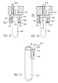
- a preferred embodiment of a contact-limiting element comprises a tiplet 170.
- tiplet 170 comprises a tubular body 179 having a peripheral flange 177, preferably extending radially with respect to said tubular body 179, and a thickened wall portion 178, adjacent the peripheral flange 177, having a generally larger diameter than a remaining portion of the tubular body 179 of the tiplet 170.
- An axially extending inner bore 180 passes through the tiplet 170.
- Bore 180 includes an outwardly flared end 181, which facilitates insertion of a bottom free end of a tubular element of a pipetting apparatus into the bore 180 of tiplet 170.
- the inner diameter of inner bore 180 provides an interference fit with the outer diameter of the tubular element to frictionally secure tiplet 170 onto the tubular element when the bottom end of the tubular element is forced into the inner bore 180.
- the tubular body 179 and inner bore 180 are generally cylindrical in shape, consistent with the typically cylindrical shape of the tubular element of a substance transfer device, such as a pipetting or aspirating device.
- the present invention is not limited, however, to contact-limiting. elements having tubular bodies and inner bores that are cylindrical, as the tubular body and inner bore of the contact-limiting element, may have a shape that is other than cylindrical to conform to non-cylindrical tubular elements of substance transfer devices.
- the bottom end of the tiplet 170 preferably includes a beveled portion 182.
- the beveled portion 182 will prevent a vacuum from forming between the end of the tiplet 170 and the bottom 163 of the receptacle 162.
- Tiplet 470 comprises a tubular body 479 having a peripheral flange 477, preferably extending radially with respect to said tubular body 479, and a thickened wall portion 478, adjacent the peripheral flange 477, of generally larger diameter than a remaining, portion of the tubular body 479 of the tiplet 470.
- An axially extending inner bore 480 passes through the tiplet 470.
- Bore 480 includes a bevelled end 481, which facilitates insertion of an upper end 483 of the tubular body 479 into a bottom free end of a tubular element 420.
- the outer diameter of upper end 483 of the tubular body 479 provides an interference fit with the inner diameter of the tubular element 420 to frictionally secure tiplet 470 onto the tubular element 420 when the upper end 483 of the tubular body 479 is inserted into the bottom free end of the tubular element 420.
- tubular body 479 and inner bore 480 need not necessarily be generally cylindrical in shape, as illustrated in FIGURE 17, may have a shape that is other than cylindrical to conform to non-cylindrical tubular elements of substance transfer devices.
- the bottom end of the tiplet 470 preferably includes a beveled portion 482.
- the beveled portion 482 will prevent a vacuum from forming between the end of the tiplet 470 and the bottom 163 of the receptacle 162.
- the reaction receptacle apparatus 160 preferably includes contact-limiting element holding structures in the form of tiplet holding structures 176 adjacent the open mouth 161 of each respective receptacle 162.
- Each tiplet holding structure 176 provides an elongated orifice 150, preferably generally cylindrical in shape, within which is received a contact-limiting tiplet 170 (470).
- An annular end face 152 extends about the orifice 150, and when the tiplet 170 (470) is inserted into a tiplet holding structure 176, the peripheral flange 177 (477) contacts the end face 152 of tiplet holding structure 176 to limit the depth to which the tiplet 170. (470) can be inserted into the orifice 150.
- the outside diameter of the thickened wall portion 178 (478) is slightly larger than inside diameter of the orifice 150.
- a plurality of small, raised ribs 154 extend longitudinally along the inner wall of the orifice 150 at different circumferentially-spaced positions.
- the crests of the raised ribs 154 define an inner diameter that is slightly smaller than the outer diameter of the thickened wall portion 178 (478). Accordingly, the tiplet holding structure 176 provides a sliding interference fit between the thickened wall portion 178 (478) and the inner diameter of the orifice 150 or between the thickened wall portion 178 (478) and the crests of the ribs 154.
- tiplet 170 (470) is held securely within the orifice 150 of the tiplet holding structure 176 so the tiplet 170 (470) is unlikely to dislodge from the tiplet holding Structure 176, even if the reaction receptacle apparatus 160 is inverted.
- the tiplet 170 (470) is frictionally engaged by the tubular element of a pipetting apparatus while the tiplet 170 (470) is held in the tiplet holding structure 176, the frictional hold between the tiplet 170 (470) and the tubular element is greater than the frictional hold between the tiplet 170 (470) and the tiplet holding structure 176.
- the tiplet 170 (470) should remain secured on the end of the tubular element-when the tubular element is withdrawn in an axial direction from the orifice 150 of the tiplet holding structure 176.
- tiplet 170 the embodiment shown in FIGURE 2.
- tiplet 470 the embodiment shown in FIGURE 17
- Reaction receptacle apparatus 60 includes a tiplet holding structure 76 that is different from the tiplet holding structure 176 of reaction receptacle apparatus 160 of FIGURE 1. In all other respects, however, reaction receptacle apparatus 60 is identical to reaction receptacle apparatus 160.
- Tiplet holding structure 76 includes a tiplet-receiving orifice 79 with an end face 77 surrounding orifice 79 and forming a partial annulus.
- a slot 78 extends. longitudinally along a wall of the tiplet holding structure 76. Slot 78 allows the tiplet holding structure 76 to expand when a tiplet 170 is inserted . into the tiplet holding structure 76, and the resiliency of the material of which the reaction receptacle apparatus 60 is formed provides a frictional fit between a tiplet 170 and the tiplet holding structure 76.
- connecting rib structure 164 extends along both sides of the reaction receptacle apparatus 160 and defines downwardly facing shoulders 165 with outer edges 192 along each side of the reaction receptacle apparatus 160 (60).
- the reaction receptacle apparatus 160 (60) is operatively supported within a diagnostic instrument or the like by means of the shoulders 165 resting on parallel, horizontal flanges spaced apart from one another by a distance slightly greater than the width of the individual receptacle 162, but less than the width of the rib structure 164 between edges 192.
- Such flanges may be defined by a slot extending from an edge of a reaction receptacle apparatus supporting plate.
- the reaction receptacle apparatus may be inserted into and removed from a supporting structure by a reaction receptacle apparatus manipulating device.
- two upwardly angled portions 82 provide upwardly angled shoulders 84 on both sides of the reaction receptacle apparatus 160 (60).
- the upwardly angled shoulders 84 facilitate sliding of the reaction receptacle apparatus 160 (60) onto a supporting structure.
- FIGURES 9 and 10 An exemplary device 20 for manipulating a reaction receptacle apparatus 160 (60) is shown in FIGURES 9 and 10.
- the device 20 includes a base structure 22 attached to a mounting bracket or mounting plate of an instrument which processes the contents of numerous reaction receptacle apparatuses according to the present invention and may perform one or more assays within each reaction receptacle apparatus 160.
- the manipulating device 20 moves the reaction receptacle apparatuses from one location to another within the instrument.
- the manipulating device 20 further includes a rotating transport carrier 28 which rotates about a shaft 25 by means of a stepper motor 24 which turns a pulley 29 attached to the shaft 25 via a drive belt 27.
- the shaft 25 and pulley 29 may be covered by a pulley .housing 26.
- the rotating transport carrier 28 includes a base plate 30 covered by a housing 32.
- the housing 32 includes an opening 36 at one end thereof, and the base plate 30 includes a slot 31 formed therein.
- a manipulating hook 34 is mounted for sliding translation in the slot 31 and is attached to a threaded drive screw 40 that is actuated by a stepper motor 38 to extend and retract the manipulating hook 34 within the slot 31.
- the manipulating hook 34 is extended to a forward position projecting from the opening 36 as shown in FIGURE 9.
- a lateral translation of the manipulating hook 34 is effected, such as by effecting a small rotation of the rotating transport carrier 28, to place the manipulating hook 34 in the space 50 between the lower portion 173 of the arcuate shield structure 185 and the transverse piece 167 of the receptacle apparatus manipulating structure 166.
- the stepper motor 38 retracts the drive screw 40, pulling the manipulating hook 34 and the reaction receptacle apparatus 160 back into the rotating transport carrier 28.
- the downwardly facing shoulders 165 defined by the connecting rib structure 164 of the reaction receptacle apparatus 160 are supported by the base plate 30 along opposite edges 42 of the slot 31, thus supporting the reaction receptacle apparatus 160 in the rotating transport carrier 28.
- the carrier 28 With the reaction receptacle apparatus 160 secured within the rotating transport carrier 28, the carrier 28 can be rotated by the stepper motor 24 to a different position at which the stepper motor 38 can extend the drive screw 40 and the manipulating hook 34 to push the reaction receptacle apparatus 160 out of the rotating transport carrier 28 and into a different location within the instrument.
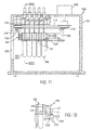
- FIGURE 11 An exemplary reaction receptacle processing device 200 is shown in FIGURE 11.
- Processing device. 200 may represent one of many similar or related devices which together make up a reaction receptacle processing instrument.
- the processing device 200 includes a housing 201 with an opening 202 formed therein.
- a reaction receptacle apparatus 160 can be inserted into the processing device 200. through the opening 202 and removed through the opening 202 by a manipulating device such as the manipulating device 20 shown in FIGURES 9 and 10 and described above.
- a manipulating device such as the manipulating device 20 shown in FIGURES 9 and 10 and described above.
- Inside the housing 201 the reaction receptacle apparatus is supported by a receptacle carrier structure 206 having a base plate 204 (see also FIGURES 13 and 14) with a receptacle receiving slot (not shown) formed therein so that the reaction receptacle apparatus 160 can be supported by means of portions of the plate 204 along opposite edges of the slot supporting the connecting rib structure 164 of the reaction receptacle apparatus 160.
- Processing device 200 may be a mixing device for mixing the contents of the reaction receptacle apparatus 160; the processing device 200 may be a dispensing device for simultaneously dispensing substance into each of the individual receptacles 162 of the reaction receptacle apparatus 160; or the processing device 200 may be a device for simultaneously aspirating substance from each of the receptacles 162 of the reaction receptacle apparatus 160. Alternatively, the processing device 200 may perform any combination of two or more of the above functions.
- the receptacle carrier structure 206 may be coupled to an orbital mixing assembly comprising a stepper motor 208, a drive wheel 210 with an eccentric pin 212 extending therefrom, and an idler wheel 216 having an eccentric pin.218 and being coupled to the drive wheel 210 by means of a belt 214.
- the stepper motor 208 rotates the drive pulley 210 which in turn rotates the idler pulley 216
- the eccentric pins 212 and 218 engage the receptacle carrier structure 206 thus moving the receptacle carrier structure and the reaction receptacle apparatus 160 carried thereby in an orbital path of motion. Movement at a sufficiently high frequency can cause sufficient agitation of the reaction receptacle apparatus 160 to mix the contents thereof.
- lateral ribs 190 extend longitudinally along the outer walls of the receptacles 162 above the connecting rib structure 164 at diametrically opposed positions with respect to one another.
- the outer edges of the lateral ribs 190 are generally co-planar with the outer edges 192 of the connecting rib structure 164.
- the lateral ribs provide additional strength and rigidity to the open mouth 161 of the receptacle 162.
- the outer edges of the lateral ribs 190 can engage the sidewalls of a receptacle carrier structure 206, as shown in FIGURES 13 and 14, to limit the extent to which the reaction receptacle apparatus 160 will be allowed to tilt laterally within the receptacle carrier structure 206.
- lateral ribs 190 be provided on each of the receptacles 162, lateral ribs 190, when included, can be provided on less than all of the receptacles 162 as well.
- the reaction receptacle apparatus 160 can be engaged by a dispensing and/or aspirating system comprising an array of tubular elements 220.
- the dispensing and/or aspirating system preferably includes five tubular elements 220 oriented so as to correspond to the orientations of the individual receptacles 162 of the reaction receptacle apparatus 160.
- the tubular elements 220 are coupled to means for providing vertical movement of the free ends of the tubular elements 220 with respect to the reaction receptacle apparatus 160 to move the ends of the tubular elements 220 into and out of the individual receptacles 162 to aspirate and/or dispense substances.
- tubular elements 220 are coupled to means, such as a fluid pump and fluid source or a vacuum pump, for delivering fluid to each of the tubular elements 220 or providing a suction at each of the tubular elements 220.
- tubular elements 220 are inserted into the reaction receptacles 162 before the tubular elements 220 are inserted into the reaction receptacles 162, it is preferred that a contact-limiting tiplet 170 be placed on the end of each tubular element 220. Accordingly, the tubular elements 220 are first lowered to simultaneously engage all of the tiplets 170 carried in their respective tiplet holding structures 176.
- the array of tubular elements 220 can be coupled to means for providing lateral translation of the tubular elements 220 for moving the tubular elements 220 to a position above the tiplet holding structures 176.
- the receptacle carrier structure 206 itself can be moved laterally to place the tiplet holding structures 176 below the respective tubular elements 220.
- the stepper motor 208 can move the assembly a limited number of steps, thus moving the receptacle carrier structure 206 and the reaction receptacle apparatus 160 a portion of one orbital path to place the tiplet holding structures 176 below the tubular elements 220 as shown in FIGURE 13.
- each of the respective tiplet holding structures 176 (76) is preferably disposed at a position between adjacent receptacles 162. Locating the tiplet holding structures 176 (76) between the adjacent receptacles 162 places the tubular elements 220 on the orbital paths of the contact-limiting element holding structures 176 (76) as the reaction receptacle apparatus 160 is moved with respect to the pipettes 220. Thus, the orbital mixer assembly can be used to properly position the tiplet holding structures 176 (76) with respect to the tubular elements 220, as described above.
- placing the tiplet holding structures 176 (76) between adjacent receptacles 162 provides for a narrower profile of the reaction receptacle apparatus 160 (60) than if the tiplet holding structures 176 (76) were located on the outer portion of the receptacles 162 nearest the edge 192 of the connecting rib structure 164.
- the processing device 200 may also include an array of fixed nozzles 222 for dispensing substances into the receptacles 162 of the reaction receptacle apparatus 160 held in the receptacle carrier structure 206.
- an alternate, oscillating mixing device 230 comprises a skewed wobbler plate 232 disposed on a shaft 234 driven by a motor (not shown).
- the reaction receptacle apparatus 160 carried by a carrier structure (not shown), is moved with respect to the oscillating mixing device 230 -- or the oscillating mixing 230 is moved with respect to the reaction receptacle apparatus 160 -- until the wobbler plate 232 is disposed in the space 50 between the lower portion 173 of the arcuate shield structure 185 and the transverse piece 167 of the receptacle apparatus manipulating structure 166.
- the shaft 234 rotates, the position of the portion of the wobbler plate 232 engaged with the receptacle apparatus 160 varies in a linearly oscillating manner to impart a linear oscillating motion to the reaction receptacle apparatus 160.
- the raised ridges 171, 172 provided in the middle of the convex surfaces of the transverse piece 167 and the lower portion 173, respectively, can minimize the surface contact between the wobbler plate 232 and the convex surfaces, thus limiting friction therebetween. It has been determined, however, that raised ridges 171, 172 can interfere with the engagement of the manipulating hook 34 of a manipulating device 20 with the apparatus manipulating structure 166. Therefore, raised ridges 171, 172 are preferably omitted.
- a linear array of individual receptacles 162 are integrally coupled together by the connecting rib structure 164.
- reaction receptacle apparatus 360 includes a plurality of individual receptacles 362, each having an open receptacle mouth 361.
- the reaction receptacle apparatus 360 includes five individual receptacles 362.
- Individual receptacles 362 are connected to one another by a connecting rib structure 364.
- Reaction receptacle apparatus.360 is in most respects identical to the reaction receptacle apparatuses described above and shown in Figures 1, 4, and 5, except that reaction receptacle apparatus 360 does not include contact-limiting holding structures 176 (76) associated with each individual receptacle 362. Nor does reaction receptacle apparatus 360 include a contact-limiting element, such as tiplet 170, associated with each individual receptacle 362.
- Reaction receptacle apparatus 360 can also include a label-receiving structure 374 having an upper portion 377 and a lower portion 375 cooperating so as to define a flat label-receiving surface 376.
- a vertical gusset wall 378 extends between the upper portion 377 of label-receiving structure 374 and the outer wall of the endmost individual receptacle 362.
- reaction receptacle apparatus 360 includes an arcuate shield structure 385 having an upper portion 369 and a lower portion 373.
- a receptacle apparatus manipulating structure 366 includes a transverse piece 367 connected to the arcuate shield structure 385 by means of a plate 368 extending between upper portion 369 of arcuate shield structure 385 and transverse piece 367, and a gusset wall 383 extending between the lower portion 373 of the arcuate shield structure 385 and the transverse piece 367 of the receptacle apparatus manipulating structure 366.
- the transverse piece 367 and the lower portion 373 of the arcuate shield structure 385 may have mutually-facing convex surfaces, and the surfaces may include vertical arcuate ridges 371 and 372, respectively.
- the receptacle apparatus manipulating structure 366 and the arcuate ridges 371 and 372 of the reaction receptacle apparatus 360 serve the same function as the receptacle apparatus manipulating structure 166 and the raised arcuate ribs 171 and 172 described above.
- the reaction receptacle apparatus 360 may further include connecting walls 380 extending between adjacent individual receptacles 362 at upper portions thereof above the connecting rib structure 364.
- a gusset wall 382 may be provided between the endmost individual receptacle 362 and the arcuate shield structure 385.
- the reaction receptacle apparatus 360 may further include lateral ribs 390 extending vertically along the outer surfaces of diametrically opposed positions of upper portions of the individual receptacles 362.
- the lateral ridges 390 of the reaction receptacle apparatus 360 serve the same function as do the lateral ribs 190 described above.
Claims (27)
- Eine Behältnisvorrichtung (60, 160) zur Verwendung bei der Durchführung von chemischen oder biologischen Tests, die aufweist:wobei jede der Haltestrukturen (76, 176) für Kontakt beschränkende Elemente mit einem der Kontakt beschränkenden Elemente (170, 470) verbunden ist, und(a) eine Vielzahl von Behältnissen (162) zum Enthalten einer oder mehrerer Stoffe, wobei die Behältnis (162) operativ miteinander verbunden sind und in der Lage sind, mit einer Stoffüberführungsvorrichtung zu interagieren, die gestaltet und eingerichtet ist, um Stoffe in die Behältnisse (162) hinein abzugeben oder aus diesen zu entnehmen;(b) eines oder mehrere Kontakt beschränkende Elemente (170, 470), wobei jedes Kontakt beschränkendes Element (170, 470) mit einem oder mehreren dieser Behältnisse (162) verbunden ist, wobei die Kontakt beschränkenden Elemente (170, 470) gestaltet und eingerichtet sind, um operativ im Eingriff mit der Stoffüberführungsvorrichtung zu stehen, um den Kontakt zwischen der Stoffüberführungsvorrichtung und Stoffen, die in eines oder mehrere der Behältnisse (162) hinein abgegeben oder aus diesen entnommen werden, durch die Stoffüberführungsvorrichtung zu beschränken; und(c) eine oder mehrere Haltestrukturen (76, 176) für Kontakt beschränkende Elemente, wobei jede Haltestruktur (76, 176) für Kontakt beschränkende Elemente mit zumindest einem der Behältnisse (162) verbunden ist und an die äußere Oberfläche oder Oberflächen davon angebracht ist,
wobei jede Haltestruktur (76, 176) für Kontakt beschränkende Elemente gestaltet und eingerichtet ist, um:(i) das verbundene Kontakt beschränkende Elemente (170, 470) in einer operativen Orientierung in Nachbarschaft zu den einen oder mehreren verbundenen Behältnissen (162) zu empfangen und entfernbar zu halten, um es dem Kontakt beschränkenden Element (170, 470) zu ermöglichen, operativ im Eingriff durch die Stoffüberführungsvorrichtung zu stehen, und(ii) es dem verbundenen Kontakt beschränkenden Element (170, 470) zu ermöglichen, von der verbundenen Haltestruktur (76, 176) für das Kontakt beschränkende Element entfernt zu werden, wenn das verbundene Kontakt beschränkende Element (170, 470) operativ im Eingriff durch die Stoffübertragungsvorrichtung steht. - Die Behältnisvorrichtung (60, 160) nach Anspruch 1, wobei zwei oder mehrere der Behältnisse (162) so angeordnet sind, um gleichzeitig im Eingriff durch die Stoffübertragungsvorrichtung stehen zu können, um es der Stoffübertragungsvorrichtung zu ermöglichen, Stoffe in jedes der zwei oder mehreren Behältnisse (162) simultan hinein abzugeben oder daraus zu entfernen.
- Behältnisvorrichtung (60, 160) nach Anspruch 1 oder 2, wobei die Behältnisse (162) fest miteinander verbunden sind.
- Behältnisvorrichtung (60, 160) nach einem der Ansprüche 1-3, die fünf der Behältnisse (162) aufweist.
- Behältnisvorrichtung (60, 160) nach Anspruch 3 oder 4, die ferner eine Behältnisse verbindende Struktur (164) aufweist, die die Behältnisse (162) fest miteinander verbindet.
- Behältnisvorrichtung (60, 160) nach Anspruch 5, wobei die Behältnisse (162) in einer Reihe von der Länge nach beabstandeten Behältnissen (162) angeordnet sind.
- Behältnisvorrichtung (60, 160) nach Anspruch 6, wobei die Behältnisse verbindende Struktur (164) mit äußeren Oberflächen der Behältnisse (162) verbunden ist, wobei sich die Behältnisse verbindende Struktur (164) von den äußeren Oberflächen hinweg und entlang der Reihe von Behältnissen (162) erstreckt und im wesentlichen geradkantige Oberflächen (192) definiert, die sich entlang einander gegenüberliegenden Seiten der Reihe von Behältnissen (162) und im wesentlichen ebene Randleisten (165) erstreckt, die zu den unteren Enden (163) der Behältnisse (162) entgegentreten.
- Behältnisvorrichtung (60, 160) nach Anspruch 7, wobei ein Ende der Behältnisse verbindenden Struktur (164) aufwärts entlang sich einander gegenüberliegenden Seiten der Reihe von Behältnissen (162) gebogen ist, um aufwärts abgeschrägte Randoberflächen (84) zu definieren, die sich von den im wesentlichen geradkantigen Oberflächen (192) weg erstrecken.
- Behältnisvorrichtung (60, 160) nach einem der Ansprüche 1-8, die ferner eine Handhabungsstruktur (166) für die Behältnisvorrichtung aufweist, die mit den Behältnissen (162) verbunden ist, wobei diese Handhabungsstruktur (166) für die Behältnisvorrichtung gestaltet und eingerichtet ist, um im Eingriff durch eine Behältnisvorrichtung handhabende Vorrichtung zu stehen, um die Behältnisvorrichtung (60, 160) zu handhaben.
- Behältnisvorrichtung (60, 160) nach einem der Ansprüche 1-9, die ferner eine eine Markierung aufnehmende Struktur (174) aufweist, die mit den Behältnissen (162) verbunden ist, und eine eine Markierung aufnehmenden Oberfläche (175) darbietet, um von Menschen und/oder maschinenlesbare Information daran anzubringen.
- Behältnisvorrichtung (60, 160) nach einem der Ansprüche 7-10, wobei zumindest eines der Behältnisse (162) Rippen besitzt, die sich nach außen von sich einander gegenüberliegenden äußeren Oberflächen davon erstrecken, wobei die sich gegenüberliegenden äußeren Oberflächen den sich einander gegenüberliegenden Seiten der Reihe von Behältnissen (162) entsprechen.
- Behältnisvorrichtung (60, 160) nach einem der Ansprüche 5-11, wobei die Behältnisse (162) und die Behältnis verbindende Struktur (164) einstückig ausgebildet sind.
- Behältnisvorrichtung (60, 160) nach einem der Ansprüche 1-12, wobei jedes der Behältnisse (162) eine im wesentlichen zylindrische Hohlstruktur mit einem kreisförmigen oberen Ende (161) und einem geschlossenen unteren Ende (163) beinhaltet.
- Behältnisvorrichtung (60, 160) nach einem der Ansprüche 1-13, wobei jedes des einen oder mehreren Kontakt beschränkenden Elemente (170, 174) aufweist:wobei das Kontakt beschränkende Element (170, 470) gestaltet und eingerichtet ist, um durch Reibung auf einem freien Ende eines röhrenförmigen Elementes der Stoffüberführungsvorrichtung befestigt zu sein, wenn das Kontakt beschränkende Element (170, 470) im Eingriff durch das röhrenförmige Element steht.einen röhrenförmigen Körper (179, 479) mit einem proximalen Ende und einem distalen Ende und einer inneren Bohrung (180, 480), die in dem röhrenförmigen Körper (179, 479) von dem proximalen Ende zum distalen Ende ausgebildet ist; undeinen äußeren Flansch (177, 477) der über einem äußeren Rand des röhrenförmigen Körpers (179, 479) angebracht ist,
- Behältnisvorrichtung (60, 160) nach Anspruch 14, wobei ein Teil der inneren Bohrung (180) so bemessen ist, um das freie Ende des röhrenförmigen Elementes, das in die innere Bohrung (180) eingeführt wird, aufzunehmen, und um einen Presssitz zwischen einer Innenfläche des röhrenförmigen Körpers (179) und einer äußeren Oberfläche des freien Endes des röhrenförmigen Elementes des röhrenförmigen Elements bereitzustellen, wenn das röhrenförmige Element in die innere Bohrung eingeführt wird.
- Behältnisvorrichtung (60, 160) nach Anspruch 14, wobei der röhrenförmige Körper (479) so bemessen ist, um in das freie Ende des röhrenförmigen Elements eingeführt zu werden, und um einen Presssitz zwischen einer äußeren Oberfläche des röhrenförmigen Körpers (479) und einer Innenfläche des freien Endes des röhrenförmigen Elementes bereitzustellen, wenn der röhrenförmige Körper (479) in das röhrenförmige Element eingeführt wird.
- Behältnisvorrichtung (60, 160) nach einem der Ansprüche 14-16, wobei der röhrenförmige Körper (179, 479) und die innere Bohrung (180, 480) des Kontakt beschränkenden Elementes (170, 470) eine im wesentliche zylindrische Form besitzen.
- Behältnisvorrichtung (60, 160) nach einem der Ansprüche 14-17, wobei das distale Ende des röhrenförmigen Körpers (179, 479) einen abgeschrägten Bereich (182, 482) aufweist.
- Behältnisvorrichtung (60, 160) nach einem der Ansprüche 14-18, wobei das Kontakt beschränkende Element (170, 470) ferner eine Struktur (178, 478) aufweist, die sich für eine Längsausdehnung entlang des röhrenförmigen Körpers (179, 479) von dem äußeren Flansch (177, 477) erstreckt und einen Außendurchmesser definiert, der größer ist als ein Außendurchmesser eines verbleibenden Bereiches des röhrenförmigen Körpers (179, 479).
- Behältnisvorrichtung (60, 160) nach einem der Ansprüche 14-19, wobei jede der einen oder mehreren Haltestrukturen (76, 176) für Kontakt beschränkende Elemente eine verlängerte Öffnung (79, 150) besitzt, die darin ausgebildet sind, um den röhrenförmigen Körper (179, 479) einen verbundenen Kontakt beschränkenden Elementes (170, 470) aufzunehmen, das in die verlängerte Öffnung (79, 150) eingeführt wird, und eine äußere Endfläche (77, 152), die quer zu einer Achse der verlängerten Öffnung (79, 150) orientiert ist, und ein Ende der verlängerten Öffnung (79, 150) umgibt, wobei der äußere Flansch (177, 477) des Kontakt beschränkenden Elementes (170, 470) im Kontakt steht mit der äußeren Endfläche (77, 152) der Haltestruktur (76, 176) für Kontakt beschränkende Elemente, wenn der röhrenförmige Körper (179, 479) des Kontakt beschränkenden Elementes (170, 470) vollständig in die verlängerte Öffnung (79, 150) eingeführt ist, wobei die Haltestruktur (76, 176) für Kontakt beschränkende Elemente gestaltet und eingerichtet ist, um einen Rutschpresssitz zwischen der verlängerten Öffnung (79, 150) und dem röhrenförmigen Körper (179, 479) des verbundenen Kontakt beschränkenden Elementes (170, 470) bereitzustellen, das in die verlängerte Öffnung (79, 150) eingeführt ist, wobei das Kontakt beschränkende Element (170, 470) durch Reibung innerhalb der verlängerten Öffnung (79, 150) befestigt ist.
- Behältnisvorrichtung (60) nach Anspruch 20, die ferner eine Rille (78) aufweist, die in der Haltestruktur (76) für Kontakt beschränkende Elemente ausgebildet ist, und sich entlang einer Seite der verlängerten Öffnung (79) erstreckt, wobei die Rille (78) so gestaltet und eingerichtet ist, um es der Haltestruktur (76) für Kontakt beschränkende Elemente zu ermöglichen, sich elastisch auszudehnen, wenn das Kontakt beschränkende Element (170, 470) in die verlängerte Öffnung (79) eingeführt wird.
- Behältnisvorrichtung (160) nach Anspruch 20, wobei der röhrenförmige Körper (179, 479) und die innere Bohrung (180, 480) des Kontakt beschränkenden Elementes (170, 470) eine im wesentlichen zylindrische Form aufweisen und die verlängerte Öffnung (150) einer im wesentlichen zylindrische Form aufweist, und wobei die Haltestruktur (176) für Kontakt beschränkende Elemente ferner eine Vielzahl von im Umfang beabstandeter axial sich axial erstreckender erhöhter Rippen (154) aufweist, die auf einer inneren Oberfläche der verlängerten Öffnung (150) ausgebildet sind, wobei ein Innendurchmesser, der durch Oberteile der Vielzahl von erhöhten Rippen (154) definiert wird, kleiner ist als ein Außendurchmesser eines Teils des röhrenförmigen Körpers (179, 479) des verbundenen Kontakt beschränkenden Elementes (170, 470), das in die verlängerte Öffnung (150) eingeführt wird, um den Rutschpresssitz zwischen den Oberteilen der Vielzahl von erhöhten Rippen (154) und dem röhrenförmigen Körper (179, 479) des verbundenen Kontakt beschränkenden Elementes (170, 470) bereit zu stellen.
- Behältnisvorrichtung (160) nach Anspruch 22, wobei der röhrenförmige Körper (179, 479) des Kontakt beschränkenden Elementes (170, 470) einen verdickten Wandbereich (178, 478) entlang einer Ausdehnung des röhrenförmigen Körpers (179, 479) aufweist, wobei der verdickte Wandbereich (178, 478) einen Außendurchmesser besitzt, der größer ist als ein Außendurchmesser eines verbleibenden Bereichs des röhrenförmigen Körpers (179, 479), und wobei der Innendurchmesser, der durch die Oberteile der Vielzahl von erhöhten Rippen (154) definiert wird, kleiner ist als der Außendurchmesser des verdickten Wandbereiches (178, 478) des röhrenförmigen Körpers (179, 479) des verbundenen Kontakt beschränkenden Elementes (170, 470), das in die verlängerte Öffnung (150) eingeführt wird, um den Rutschpresssitz zwischen den Oberteilen der Vielzahl von erhöhten Rippen (154) und des verdickten Wandbereichs (178, 478) des röhrenförmigen Körpers (179, 479) des verbundenen Kontakt beschränkenden Elementes (170, 470) bereitzustellen.
- Behältnisvorrichtung (60, 160) nach einem der Ansprüche 1-23, die ferner eine Schildstruktur (185) aufweist, die an einem Ende der Behältnisvorrichtung (60, 160) angeordnet ist und eine Behältnisvorrichtung handhabende Struktur (166), die an die Schildstruktur (185) angebracht ist, wobei die die Behältnisvorrichtung handhabende Struktur (166) eine seitliche Platte (168) aufweist, die sich von der Schildstruktur (185) erstreckt, und ein Querstück (167), das an einem Ende der seitlichen Platte (168) angebracht ist, gegenüberliegend zu der Schildstruktur (185), und sich darauf bezogen transversal erstreckt, wobei die die Behältnisvorrichtung handhabende Struktur (166) so gestaltet und eingerichtet ist, dass sie dadurch im Eingriff durch eine Behältnisvorrichtungs handhabende Vorrichtung steht, dass ein Handhabungshaken der Behältnisvorrichtung handhabenden Vorrichtung in einen Raum (50) zwischen der Schildstruktur (185) und dem transversalen Stück (167) angebracht wird, um die Behältnisvorrichtung (60, 160) zu handhaben.
- Behältnisvorrichtung (60, 160) nach Anspruch 24, wobei die Schildstruktur (185) und das transversale Stück (167) beiderseitig sich gegenüberliegende konvexe Oberflächen auf sich einander gegenüberliegenden Seiten des Raumes (50) zwischen der Schildstruktur (185) und dem transversalen (167) aufweisen.
- Behältnisvorrichtung (60, 160) nach Anspruch 25, die ferner erhöhte Leisten (171, 172) aufweist, wobei eine der Leisten (171, 172) auf jeder der beiderseitig sich gegenüberliegenden konvexen Oberflächen angebracht ist, und wobei jede der erhöhten Leisten (171, 172) sich axial, bezogen auf eine Krümmung von jeder der konvexen Oberfläche erstreckt, und im wesentlichen in der Mitte der konvexen Oberfläche angeordnet ist.
- Behältnisvorrichtung (60, 160) nach einem der Ansprüche 1-26, wobei jedes der Behältnisse (162) zumindest eine der Haltestrukturen (76, 176) für ein Kontakt beschränkendes Element daran angebracht aufweist.
Priority Applications (1)
| Application Number | Priority Date | Filing Date | Title |
|---|---|---|---|
| EP02002408A EP1216754B1 (de) | 1997-05-02 | 1998-05-01 | Reaktion Behälter Apparat |
Applications Claiming Priority (3)
| Application Number | Priority Date | Filing Date | Title |
|---|---|---|---|
| US4680097P | 1997-05-02 | 1997-05-02 | |
| US46800P | 1997-05-02 | ||
| PCT/US1998/008586 WO1998050158A1 (en) | 1997-05-02 | 1998-05-01 | Reaction receptacle apparatus |
Related Child Applications (1)
| Application Number | Title | Priority Date | Filing Date |
|---|---|---|---|
| EP02002408A Division EP1216754B1 (de) | 1997-05-02 | 1998-05-01 | Reaktion Behälter Apparat |
Publications (2)
| Publication Number | Publication Date |
|---|---|
| EP0979146A1 EP0979146A1 (de) | 2000-02-16 |
| EP0979146B1 true EP0979146B1 (de) | 2002-09-25 |
Family
ID=21945462
Family Applications (1)
| Application Number | Title | Priority Date | Filing Date |
|---|---|---|---|
| EP98919968A Expired - Lifetime EP0979146B1 (de) | 1997-05-02 | 1998-05-01 | Reaktion behälter apparat |
Country Status (11)
| Country | Link |
|---|---|
| US (3) | US6086827A (de) |
| EP (1) | EP0979146B1 (de) |
| JP (3) | JP2001524214A (de) |
| KR (1) | KR20010012479A (de) |
| AT (2) | ATE282473T1 (de) |
| AU (1) | AU735267B2 (de) |
| CA (1) | CA2287962C (de) |
| DE (2) | DE69827678T2 (de) |
| DK (2) | DK1216754T3 (de) |
| ES (2) | ES2231589T3 (de) |
| WO (1) | WO1998050158A1 (de) |
Families Citing this family (109)
| Publication number | Priority date | Publication date | Assignee | Title |
|---|---|---|---|---|
| US6048734A (en) | 1995-09-15 | 2000-04-11 | The Regents Of The University Of Michigan | Thermal microvalves in a fluid flow method |
| AU735267B2 (en) * | 1997-05-02 | 2001-07-05 | Gen-Probe Incorporated | Reaction receptacle apparatus |
| US6415669B1 (en) * | 1998-04-09 | 2002-07-09 | Ccs Packard, Inc. | Dispensing apparatus having means for loading pipette tips in a dispense head |
| ES2322859T3 (es) * | 1998-05-01 | 2009-06-30 | Gen-Probe Incorporated | Analizador de diagnostico automatizado. |
| AU2006230729B2 (en) * | 1998-05-01 | 2008-04-03 | Gen-Probe Incorporated | Transport mechanism |
| US8337753B2 (en) | 1998-05-01 | 2012-12-25 | Gen-Probe Incorporated | Temperature-controlled incubator having a receptacle mixing mechanism |
| JP2000046841A (ja) * | 1998-07-31 | 2000-02-18 | Tosoh Corp | 自動測定装置 |
| WO2001028680A2 (en) * | 1999-10-20 | 2001-04-26 | Gentra Systems, Inc. | Mixing and pouring apparatus with rotatable arm and related vessel |
| US6846293B2 (en) * | 2000-12-05 | 2005-01-25 | Bradley S. Butler | Spinal fluid collection system |
| US6692700B2 (en) | 2001-02-14 | 2004-02-17 | Handylab, Inc. | Heat-reduction methods and systems related to microfluidic devices |
| CA2643398C (en) | 2001-03-09 | 2010-04-27 | Gen-Probe Incorporated | Penetrable cap |
| US7323140B2 (en) * | 2001-03-28 | 2008-01-29 | Handylab, Inc. | Moving microdroplets in a microfluidic device |
| US8895311B1 (en) | 2001-03-28 | 2014-11-25 | Handylab, Inc. | Methods and systems for control of general purpose microfluidic devices |
| US7829025B2 (en) | 2001-03-28 | 2010-11-09 | Venture Lending & Leasing Iv, Inc. | Systems and methods for thermal actuation of microfluidic devices |
| US7010391B2 (en) | 2001-03-28 | 2006-03-07 | Handylab, Inc. | Methods and systems for control of microfluidic devices |
| US6852287B2 (en) | 2001-09-12 | 2005-02-08 | Handylab, Inc. | Microfluidic devices having a reduced number of input and output connections |
| US7488303B1 (en) * | 2002-09-21 | 2009-02-10 | Glaukos Corporation | Ocular implant with anchor and multiple openings |
| US6626051B2 (en) * | 2001-08-14 | 2003-09-30 | Investigen Biotechnologies, Inc. | Lid for sample holder |
| US6752967B2 (en) * | 2002-01-04 | 2004-06-22 | Dade Behring Inc. | Stackable aliquot vessel array |
| DE10207847A1 (de) * | 2002-02-15 | 2003-08-28 | Zeiss Carl Jena Gmbh | Ausschiebeeinrichtung für einen Klimaschrank, insbesondere zur Aufnahme von Mikrotiterplatten (MTP) |
| AU2003226075B2 (en) * | 2002-04-12 | 2008-09-25 | Instrumentation Laboratory Company | Immunoassay probe |
| US7211224B2 (en) * | 2002-05-23 | 2007-05-01 | Millipore Corporation | One piece filtration plate |
| US6808304B2 (en) * | 2002-08-27 | 2004-10-26 | Dade Behring Inc. | Method for mixing liquid samples using a linear oscillation stroke |
| WO2004067162A2 (en) * | 2003-01-30 | 2004-08-12 | Ciphergen Biosystems Inc. | Apparatus for microfluidic processing and reading of biochip arrays |
| EP1443330A1 (de) * | 2003-02-03 | 2004-08-04 | Gilson Sas | Verfahren, Rack und Vorrichtung zur Vorbereitung von Proben für analytische Zwecke |
| WO2005011867A2 (en) | 2003-07-31 | 2005-02-10 | Handylab, Inc. | Processing particle-containing samples |
| ITMI20040743A1 (it) * | 2004-04-15 | 2004-07-15 | Cs Automazione S R L | Sistema di stoccaggio omogeneizzazione e dosaggio |
| CA2994321C (en) * | 2004-05-03 | 2023-08-08 | Handylab, Inc. | A microfluidic device and methods for processing polynucleotide-containing samples |
| US8852862B2 (en) | 2004-05-03 | 2014-10-07 | Handylab, Inc. | Method for processing polynucleotide-containing samples |
| US8211386B2 (en) * | 2004-06-08 | 2012-07-03 | Biokit, S.A. | Tapered cuvette and method of collecting magnetic particles |
| US20060018802A1 (en) * | 2004-07-09 | 2006-01-26 | Greenway Roger B Jr | Method and apparatus for reconfiguring a labware storage system |
| EP1909108B1 (de) | 2005-03-10 | 2019-05-29 | Gen-Probe Incorporated | Systeme und Verfahren zur Durchführung von Tests zum Nachweis oder zur Quantifizierung von Analyten |
| EP2333561A3 (de) | 2005-03-10 | 2014-06-11 | Gen-Probe Incorporated | System zum Durchführen von Tests in mehreren Formaten |
| US20090129987A1 (en) * | 2005-05-17 | 2009-05-21 | Wako Pure Chemical Industries, Ltd. | Connected Reagent Container |
| WO2007044917A2 (en) * | 2005-10-11 | 2007-04-19 | Handylab, Inc. | Polynucleotide sample preparation device |
| GB0521851D0 (en) * | 2005-10-26 | 2005-12-07 | Genial Genetic Solutions Ltd | Biological apparatus |
| JP4548359B2 (ja) * | 2006-02-20 | 2010-09-22 | 株式会社島津製作所 | 反応キット処理装置 |
| US7998708B2 (en) | 2006-03-24 | 2011-08-16 | Handylab, Inc. | Microfluidic system for amplifying and detecting polynucleotides in parallel |
| DK3088083T3 (en) | 2006-03-24 | 2018-11-26 | Handylab Inc | Method of carrying out PCR down a multi-track cartridge |
| US10900066B2 (en) | 2006-03-24 | 2021-01-26 | Handylab, Inc. | Microfluidic system for amplifying and detecting polynucleotides in parallel |
| US8088616B2 (en) | 2006-03-24 | 2012-01-03 | Handylab, Inc. | Heater unit for microfluidic diagnostic system |
| US8883490B2 (en) | 2006-03-24 | 2014-11-11 | Handylab, Inc. | Fluorescence detector for microfluidic diagnostic system |
| US11806718B2 (en) | 2006-03-24 | 2023-11-07 | Handylab, Inc. | Fluorescence detector for microfluidic diagnostic system |
| EP2091647A2 (de) | 2006-11-14 | 2009-08-26 | Handylab, Inc. | Mikrofluidisches system für parallele amplifikation und erkennung von polynukleotiden |
| US8387811B2 (en) * | 2007-04-16 | 2013-03-05 | Bd Diagnostics | Pierceable cap having piercing extensions |
| US8387810B2 (en) * | 2007-04-16 | 2013-03-05 | Becton, Dickinson And Company | Pierceable cap having piercing extensions for a sample container |
| US9186677B2 (en) * | 2007-07-13 | 2015-11-17 | Handylab, Inc. | Integrated apparatus for performing nucleic acid extraction and diagnostic testing on multiple biological samples |
| US8287820B2 (en) | 2007-07-13 | 2012-10-16 | Handylab, Inc. | Automated pipetting apparatus having a combined liquid pump and pipette head system |
| USD621060S1 (en) | 2008-07-14 | 2010-08-03 | Handylab, Inc. | Microfluidic cartridge |
| US8133671B2 (en) * | 2007-07-13 | 2012-03-13 | Handylab, Inc. | Integrated apparatus for performing nucleic acid extraction and diagnostic testing on multiple biological samples |
| US8105783B2 (en) | 2007-07-13 | 2012-01-31 | Handylab, Inc. | Microfluidic cartridge |
| US9618139B2 (en) | 2007-07-13 | 2017-04-11 | Handylab, Inc. | Integrated heater and magnetic separator |
| US8324372B2 (en) | 2007-07-13 | 2012-12-04 | Handylab, Inc. | Polynucleotide capture materials, and methods of using same |
| US8182763B2 (en) | 2007-07-13 | 2012-05-22 | Handylab, Inc. | Rack for sample tubes and reagent holders |
| US20090136385A1 (en) * | 2007-07-13 | 2009-05-28 | Handylab, Inc. | Reagent Tube |
| USD618820S1 (en) | 2008-07-11 | 2010-06-29 | Handylab, Inc. | Reagent holder |
| US20100009351A1 (en) * | 2008-07-11 | 2010-01-14 | Handylab, Inc. | Polynucleotide Capture Materials, and Method of Using Same |
| USD787087S1 (en) | 2008-07-14 | 2017-05-16 | Handylab, Inc. | Housing |
| US8076126B2 (en) | 2008-07-18 | 2011-12-13 | Ortho-Clinical Diagnostics, Inc. | Single column immunological test elements |
| US20100219093A1 (en) | 2009-01-13 | 2010-09-02 | Biotix, Inc. | Manufacture processes for assessing pipette tip quality |
| WO2010085669A2 (en) | 2009-01-23 | 2010-07-29 | Biotix, Inc. | Anti-static pipette tip trays |
| USD638953S1 (en) | 2009-05-12 | 2011-05-31 | Invitrogen Dynal As | Laboratory apparatus |
| CN102427885B (zh) | 2009-05-15 | 2016-10-19 | 简·探针公司 | 用于在执行磁性分离工序的仪器中实现磁体的自动移动的方法和设备 |
| EP2430458B1 (de) | 2009-05-15 | 2017-04-19 | Gen-Probe Incorporated | Verfahren und vorrichtung zum transport von reaktionsgefässen in einem gerät für mehrstufige analyseverfahren |
| US8372359B2 (en) * | 2009-11-19 | 2013-02-12 | Qiagen Gaithersburg, Inc. | Sample vial retainer |
| US10788504B2 (en) * | 2010-01-11 | 2020-09-29 | Waters Technologies Corporation | Apparatus for controlling sample position in a liquid chromatography system |
| DE102010022552B4 (de) * | 2010-06-02 | 2013-06-27 | Perkinelmer Chemagen Technologie Gmbh | Vorrichtung und Verfahren zur restlosen Aufnahme von Flüssigkeiten aus Gefäßen |
| US9046507B2 (en) | 2010-07-29 | 2015-06-02 | Gen-Probe Incorporated | Method, system and apparatus for incorporating capacitive proximity sensing in an automated fluid transfer procedure |
| US8718948B2 (en) | 2011-02-24 | 2014-05-06 | Gen-Probe Incorporated | Systems and methods for distinguishing optical signals of different modulation frequencies in an optical signal detector |
| DE102011104300A1 (de) * | 2011-03-18 | 2012-09-20 | Schott Schweiz Ag | Trägerplatte und Transport- und/oder Lagereinrichtung für pharmazeutische Behältnisse |
| BR112013026451B1 (pt) | 2011-04-15 | 2021-02-09 | Becton, Dickinson And Company | sistema e método para realizar ensaios de diagnóstico molecular em várias amostras em paralelo e simultaneamente amplificação em tempo real em pluralidade de câmaras de reação de amplificação |
| USD692162S1 (en) | 2011-09-30 | 2013-10-22 | Becton, Dickinson And Company | Single piece reagent holder |
| JP6117217B2 (ja) | 2011-09-30 | 2017-04-19 | ベクトン・ディキンソン・アンド・カンパニーBecton, Dickinson And Company | ユニット化された試薬ストリップ |
| EP2773892B1 (de) | 2011-11-04 | 2020-10-07 | Handylab, Inc. | Vorrichtung zur vorbereitung von polynukleotidproben |
| US10822644B2 (en) | 2012-02-03 | 2020-11-03 | Becton, Dickinson And Company | External files for distribution of molecular diagnostic tests and determination of compatibility between tests |
| AU2013202804A1 (en) | 2012-06-14 | 2014-01-16 | Gen-Probe Incorporated | Use of a fluorescent material to detect failure or deteriorated performance of a fluorometer |
| AU2013202808B2 (en) | 2012-07-31 | 2014-11-13 | Gen-Probe Incorporated | System and method for performing multiplex thermal melt analysis |
| USD962471S1 (en) | 2013-03-13 | 2022-08-30 | Abbott Laboratories | Reagent container |
| USD978375S1 (en) | 2013-03-13 | 2023-02-14 | Abbott Laboratories | Reagent container |
| US10058866B2 (en) | 2013-03-13 | 2018-08-28 | Abbott Laboratories | Methods and apparatus to mitigate bubble formation in a liquid |
| US9535082B2 (en) | 2013-03-13 | 2017-01-03 | Abbott Laboratories | Methods and apparatus to agitate a liquid |
| AU2013202805B2 (en) | 2013-03-14 | 2015-07-16 | Gen-Probe Incorporated | System and method for extending the capabilities of a diagnostic analyzer |
| AU2013202778A1 (en) * | 2013-03-14 | 2014-10-02 | Gen-Probe Incorporated | Systems, methods, and apparatuses for performing automated reagent-based assays |
| US10001497B2 (en) | 2013-03-15 | 2018-06-19 | Abbott Laboratories | Diagnostic analyzers with pretreatment carousels and related methods |
| CN116794337A (zh) | 2013-03-15 | 2023-09-22 | 雅培制药有限公司 | 具有竖直布置的圆盘传送带的自动化诊断分析仪及相关方法 |
| WO2014144759A1 (en) | 2013-03-15 | 2014-09-18 | Abbott Laboratories | Linear track diagnostic analyzer |
| CN105745546B (zh) | 2013-03-15 | 2017-10-13 | 雅培制药有限公司 | 具有后面可进入轨道系统的自动化诊断分析仪及相关方法 |
| US9513303B2 (en) | 2013-03-15 | 2016-12-06 | Abbott Laboratories | Light-blocking system for a diagnostic analyzer |
| EP2972219B1 (de) | 2013-03-15 | 2022-01-19 | Abbott Laboratories | Automatisierter reagensmanager eines diagnostischen analysatorsystems |
| US9868555B2 (en) * | 2014-04-28 | 2018-01-16 | Robert F. LiVolsi | Systems and methods for filling inoculations |
| USD865216S1 (en) | 2014-12-10 | 2019-10-29 | Biotix, Inc. | Pipette tip sheet |
| USD849962S1 (en) | 2014-12-10 | 2019-05-28 | Biotix, Inc. | Pipette tip retention sheet |
| US10730053B2 (en) | 2014-12-10 | 2020-08-04 | Biotix, Inc. | Static-defeating apparatus for pipette tips |
| US10137453B2 (en) | 2014-12-10 | 2018-11-27 | Biotix, Inc. | Static-defeating apparatus for pipette tips |
| USD815753S1 (en) | 2014-12-10 | 2018-04-17 | Biotix, Inc. | Pipette tip sheet |
| USD782063S1 (en) * | 2015-06-25 | 2017-03-21 | Abbott Laboratories | Reagent kit with multiple bottles |
| USD782060S1 (en) * | 2015-06-25 | 2017-03-21 | Abbott Laboratories | Reagent kit with multiple bottles |
| USD782061S1 (en) * | 2015-06-25 | 2017-03-21 | Abbott Laboratories | Reagent kit with multiple bottles |
| USD782062S1 (en) * | 2015-06-25 | 2017-03-21 | Abbott Laboratories | Reagent kit with multiple bottles |
| CN105842466B (zh) * | 2016-03-21 | 2017-11-14 | 长春赛诺迈德医学技术有限责任公司 | 反应杯运载机构及运载方法 |
| CN106290818B (zh) * | 2016-08-31 | 2018-07-06 | 成都恩普生医疗科技有限公司 | 一种反应杯组件 |
| CN106399054B (zh) * | 2016-11-22 | 2019-01-04 | 安图实验仪器(郑州)有限公司 | 用于体外诊断设备并带有葫芦形开口的反应仓 |
| JP6997287B2 (ja) | 2017-07-10 | 2022-02-03 | ジェン-プローブ・インコーポレーテッド | 試料割り当てパラメータを使用した核酸増幅のための分析システムおよび方法 |
| CN111902213B (zh) | 2018-01-29 | 2022-12-06 | 简·探针公司 | 分析系统和方法 |
| WO2020014400A1 (en) | 2018-07-10 | 2020-01-16 | Gen-Probe Incorporated | Methods and systems for detecting and quantifying nucleic acids |
| AU2020232014A1 (en) | 2019-03-07 | 2021-10-28 | Gen-Probe Incorporated | System and method for transporting and holding consumables in a processing instrument |
| CN114080361B (zh) | 2019-05-03 | 2024-02-02 | 简·探针公司 | 用于分析系统的容器输送系统 |
| CN111366699A (zh) * | 2020-04-01 | 2020-07-03 | 福建省东海检测技术有限公司 | 一种基于生物接触氧化法的微生物活性溶解氧测定仪 |
| WO2024073659A1 (en) | 2022-09-30 | 2024-04-04 | Biotheranostics, Inc. | Biomarker assay to select breast cancer therapy |
Family Cites Families (50)
| Publication number | Priority date | Publication date | Assignee | Title |
|---|---|---|---|---|
| US3350946A (en) * | 1964-12-29 | 1967-11-07 | Technicon Instr | Sample containers for analysis apparatus |
| FR2036769A1 (de) * | 1969-03-26 | 1970-12-31 | Dassault Electronique | |
| US3676076A (en) * | 1970-09-24 | 1972-07-11 | Gradko Glass Lab Inc | Disposable container |
| US3785773A (en) * | 1972-03-02 | 1974-01-15 | Beckman Instruments Inc | Chemical analysis tube module |
| US3832135A (en) * | 1972-04-05 | 1974-08-27 | Becton Dickinson Co | Automatic clinical analyzer |
| US4287155A (en) * | 1980-06-16 | 1981-09-01 | Eastman Kodak Company | Sample tray and carrier for chemical analyzer |
| USD273807S (en) | 1981-06-04 | 1984-05-08 | Abbott Laboratories | Sample cup or the like |
| US4391780A (en) * | 1981-07-06 | 1983-07-05 | Beckman Instruments, Inc. | Container for sample testing |
| FI64862C (fi) * | 1982-02-05 | 1984-01-10 | Kone Oy | Foerfarande foer fotometrisk maetning av vaetskor i reaktionskaerl och reaktionskaerl |
| US4478094A (en) * | 1983-01-21 | 1984-10-23 | Cetus Corporation | Liquid sample handling system |
| US4554839A (en) * | 1983-10-14 | 1985-11-26 | Cetus Corporation | Multiple trough vessel for automated liquid handling apparatus |
| DE3405292A1 (de) * | 1984-02-15 | 1985-09-05 | Eppendorf Gerätebau Netheler + Hinz GmbH, 2000 Hamburg | Verfahren zum durchfuehren von probenanalysen sowie rack zur durchfuehrung des verfahrens |
| US4577760A (en) * | 1984-09-14 | 1986-03-25 | Rainin Instrument Company, Inc. | Apparatus for supporting pipette tips |
| US4675299A (en) * | 1984-12-12 | 1987-06-23 | Becton, Dickinson And Company | Self-contained reagent package device and an assay using same |
| AU590418B2 (en) * | 1986-05-21 | 1989-11-02 | Tosoh Corporation | Pipetting device having an automatic mechanism for replacing nozzle tips |
| US4824641A (en) * | 1986-06-20 | 1989-04-25 | Cetus Corporation | Carousel and tip |
| FR2609808B1 (fr) * | 1987-01-19 | 1989-05-19 | Api System | Appareil pour la distribution de milieux dans des receptacles groupes sur des plaques |
| US5039615A (en) * | 1987-04-11 | 1991-08-13 | Kabushiki Kaisha Kyoto Daiichi Kagaku | Method for chemically analyzing a test piece |
| US4956148A (en) * | 1987-04-22 | 1990-09-11 | Abbott Laboratories | Locking rack and disposable sample cartridge |
| US4849177A (en) * | 1987-05-08 | 1989-07-18 | Abbott Laboratories | Reagent pack and carousel |
| US5260028A (en) * | 1988-02-22 | 1993-11-09 | Astle Thomas W | Method and apparatus for effecting solid phase extraction |
| US5009316A (en) * | 1988-03-29 | 1991-04-23 | Klein David C | Test tube cassette system and cassettes for use therein |
| DE3824767A1 (de) * | 1988-07-21 | 1990-02-01 | Eppendorf Geraetebau Netheler | Aufsteckbare pipettenspitze in form eines entsprechend einem aufsteckkopfstueck, insbesondere konus einer pipette, wenigstens abschnittsweise ausgefuehrten gefaesses |
| USD332145S (en) | 1989-12-18 | 1992-12-29 | Kurashiki Boseki Kabushiki Kaisha | Centrifuge tube |
| US5585068A (en) * | 1990-02-20 | 1996-12-17 | Biochemical Diagnostics, Inc. | Apparatus for automatically separating a compound from a plurality of discrete liquid specimens |
| US5252296A (en) * | 1990-05-15 | 1993-10-12 | Chiron Corporation | Method and apparatus for biopolymer synthesis |
| DE4023194A1 (de) * | 1990-07-20 | 1992-01-23 | Kodak Ag | Vorrichtung mit mehreren einreihig angeordneten aufnahmen fuer mit fluessigkeit gefuellte behaelter |
| DE4023184A1 (de) * | 1990-07-20 | 1992-01-23 | Kodak Ag | Vorrichtung zum transportieren von behaeltern mit einer fluessigkeit |
| US5605665A (en) * | 1992-03-27 | 1997-02-25 | Abbott Laboratories | Reaction vessel |
| CA2139425A1 (en) * | 1992-07-01 | 1994-01-20 | F. Thomas Gianino | Automated analytical instrument having a fluid sample holding tray transport assembly |
| CA2100434A1 (en) * | 1992-07-14 | 1994-01-15 | Charles Eumurian | Specimen tube transfer carrier |
| US5270210A (en) * | 1992-07-16 | 1993-12-14 | Schiapparelli Biosystems, Inc. | Capacitive sensing system and wash/alignment station for a chemical analyzer |
| DK0650396T3 (da) * | 1993-05-17 | 1998-09-14 | Amersham Int Plc | Udstyr og fremgangsmåde til måling af celluære biokemiske processer. |
| AU120613S (en) | 1993-07-09 | 1994-06-15 | Tecra Int Pty Ltd | Test kit |
| US5491067A (en) * | 1993-07-15 | 1996-02-13 | Ortho Diagnostic Systems Inc. | Agglutination reaction and separation vessel |
| ATE449645T1 (de) * | 1993-10-22 | 2009-12-15 | Abbott Lab | Teströrchen und verfahren zur minimisierung der kontamination |
| US5665558A (en) * | 1994-05-17 | 1997-09-09 | Gamma Biologicals, Inc. | Method and apparatus useful for detecting bloodgroup antigens and antibodies |
| US5456887A (en) * | 1994-05-27 | 1995-10-10 | Coulter Corporation | Tube adapter |
| DE4429155A1 (de) * | 1994-08-17 | 1996-02-22 | Hans Schiesl | Meßanordnung und Verfahren zur Durchführung luminometrischer Reihenanalysen sowie Mehrfachküvette zur Aufnahme von Flüssigkeitsproben hierfür |
| US5639425A (en) * | 1994-09-21 | 1997-06-17 | Hitachi, Ltd. | Analyzing apparatus having pipetting device |
| JP3251441B2 (ja) * | 1994-09-30 | 2002-01-28 | シスメックス株式会社 | キュベットおよびキュベット搬送装置 |
| EP0738395A1 (de) * | 1994-11-07 | 1996-10-23 | Laboratoires Merck-Clevenot | Automatisches gerät für immunoassay |
| US5589137A (en) * | 1995-04-07 | 1996-12-31 | Lab-Interlink, Inc. | Specimen carrier |
| US5700429A (en) * | 1995-04-19 | 1997-12-23 | Roche Diagnostic Systems, Inc. | Vessel holder for automated analyzer |
| US5609822A (en) * | 1995-07-07 | 1997-03-11 | Ciba Corning Diagnostics Corp. | Reagent handling system and reagent pack for use therein |
| AU722335B2 (en) * | 1995-07-31 | 2000-07-27 | Precision System Science Co., Ltd. | Container |
| US6010911A (en) * | 1997-04-30 | 2000-01-04 | Medtronic, Inc. | Apparatus for performing a heparin-independent high sensitivity platelet function evaluation technique |
| AU735267B2 (en) | 1997-05-02 | 2001-07-05 | Gen-Probe Incorporated | Reaction receptacle apparatus |
| DE69831830T2 (de) * | 1997-06-09 | 2006-06-22 | F. Hoffmann-La Roche Ag | Einweg-Analysevorrichtung |
| ES2322859T3 (es) | 1998-05-01 | 2009-06-30 | Gen-Probe Incorporated | Analizador de diagnostico automatizado. |
-
1998
- 1998-05-01 AU AU72641/98A patent/AU735267B2/en not_active Expired
- 1998-05-01 WO PCT/US1998/008586 patent/WO1998050158A1/en not_active Application Discontinuation
- 1998-05-01 KR KR1019997010434A patent/KR20010012479A/ko not_active Application Discontinuation
- 1998-05-01 EP EP98919968A patent/EP0979146B1/de not_active Expired - Lifetime
- 1998-05-01 CA CA002287962A patent/CA2287962C/en not_active Expired - Lifetime
- 1998-05-01 ES ES02002408T patent/ES2231589T3/es not_active Expired - Lifetime
- 1998-05-01 DK DK02002408T patent/DK1216754T3/da active
- 1998-05-01 DE DE69827678T patent/DE69827678T2/de not_active Expired - Lifetime
- 1998-05-01 AT AT02002408T patent/ATE282473T1/de not_active IP Right Cessation
- 1998-05-01 DK DK98919968T patent/DK0979146T3/da active
- 1998-05-01 DE DE69808272T patent/DE69808272T2/de not_active Expired - Lifetime
- 1998-05-01 US US09/070,726 patent/US6086827A/en not_active Expired - Lifetime
- 1998-05-01 JP JP54817998A patent/JP2001524214A/ja active Pending
- 1998-05-01 AT AT98919968T patent/ATE224770T1/de not_active IP Right Cessation
- 1998-05-01 ES ES98919968T patent/ES2182299T3/es not_active Expired - Lifetime
-
2000
- 2000-04-21 US US09/557,574 patent/US6517782B1/en not_active Expired - Lifetime
-
2001
- 2001-03-09 US US09/802,648 patent/US6517783B2/en not_active Expired - Lifetime
-
2008
- 2008-04-23 JP JP2008112801A patent/JP4313420B2/ja not_active Expired - Lifetime
-
2009
- 2009-04-10 JP JP2009096523A patent/JP2009156878A/ja not_active Withdrawn
Also Published As
| Publication number | Publication date |
|---|---|
| CA2287962A1 (en) | 1998-11-12 |
| ES2182299T3 (es) | 2003-03-01 |
| DE69808272T2 (de) | 2003-07-31 |
| ES2231589T3 (es) | 2005-05-16 |
| ATE282473T1 (de) | 2004-12-15 |
| KR20010012479A (ko) | 2001-02-15 |
| DE69827678D1 (de) | 2004-12-23 |
| WO1998050158A1 (en) | 1998-11-12 |
| US6086827A (en) | 2000-07-11 |
| US20010007643A1 (en) | 2001-07-12 |
| AU735267B2 (en) | 2001-07-05 |
| JP2009156878A (ja) | 2009-07-16 |
| JP4313420B2 (ja) | 2009-08-12 |
| JP2001524214A (ja) | 2001-11-27 |
| EP0979146A1 (de) | 2000-02-16 |
| DE69827678T2 (de) | 2005-10-06 |
| ATE224770T1 (de) | 2002-10-15 |
| US6517782B1 (en) | 2003-02-11 |
| JP2008261863A (ja) | 2008-10-30 |
| CA2287962C (en) | 2007-01-02 |
| AU7264198A (en) | 1998-11-27 |
| DK0979146T3 (da) | 2002-12-02 |
| DE69808272D1 (de) | 2002-10-31 |
| DK1216754T3 (da) | 2005-03-14 |
| US6517783B2 (en) | 2003-02-11 |
Similar Documents
| Publication | Publication Date | Title |
|---|---|---|
| EP0979146B1 (de) | Reaktion behälter apparat | |
| US9796521B2 (en) | Bellows type dispensing tip, bellows type dispensing apparatus and method of bellows type dispensing processing | |
| EP0114686B1 (de) | Vorrichtung und Verfahren zum Behandeln von flüssigen Proben | |
| JP3229498B2 (ja) | 検体の自動分析方法および装置 | |
| US5213761A (en) | Automatic chemical analyzer having an improved delivery mechanism | |
| EP0745855B1 (de) | Analysevorrichtung mit Einwegreaktionsgefässen | |
| US9279760B2 (en) | Analyzer and agitating apparatus | |
| JP2007178435A (ja) | 試料管ホルダー | |
| US5264182A (en) | Sample and reagent delivery device with a probe and probe supporting member for preventing contamination | |
| JPWO2004092710A1 (ja) | 分注用シリンダ、大容量分注装置および大容量分注装置の使用方法 | |
| JP2005537127A (ja) | 正弦波混合作用を使用して液体サンプルを混合する方法および装置 | |
| EP1216754B1 (de) | Reaktion Behälter Apparat | |
| EP0262194A1 (de) | Modulares behältersystem | |
| CN1540354A (zh) | 用于分析仪的具有探针导轨的测试单元支架 | |
| CA2096198A1 (en) | Automated clinical analyzer with temperature control | |
| AU761965B2 (en) | Reaction receptacle apparatus | |
| JP3347179B2 (ja) | 試料採取用プローブの供給装置 | |
| WO2020262361A1 (ja) | 自動分析装置 | |
| US20230341430A1 (en) | Apparatus for delivery of laboratory consumables | |
| WO2020262360A1 (ja) | 自動分析装置 | |
| JPH03202773A (ja) | 自動分析装置の試薬分注装置 | |
| JPH0365502B2 (de) | ||
| JP3395610B2 (ja) | 液体の分注方法及び分注装置 | |
| JPH1062436A (ja) | 液体の分注方法とその装置 |
Legal Events
| Date | Code | Title | Description |
|---|---|---|---|
| PUAI | Public reference made under article 153(3) epc to a published international application that has entered the european phase |
Free format text: ORIGINAL CODE: 0009012 |
|
| 17P | Request for examination filed |
Effective date: 19991129 |
|
| AK | Designated contracting states |
Kind code of ref document: A1 Designated state(s): AT BE CH CY DE DK ES FI FR GB GR IE IT LI LU MC NL PT SE Kind code of ref document: A1 Designated state(s): AT BE CH DE DK ES FR GB IT LI LU NL SE |
|
| 17Q | First examination report despatched |
Effective date: 20010227 |
|
| GRAG | Despatch of communication of intention to grant |
Free format text: ORIGINAL CODE: EPIDOS AGRA |
|
| GRAG | Despatch of communication of intention to grant |
Free format text: ORIGINAL CODE: EPIDOS AGRA |
|
| GRAG | Despatch of communication of intention to grant |
Free format text: ORIGINAL CODE: EPIDOS AGRA |
|
| GRAH | Despatch of communication of intention to grant a patent |
Free format text: ORIGINAL CODE: EPIDOS IGRA |
|
| RAP1 | Party data changed (applicant data changed or rights of an application transferred) |
Owner name: SMITH, ROBERT J. Owner name: SCHNEIDER, ROBERT E. Owner name: JOHNSON, SHIRLEY J. Owner name: GEN-PROBE INCORPORATED |
|
| RAP1 | Party data changed (applicant data changed or rights of an application transferred) |
Owner name: GEN-PROBE INCORPORATED |
|
| GRAH | Despatch of communication of intention to grant a patent |
Free format text: ORIGINAL CODE: EPIDOS IGRA |
|
| GRAA | (expected) grant |
Free format text: ORIGINAL CODE: 0009210 |
|
| RBV | Designated contracting states (corrected) |
Designated state(s): AT BE CH DE DK ES FR GB IT LI LU NL SE |
|
| AK | Designated contracting states |
Kind code of ref document: B1 Designated state(s): AT BE CH DE DK ES FR GB IT LI LU NL SE |
|
| REF | Corresponds to: |
Ref document number: 224770 Country of ref document: AT Date of ref document: 20021015 Kind code of ref document: T |
|
| REG | Reference to a national code |
Ref country code: GB Ref legal event code: FG4D |
|
| REG | Reference to a national code |
Ref country code: CH Ref legal event code: EP |
|
| REG | Reference to a national code |
Ref country code: IE Ref legal event code: FG4D |
|
| REF | Corresponds to: |
Ref document number: 69808272 Country of ref document: DE Date of ref document: 20021031 |
|
| REG | Reference to a national code |
Ref country code: DK Ref legal event code: T3 |
|
| REG | Reference to a national code |
Ref country code: CH Ref legal event code: NV Representative=s name: PATENTANWAELTE SCHAAD, BALASS, MENZL & PARTNER AG |
|
| ET | Fr: translation filed | ||
| REG | Reference to a national code |
Ref country code: ES Ref legal event code: FG2A Ref document number: 2182299 Country of ref document: ES Kind code of ref document: T3 |
|
| PLBE | No opposition filed within time limit |
Free format text: ORIGINAL CODE: 0009261 |
|
| STAA | Information on the status of an ep patent application or granted ep patent |
Free format text: STATUS: NO OPPOSITION FILED WITHIN TIME LIMIT |
|
| 26N | No opposition filed |
Effective date: 20030626 |
|
| REG | Reference to a national code |
Ref country code: IE Ref legal event code: MM4A |
|
| PGFP | Annual fee paid to national office [announced via postgrant information from national office to epo] |
Ref country code: LU Payment date: 20080508 Year of fee payment: 11 Ref country code: ES Payment date: 20080528 Year of fee payment: 11 Ref country code: DK Payment date: 20080424 Year of fee payment: 11 |
|
| PGFP | Annual fee paid to national office [announced via postgrant information from national office to epo] |
Ref country code: AT Payment date: 20080407 Year of fee payment: 11 |
|
| PGFP | Annual fee paid to national office [announced via postgrant information from national office to epo] |
Ref country code: IT Payment date: 20080513 Year of fee payment: 11 |
|
| PGFP | Annual fee paid to national office [announced via postgrant information from national office to epo] |
Ref country code: SE Payment date: 20080505 Year of fee payment: 11 |
|
| PGFP | Annual fee paid to national office [announced via postgrant information from national office to epo] |
Ref country code: NL Payment date: 20090527 Year of fee payment: 12 |
|
| PGFP | Annual fee paid to national office [announced via postgrant information from national office to epo] |
Ref country code: BE Payment date: 20090619 Year of fee payment: 12 |
|
| REG | Reference to a national code |
Ref country code: DK Ref legal event code: EBP |
|
| PG25 | Lapsed in a contracting state [announced via postgrant information from national office to epo] |
Ref country code: AT Free format text: LAPSE BECAUSE OF NON-PAYMENT OF DUE FEES Effective date: 20090501 |
|
| PG25 | Lapsed in a contracting state [announced via postgrant information from national office to epo] |
Ref country code: DK Free format text: LAPSE BECAUSE OF NON-PAYMENT OF DUE FEES Effective date: 20090531 |
|
| REG | Reference to a national code |
Ref country code: ES Ref legal event code: FD2A Effective date: 20090504 |
|
| PG25 | Lapsed in a contracting state [announced via postgrant information from national office to epo] |
Ref country code: ES Free format text: LAPSE BECAUSE OF NON-PAYMENT OF DUE FEES Effective date: 20090504 |
|
| BERE | Be: lapsed |
Owner name: *GEN-PROBE INC. Effective date: 20100531 |
|
| REG | Reference to a national code |
Ref country code: NL Ref legal event code: V1 Effective date: 20101201 |
|
| PG25 | Lapsed in a contracting state [announced via postgrant information from national office to epo] |
Ref country code: IT Free format text: LAPSE BECAUSE OF NON-PAYMENT OF DUE FEES Effective date: 20090501 Ref country code: NL Free format text: LAPSE BECAUSE OF NON-PAYMENT OF DUE FEES Effective date: 20101201 Ref country code: BE Free format text: LAPSE BECAUSE OF NON-PAYMENT OF DUE FEES Effective date: 20100531 |
|
| PG25 | Lapsed in a contracting state [announced via postgrant information from national office to epo] |
Ref country code: LU Free format text: LAPSE BECAUSE OF NON-PAYMENT OF DUE FEES Effective date: 20090501 |
|
| PG25 | Lapsed in a contracting state [announced via postgrant information from national office to epo] |
Ref country code: SE Free format text: LAPSE BECAUSE OF NON-PAYMENT OF DUE FEES Effective date: 20090502 |
|
| PGFP | Annual fee paid to national office [announced via postgrant information from national office to epo] |
Ref country code: GB Payment date: 20140527 Year of fee payment: 17 |
|
| PGFP | Annual fee paid to national office [announced via postgrant information from national office to epo] |
Ref country code: FR Payment date: 20140519 Year of fee payment: 17 Ref country code: CH Payment date: 20140527 Year of fee payment: 17 Ref country code: DE Payment date: 20140529 Year of fee payment: 17 |
|
| REG | Reference to a national code |
Ref country code: DE Ref legal event code: R119 Ref document number: 69808272 Country of ref document: DE |
|
| REG | Reference to a national code |
Ref country code: CH Ref legal event code: PL |
|
| GBPC | Gb: european patent ceased through non-payment of renewal fee |
Effective date: 20150501 |
|
| PG25 | Lapsed in a contracting state [announced via postgrant information from national office to epo] |
Ref country code: CH Free format text: LAPSE BECAUSE OF NON-PAYMENT OF DUE FEES Effective date: 20150531 Ref country code: LI Free format text: LAPSE BECAUSE OF NON-PAYMENT OF DUE FEES Effective date: 20150531 |
|
| REG | Reference to a national code |
Ref country code: FR Ref legal event code: ST Effective date: 20160129 |
|
| PG25 | Lapsed in a contracting state [announced via postgrant information from national office to epo] |
Ref country code: DE Free format text: LAPSE BECAUSE OF NON-PAYMENT OF DUE FEES Effective date: 20151201 Ref country code: GB Free format text: LAPSE BECAUSE OF NON-PAYMENT OF DUE FEES Effective date: 20150501 |
|
| PG25 | Lapsed in a contracting state [announced via postgrant information from national office to epo] |
Ref country code: FR Free format text: LAPSE BECAUSE OF NON-PAYMENT OF DUE FEES Effective date: 20150601 |
|
| P01 | Opt-out of the competence of the unified patent court (upc) registered |
Effective date: 20230529 |