EP0976901A2 - Fermeture d'un capot - Google Patents
Fermeture d'un capot Download PDFInfo
- Publication number
- EP0976901A2 EP0976901A2 EP99112958A EP99112958A EP0976901A2 EP 0976901 A2 EP0976901 A2 EP 0976901A2 EP 99112958 A EP99112958 A EP 99112958A EP 99112958 A EP99112958 A EP 99112958A EP 0976901 A2 EP0976901 A2 EP 0976901A2
- Authority
- EP
- European Patent Office
- Prior art keywords
- closure
- locking
- locking bolt
- closure according
- bonnet
- Prior art date
- Legal status (The legal status is an assumption and is not a legal conclusion. Google has not performed a legal analysis and makes no representation as to the accuracy of the status listed.)
- Withdrawn
Links
- 238000003825 pressing Methods 0.000 abstract 1
- 206010053648 Vascular occlusion Diseases 0.000 description 5
- 239000002184 metal Substances 0.000 description 3
- 230000000694 effects Effects 0.000 description 2
- 238000001746 injection moulding Methods 0.000 description 1
- 238000004519 manufacturing process Methods 0.000 description 1
Images

Classifications
-
- E—FIXED CONSTRUCTIONS
- E05—LOCKS; KEYS; WINDOW OR DOOR FITTINGS; SAFES
- E05B—LOCKS; ACCESSORIES THEREFOR; HANDCUFFS
- E05B83/00—Vehicle locks specially adapted for particular types of wing or vehicle
- E05B83/16—Locks for luggage compartments, car boot lids or car bonnets
- E05B83/24—Locks for luggage compartments, car boot lids or car bonnets for car bonnets
-
- E—FIXED CONSTRUCTIONS
- E05—LOCKS; KEYS; WINDOW OR DOOR FITTINGS; SAFES
- E05C—BOLTS OR FASTENING DEVICES FOR WINGS, SPECIALLY FOR DOORS OR WINDOWS
- E05C5/00—Fastening devices with bolts moving otherwise than only rectilinearly and only pivotally or rotatively
- E05C5/02—Fastening devices with bolts moving otherwise than only rectilinearly and only pivotally or rotatively both moving axially and turning about their axis to secure the wing
Definitions
- the present invention relates to a closure for an engine hood of a motor vehicle.
- Closures that are caused by a two-stage "actuation. The lock is first unlocked by a handle inside the vehicle, and then the lock is opened from outside the vehicle so that the bonnet can then be raised.
- the present invention is intended to provide a hood closure of a motor vehicle that can be created in the simplest possible way can only be opened and closed from outside the vehicle. In doing so a high level of functional reliability of the closure can be guaranteed.
- the invention provides a closure for a bonnet Motor vehicle, consisting of a hood-side unit and a frame-side Unit that is in the installed state with the bonnet lowered on a Common horizontal axis, with the hood-side unit on the hood has an attachable fastening part and a locking bolt, which is axially displaceably mounted in the fastening part so that it is supported by an opening spring pressed outwards into an open position releasing the bonnet is and by means of an operating button by an inward Axial movement and subsequent rotary movement in a closed the hood holding closed position is movable; and the frame-side assembly a receptacle part fastened to the vehicle frame and a closure element has, which is axially displaceably mounted in the receiving part so that it from a closing spring is pressed inwards against a stop surface and at Rotation of the locking bolt in the closed position by an between the locking bolt and the locking element effective cam connection is pulled outwards into a position raised from the stop surface, in
- the closure can be easily done from outside the vehicle close that the locking bolt axially using the operating button is pushed inwards and then turned into the closed position. To open of the closure, the locking bolt only needs to be turned back, whereupon the return spring the locking bolt outwards in its open position presses. An actuation by a handle inside the vehicle is therefore not required.
- the closure is characterized by a high level of functional reliability off, and the risk of incorrect operation is practically eliminated.
- the lock lies on a horizontal axis when installed, can be arranged behind the grille of the vehicle, so that it is covered by the grille and protected against arbitrary interference is.
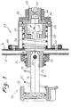
- Fig. 1 whose scale is larger than that of the other figures, shows a horizontal one Section through a closure for the hood of a vehicle in the installed condition.
- the hood 2 and the vehicle frame 4 shown in the figure are only indicated schematically, are designed so that the bonnet 2 is pulled down over the front end of the vehicle frame 4, the bonnet 2 relative to the vehicle frame 4 perpendicular to the plane of the drawing Fig. 1 is pivotable or attachable.
- the closure consists of a unit attached to the hood 2 10 and a unit 11 fastened to the vehicle frame 4.
- the arrangement is taken so that the units 10 and 11 on one to the longitudinal axis of the vehicle parallel common horizontal axis A when the hood 2 is pivoted down. This is shown in Fig. 1, in which the closure in in its open state.
- the hood-side assembly 10 consists of a fastening part 12, one Nut 14 and a locking bolt 16, at one end a pin 20 attached and the other end carries an operating button 18.
- the fastener 12 is attached to the hood 2 in that the sleeve-shaped fastening part 12 inserted through a hole in the bonnet and using flanges 24 (see FIG. 5) and the nut 14 braced with the sheet metal of the bonnet 2 is.
- the locking bolt 16 is in a bore 26 of the fastening part 12 along the axis A slidably guided.
- the pin 20 runs across the axis A through the Locking pin 16 and its two ends protrudes from the locking pin 16 so that it forms two locking projections 20a and 20b (Fig. 7). With the help of the locking projections 20a, 20b is the locking bolt 16 in longitudinal grooves 28 of the fastening part 12 (Fig. 5) secured against rotation as long as the locking pin 16 in the open position shown in Fig. 1.
- the locking bolt 16 is the opening spring designed as a coil spring 22, which is clamped between the nut 14 and the actuating button 18 is biased into its open position in which the two locking projections 20a, 20b of the locking bolt 16 on a shoulder 30 of the fastening part 12 (see also Fig. 5).
- the operating button 18, for example consists of plastic and molded by injection molding on the locking pin 16 has such a shape that it can be gripped comfortably with one hand, as can be seen in particular from FIGS. 1, 2 and 4.
- the frame-side assembly 11 consists of a receiving part 32, one Closure element 34, a closing spring 36, an adjusting element 38 and one Retaining plate 40.
- the cup-shaped receiving part 32 is at its open End screwed to the vehicle frame 4 by means of a mounting flange 42.
- the receiving part 32 has a sleeve-shaped Approach 44 provided, in which the adjusting element 38 is screwed.
- the adjustment element 38 is provided in the interior of the receiving part 32 with a flange 46, which forms a stop surface 48 on its end face, its function in the following is explained in more detail.
- the closure element 34 is designed as a socket, on the one in FIG. 1 an annular flange 51 is provided on the right-hand end. With the help of the ring flange 51 is the closure element 34 in a bore 49 of the receiving part 32 in the direction the axis A slidably guided.
- the ring flange 51 engages as Coil spring trained closing spring 36, such that the closing spring 36 the Locking element 34 in contact with the stop surface 48 of the adjusting element 38 presses when the shutter is in the open state (Fig. 1).
- To the Flange 51 has two radially projecting guide projections 52 (FIG. 6), which are guided in the longitudinal grooves 50 of the receiving part 32 and thus the closure element 34 secure against twisting.
- the closing spring 36 lies with its in FIG. 1 left-hand end on the holding plate 40.
- the holding plate 40 is basically only needed during assembly to support the closing spring 36, because in the built-in State of the closing spring 36 ultimately from the sheet metal of the vehicle frame 4 is held.
- the closure element 34 is at its (in FIG. 1) left-hand end an annular portion 53 of reduced diameter.
- the ring-shaped Section 53 forms a push-through opening 54 (see also FIG. 6), the one has a keyhole-like shape, such that the locking bolt 16 with its fits two locking projections 20a, 20b through the push-through opening 54, if the adjusting bolt 16 using the actuating button 18 along the axis A is moved to its right end position, in which the operating button 18 on the Mother 14 is present.
- the annular portion 53 of the closure member 34 is at its from the hood 2 facing away from the inner side with a shoulder 56. How 6, shoulder 56 has two diametrically opposed ones Ramp surfaces 58 are provided, each with a locking recess 60 connects.
- the locking recesses 60 are on their from the ramp surfaces facing away from the limit stops 62, that of radial planes lying surfaces 63 are formed, the axially further inside than the ramp surfaces 58 lie.
- the ramp surfaces 58 and the latching depressions 60 also form the locking projections 20a, 20b of the locking bolt 16 a cam-locking connection, which locks the locking element 34 and the locking bolt 16 together, when the locking pin 16 in its bonnet 2 keeping closed Closed position is moved, as will be explained in more detail below.
- the closure works as follows. It is assumed that the units 10 and 11 are in the state shown in FIG. 1 by the bonnet 2 is folded down and the closure is in the open state located. To close the closure, the locking bolt 16 is also used With the help of the operating button 18 against the force of the opening spring 22 axially moved inwards (to the right in Fig. 1), initially through an opening 6 in the sheet metal of the vehicle frame 4 and then through the push-through opening 54 of the closure element 34 is moved through. If the operating button 18 in contact with the nut 14, the locking bolt 16 with the help of the operating button 18 rotated about its longitudinal axis.
- the locking projections slide 20a, 20b on the inclined ramp surfaces 58, so that the closure element 34 against the force of the closing spring 36 to the outside (to the left in FIG. 1) is pulled and thus lifted off the stop surface 48.
- the Rotational movement by approximately 90 ° latches the locking projections 20a, 20b in the corresponding shaped locking recesses 60, whereby the locking bolt 16 in its Locked position is locked.
- the locking pin 16 is now from the locking element 34 under the Effect of the closing spring 36 held in its closed position, in which he the hood 2 keeps closed.
- the force of the closing spring 36 is several times greater than the force of the opening spring 22.
- the force of the closing spring 36 between 130 and 150 N, while the Force of the opening spring 22 is less than 30 N.
- the adjusting element 44 is provided with a recess 45 so that the adjusting element 38 can be adjusted by a tool along the axis A. On in this way the stop surface 48 and thus the position of the closure element 34 adjust relative to the assembly 10 to by manufacturing tolerances conditional fluctuations in the distance between the hood 2 and the vehicle frame 4 compensate.
- the closing and opening of the closure is therefore extremely easy because Just close an axial movement and a 90 ° rotation and to open only a 90 ° rotation of the locking bolt 16 is required, the operation takes place only from outside the vehicle.
- the end positions the locking bolt 16 in the open and closed state are accurate Are defined.
- the locking projections snap in the closed state 20a, 20b in the locking recesses 60 of the closure element 34, what is clearly noticeable.
- a further rotation of the locking bolt 16 over the locking position is also due to the limit stops formed by the surfaces 63 62 prevented.
- the end position of the locking bolt 16 in the open state is by the engagement of the locking projections 20a, 20b on the shoulder 30 of the fastening part 12 defines, the opening spring 22 ensures that the locking bolt 16 is completely moved out of the assembly 11.
- the above measures ensure a high level of functional reliability of the closure guaranteed. Operating errors are practically impossible because on the one hand the end positions of the locking bolt 16 are precisely defined and on the other hand unintentional or undesired rotations of the locking bolt 16 and the closure element 34 can be prevented. In addition, the closure has a high level of security against the effects of dirt.
Landscapes
- Engineering & Computer Science (AREA)
- Mechanical Engineering (AREA)
- Lock And Its Accessories (AREA)
- Superstructure Of Vehicle (AREA)
Applications Claiming Priority (2)
| Application Number | Priority Date | Filing Date | Title |
|---|---|---|---|
| DE19833727 | 1998-07-27 | ||
| DE19833727A DE19833727A1 (de) | 1998-07-27 | 1998-07-27 | Verschluß für eine Motorhaube |
Publications (2)
| Publication Number | Publication Date |
|---|---|
| EP0976901A2 true EP0976901A2 (fr) | 2000-02-02 |
| EP0976901A3 EP0976901A3 (fr) | 2001-04-18 |
Family
ID=7875434
Family Applications (1)
| Application Number | Title | Priority Date | Filing Date |
|---|---|---|---|
| EP99112958A Withdrawn EP0976901A3 (fr) | 1998-07-27 | 1999-07-05 | Fermeture d'un capot |
Country Status (2)
| Country | Link |
|---|---|
| EP (1) | EP0976901A3 (fr) |
| DE (1) | DE19833727A1 (fr) |
Cited By (1)
| Publication number | Priority date | Publication date | Assignee | Title |
|---|---|---|---|---|
| FR2944545A1 (fr) * | 2009-04-20 | 2010-10-22 | Reel | Dispositif pour assurer le verrouillage/deverrouillage d'un element sur et hors d'une structure. |
Family Cites Families (5)
| Publication number | Priority date | Publication date | Assignee | Title |
|---|---|---|---|---|
| DE7247162U (de) * | 1973-05-30 | Ymos Metallwerke Wolf & Becker Gmbh & Co | Vorrichtung zum Öffnen und Schließen, insbesondere für Kofferraumdeckel von Kraftfahrzeugen | |
| DE410701C (de) * | 1924-02-09 | 1925-03-12 | Bardin Soc Nouv Ets | Motorhaubenverschluss an Kraftfahrzeugen |
| DE708599C (de) * | 1936-09-20 | 1941-07-24 | Beschlagfabrik Benninghoven Ko | Verschluss fuer die Motorhaube oder fuer Koffertueren u. dgl., insbesondere an Kraftfahrzeugen |
| BE755983A (fr) * | 1969-09-17 | 1971-03-10 | Dzus Fastener Co | Verrou de capot d'automobile |
| DE2313337A1 (de) * | 1973-03-17 | 1974-09-19 | Ymos Metallwerke Wolf & Becker | Vorrichtung zum oeffnen und schliessen, insbesondere fuer kofferraumdeckel von kraftfahrzeugen |
-
1998
- 1998-07-27 DE DE19833727A patent/DE19833727A1/de not_active Withdrawn
-
1999
- 1999-07-05 EP EP99112958A patent/EP0976901A3/fr not_active Withdrawn
Cited By (5)
| Publication number | Priority date | Publication date | Assignee | Title |
|---|---|---|---|---|
| FR2944545A1 (fr) * | 2009-04-20 | 2010-10-22 | Reel | Dispositif pour assurer le verrouillage/deverrouillage d'un element sur et hors d'une structure. |
| WO2010122267A3 (fr) * | 2009-04-20 | 2011-03-17 | Renault Sas | Dispositif pour assurer le verrouillage/deverrouillage d'un element sur et hors d'une structure |
| CN102405324A (zh) * | 2009-04-20 | 2012-04-04 | 雷诺股份公司 | 用于使构件能在结构上或从结构锁定/解锁的设备 |
| US8801321B2 (en) | 2009-04-20 | 2014-08-12 | Renault S.A.S. | Device for enabling the locking/unlocking of a member on and out of a structure |
| CN102405324B (zh) * | 2009-04-20 | 2015-02-18 | 雷诺股份公司 | 用于使构件能在结构上或从结构锁定/解锁的设备 |
Also Published As
| Publication number | Publication date |
|---|---|
| EP0976901A3 (fr) | 2001-04-18 |
| DE19833727A1 (de) | 2000-02-03 |
Similar Documents
| Publication | Publication Date | Title |
|---|---|---|
| DE19514944C1 (de) | Selbstjustierender Dämfungsanschlag für bewegliche Teile | |
| DE60036005T2 (de) | Riegel | |
| DE69703459T2 (de) | Verriegelung von sich gegenüber stehenden Zahnstangen für eine einstellbare Lenksäule | |
| DE102008022096B4 (de) | Verriegelungseinstellklemme | |
| EP1898105A2 (fr) | Fermeture rapide destinée à la liaison de deux composants | |
| DE60103834T2 (de) | Mechanisches Modul für einen Schlüssel, Schlüssel mit einem solchen Modul und Verfahren zur Befestigung eines solchen Moduls an einem Schlüssel | |
| DE3924230C2 (de) | Türverriegelungsvorrichtung zur Verwendung in einer Fahrzeugkarosserie | |
| DE4141007C2 (de) | Einrichtung zum Sickern einer Vorrichtung zum Verbinden einer Schalthebelanordnung mit einem Lenkschloß | |
| DE102018108829A1 (de) | Halteelement | |
| DE3917967C2 (de) | Feststeller für eine Deckel- oder Haubenanlenkung an Kraftfahrzeugen | |
| EP0840336A2 (fr) | Commutateur à poussoir autoréglable, en particulier un contacteur de stop | |
| EP0239767A1 (fr) | Verrouillage rotatif pour la connection des éléments en forme des plaques | |
| EP1882798B1 (fr) | Ferrure pour porte ou fenêtre | |
| WO2019238162A1 (fr) | Serrure de véhicule automobile | |
| EP0754827A2 (fr) | Dispositif pour la fixation amovible et axialement non coulissante d'une poignée sur un élément de palier, notamment pour une poignée de porte ou fenêtre | |
| DE6808242U (de) | Verschlussvorrichtung fuer lineare bewegungsmechanismen | |
| EP0976901A2 (fr) | Fermeture d'un capot | |
| EP2034109A2 (fr) | Dispositif de sécurité | |
| EP0569931B1 (fr) | Poignée | |
| EP1574641B1 (fr) | Dispositif de fermeture pour conteneurs, portes, armoires, meubles ou similaires | |
| DE102018119638A1 (de) | Fahrzeuginnenraumkomponente zur Anbringung an einer Fahrzeugkarosserie | |
| EP0215295A1 (fr) | Accouplement pour l'assemblage détachable d'un manche de pièce à main dentaire avec une tête | |
| DE102022108600A1 (de) | Selbsteinstellende Abstandhaltervorrichtung | |
| EP0358101B1 (fr) | Fiche pour connexion | |
| EP2034110B1 (fr) | Rosette avec dispositif de fixation |
Legal Events
| Date | Code | Title | Description |
|---|---|---|---|
| PUAI | Public reference made under article 153(3) epc to a published international application that has entered the european phase |
Free format text: ORIGINAL CODE: 0009012 |
|
| AK | Designated contracting states |
Kind code of ref document: A2 Designated state(s): DE FR GB IT |
|
| AX | Request for extension of the european patent |
Free format text: AL;LT;LV;MK;RO;SI |
|
| PUAL | Search report despatched |
Free format text: ORIGINAL CODE: 0009013 |
|
| AK | Designated contracting states |
Kind code of ref document: A3 Designated state(s): AT BE CH CY DE DK ES FI FR GB GR IE IT LI LU MC NL PT SE |
|
| AX | Request for extension of the european patent |
Free format text: AL;LT;LV;MK;RO;SI |
|
| 17P | Request for examination filed |
Effective date: 20010511 |
|
| AKX | Designation fees paid |
Free format text: DE FR GB IT |
|
| STAA | Information on the status of an ep patent application or granted ep patent |
Free format text: STATUS: THE APPLICATION IS DEEMED TO BE WITHDRAWN |
|
| 18D | Application deemed to be withdrawn |
Effective date: 20040203 |