EP0974061B1 - Magazin zur bevorratung von testelementen - Google Patents
Magazin zur bevorratung von testelementen Download PDFInfo
- Publication number
- EP0974061B1 EP0974061B1 EP98919244A EP98919244A EP0974061B1 EP 0974061 B1 EP0974061 B1 EP 0974061B1 EP 98919244 A EP98919244 A EP 98919244A EP 98919244 A EP98919244 A EP 98919244A EP 0974061 B1 EP0974061 B1 EP 0974061B1
- Authority
- EP
- European Patent Office
- Prior art keywords
- magazine
- test
- test elements
- roller
- slide
- Prior art date
- Legal status (The legal status is an assumption and is not a legal conclusion. Google has not performed a legal analysis and makes no representation as to the accuracy of the status listed.)
- Expired - Lifetime
Links
Images





Classifications
-
- G—PHYSICS
- G01—MEASURING; TESTING
- G01N—INVESTIGATING OR ANALYSING MATERIALS BY DETERMINING THEIR CHEMICAL OR PHYSICAL PROPERTIES
- G01N33/00—Investigating or analysing materials by specific methods not covered by groups G01N1/00 - G01N31/00
- G01N33/48—Biological material, e.g. blood, urine; Haemocytometers
- G01N33/483—Physical analysis of biological material
- G01N33/487—Physical analysis of biological material of liquid biological material
- G01N33/4875—Details of handling test elements, e.g. dispensing or storage, not specific to a particular test method
- G01N33/48757—Test elements dispensed from a stack
-
- G—PHYSICS
- G01—MEASURING; TESTING
- G01N—INVESTIGATING OR ANALYSING MATERIALS BY DETERMINING THEIR CHEMICAL OR PHYSICAL PROPERTIES
- G01N35/00—Automatic analysis not limited to methods or materials provided for in any single one of groups G01N1/00 - G01N33/00; Handling materials therefor
- G01N35/00029—Automatic analysis not limited to methods or materials provided for in any single one of groups G01N1/00 - G01N33/00; Handling materials therefor provided with flat sample substrates, e.g. slides
-
- G—PHYSICS
- G01—MEASURING; TESTING
- G01N—INVESTIGATING OR ANALYSING MATERIALS BY DETERMINING THEIR CHEMICAL OR PHYSICAL PROPERTIES
- G01N35/00—Automatic analysis not limited to methods or materials provided for in any single one of groups G01N1/00 - G01N33/00; Handling materials therefor
- G01N35/00029—Automatic analysis not limited to methods or materials provided for in any single one of groups G01N1/00 - G01N33/00; Handling materials therefor provided with flat sample substrates, e.g. slides
- G01N2035/00089—Magazines
-
- G—PHYSICS
- G01—MEASURING; TESTING
- G01N—INVESTIGATING OR ANALYSING MATERIALS BY DETERMINING THEIR CHEMICAL OR PHYSICAL PROPERTIES
- G01N35/00—Automatic analysis not limited to methods or materials provided for in any single one of groups G01N1/00 - G01N33/00; Handling materials therefor
- G01N35/00029—Automatic analysis not limited to methods or materials provided for in any single one of groups G01N1/00 - G01N33/00; Handling materials therefor provided with flat sample substrates, e.g. slides
- G01N2035/00099—Characterised by type of test elements
- G01N2035/00108—Test strips, e.g. paper
- G01N2035/00118—Test strips, e.g. paper for multiple tests
Definitions
- test elements such as Detection of analytes in sample liquids can be used.
- test elements are used particularly in the field of urine analysis and in the field of blood sugar determination used.
- test elements are used extensively in environmental analysis used. Another area, the importance of which is increasing, concerns immunological tests, e.g. detection of drugs, HCG and HIV in blood or urine.
- test element To carry out the detection of an analyte or the analysis of a sample liquid the test element is brought into contact with a sample. It can be, for example a surface can be rubbed with the test element.
- a sample can be, for example a surface can be rubbed with the test element.
- the normal scope of test elements lies in the analysis of sample liquids, including the sample liquid is either given up on the test element (especially provisions from Blood, serum, cerebrospinal fluid) or the test element is immersed in the sample liquid (especially urine).
- test elements must be protected against moisture in order to avoid reagent degradation. This applies equally to the so-called optical test strips in which a color change occurs due to the reaction of an analyte with the sample is caused, as well as for so-called sensor elements, in which one chemical change of the test element caused by the sample electrochemically is evaluated. Furthermore, it is usually necessary to pre-test elements Protect mechanical influences and dirt to ensure reliable analysis results sure.
- test elements There are several types of test elements in the prior art known. In the first procedure, the test elements are loosely in a vessel, for example in a tube, which is closed by a stopper or the like can be. Furthermore, it is known to test elements individually in water vapor tight Seal foils.
- test elements mechanically from the storage container or the sealing film.
- a mechanical removal of test elements are in State of the art known a number of magazines, such as those in the patents U.S. 5,102,624, U.S. 5,154,889, U.S. 3,918,910, U.S. 4,911,344 and U.S. 4,142,863 are.
- This type of magazine uses test elements that are stacked on top of each other are.
- the test elements described in these U.S. patents are special adapted for use in a magazine, d. H. they have a uniform thickness and can be moved against each other without snagging or jamming.
- test elements on the market does not have a uniform height profile on and can therefore not be used easily in the magazines of the prior art become.
- US Pat. No. 3,918,910 a magazine is described which is used for Storage of test elements is suitable in which several detection zones are on one carrier are upset. Due to the manufacturing process, the detection zones are above the Carrier over and thus cause a varying height structure of the test element.
- a magazine is shown for stocking such test elements is suitable. In this magazine the test elements are stacked on top of each other, so that the top and bottom of successive test elements come to rest against each other.
- the stack of test elements is made up of spring elements pressed in the direction of an area from where the removal of a test element by Slide out or pull out. Experimental studies have shown that such magazines are very prone to errors. Failures often occur where none of the test elements can be safely gripped by the removal unit or incorrectly carried two test elements out of the magazine together become.
- the object of the present invention was to provide a magazine, which with the test elements widely used in trade with an uneven height profile are reliable is working. Furthermore, it was an object of the present invention to provide a magazine with which a mechanical removal is possible and a high packing density of the test elements.
- Another object of the present invention was to propose a system that through the interaction of a magazine and a removal device an automated Providing test elements.
- the object of the invention is achieved by a magazine for storing test elements solved, which has at least a pair of opposite guide grooves into which the Test elements are inserted so that they are directly next to each other and edges are adjacent Collide test elements.
- the present invention further includes a system for providing Test elements with a magazine with at least two opposing guide grooves, are inserted into the test elements so that they are directly next to each other in a surface lying and edges of adjacent test elements abut each other as well as a slide that at one end of the layer formed by the test elements and the test elements moves along the grooves towards the opposite end of the sheet.
- the present invention therefore proposes a magazine in which the test elements are guided in guide grooves and are arranged so that edges neighboring test elements come to lie directly against each other.
- the present invention takes advantage of the fact that the test elements, due to their manufacture, are precisely defined and have a constant width over the length of the test strip.
- the magazine of the present invention is for storage test elements that are flexible and / or have an uneven height profile have.
- a system is also described with the removal of test elements from the magazine according to the invention is possible.
- FIG. 1A and 1B of the present application are commercially available test elements shown.
- Figure 1A shows a test element in supervision.
- the test element (1) has a carrier (2) on which several test zones (3) are applied.
- the rectangular shown Test element has a shorter side, which is referred to below as the width, and a longer side called the length.
- 1B is a side view of a test element. You can clearly see the different height of the test zones (3) and a bend in the test element.
- the test element can bend be due both to the properties of the carrier (2) and the type of application the test zones (3).
- With a particularly favorable method of manufacturing test elements the test zones are applied to the carrier and then with a fine Net covered. This procedure is described, for example, in US Pat. No. 3,802,842.
- a magazine according to the invention for storing test elements has at least one Pair of opposing guide grooves into which the test elements to be stored are inserted become.
- the guide grooves guide a test element on each of the two opposite ones End up. If several test elements are inserted one after the other into a guide groove, so the test elements come to lie side by side and the long edges of the Carriers of neighboring test elements touch each other.
- the distance of the opposite Guide grooves are selected according to the length of the test elements.
- the distance between the groove bases (most distant regions of the grooves) preferably corresponds to the Length of a stretched test element.
- the depth of the grooves and the spacing of the grooves determine the length of the test element section that is guided through the groove.
- the guided one Length of the test elements equal to the groove depth.
- the test elements are further apart, so the test elements have a play in their longitudinal direction and the guided length corresponds to that Groove depth minus this game.
- This Play is advantageously 0.5 to 20% of the test element length. It turned out to be it is usually sufficient to run the test elements over a length of 0.3 cm.
- the test strip sections that are passed through the grooves are 0.4 to 1.0 cm long.
- such embodiments are also to be included in which the Both grooves are so deep that they take up half of the test strip and the Grooves continue to be connected so that there is a coherent slot results.
- a slot is a special embodiment understood a pair of grooves.
- Such a slot for guiding the test elements is favorable because it can be used to suppress the curvature of the test elements, because the test elements are guided along their full length. production wise however, magazine designs are more advantageous in which the grooves have a depth of less than 2 cm.
- the length of the grooves determines the number of test elements that are recorded can.
- the length of the grooves is hardly restricted. However, they are groove lengths between 5 and 15 cm cheap because they are easy to handle, compact magazines to lead.
- slots instead of grooves
- the length of which is essentially limited in terms of tool technology, since it is difficult to use forming tools available for long slot lengths, for example above 10 cm put.
- this difficulty is eliminated and one is in the groove length is hardly limited. In both cases, i.e. H. both when using grooves as well as slots, it must be ensured that the grooves or the slot ends in run essentially parallel to prevent jamming or falling out of test elements to avoid.
- the magazine has pairs of one above the other Has guide grooves, so that the storage of test elements arranged one above the other Layers is possible, which increases the capacity of the magazine from which Handling has proven to be favorable if a magazine has 8 to 15 layers of test elements has.
- a magazine has 8 to 15 layers of test elements has.
- the magazine was in addition to an order and an availability of test elements can perform the task, the test elements from moisture as well as to protect mechanical influences.
- the magazine can therefore walls own that complete the interior from the exterior.
- the magazine must have one or more openings. These openings can by a mechanical closure, such as a hinged lid or a glued-on sealing foil.
- a mechanical closure such as a hinged lid or a glued-on sealing foil.
- the guide grooves are in the side walls of the magazine integrated. Furthermore, these side walls can be used during the Manufacturing process through additional walls, in particular top and bottom walls, with each other be connected. Such arrangements can preferably be produced in one piece.
- the injection molding process is particularly suitable for this. In terms of tools, it can however, it would be cheaper to individually shape the walls of the magazine (advantageously by injection molding). Because the grooves on one side of the magazine are formed by one half of the tool the individual grooves have only small tolerances to one another. If the Magazine parts are formed individually, so the side walls, top and are advantageous Bottom, front and back are identical, so that the same tools are used can be.
- the cassette is put together from n + 1 injection molded parts, where n is the number of strip layers. All parts are the same (repeat parts). They are flat frames that are demolded in an injection molding process without a slide can. If they are put together flat (clipped, ultrasonically welded) or glued), two pieces each form the opposing grooves for one layer Strips. It is favorable if the frames have two recesses. From each The smaller recess of the frame forms a shaft open at the top and bottom, in a bag of desiccant can be placed. This can, for example, by a Paper sleeve be prevented from falling out.
- the magazine has openings. It has proven to be advantageous if one or several openings are integrated in a side wall of the magazine. Such an opening is at the level of a groove, so that a test element that is adjacent to the groove the opening is located by moving it along its longitudinal axis from the magazine can be.
- the opening preferably has a rectangular cross section whose height is 10 to 50% greater than the maximum height of the test elements and whose width is 10 to 50% larger than the width of the test elements.
- each pair of grooves preferably has one such removal opening.
- each of the pairs of grooves has one has another opening in the opposite side wall through which a slide in the magazine can penetrate to eject a test element.
- the above Openings in a magazine that is put on the market can be made using sealing foils be at least partially closed. These sealing films can be used before subtracted from. However, it is advantageous if the sealing films are pushed through the slide or an emerging test element can be pierced.
- the removal takes place of test elements by moving the test elements over the end of the groove (in the longitudinal direction the grooves) d. H. there is a displacement transverse to the longitudinal axis of the test elements instead of.
- the grooves of a pair of grooves are on one side open so that test elements can be pushed out over the end of the groove.
- the Magazine therefore has an end face that runs transversely to the side walls of the magazine and in which there is an opening for the exit of test elements per pair of grooves.
- This Outlet openings preferably have a rectangular cross section, the width of which is about 10 to 30% greater than the maximum height of the test elements and their length by 0.5 to Is 20% longer than the test strip length.
- the magazine has no end wall and the end face is to transport the magazine just sealed with a sealing film.
- the sealing film can serve to close the front wall against the ingress of moisture. Will the However, moisture protection is implemented in a different way (e.g. by repackaging) the sealing film can be omitted if necessary. It has been particularly effective it turned out, however, the areas of the end face in which the groove ends are located, to cover with a foil. On the one hand, the test elements are prevented from falling out, on the other hand, the test elements can pierce the film.
- a special Advantage of this embodiment is that the film only in the area of Location is opened, from which a removal takes place. The remaining (still complete) layers of test elements are still protected by the film, so that when the Magazine no test elements can fall out.
- the Test elements can either be transported to a removal position or directly be ejected from the magazine.
- the magazine is like this arranged that the grooves are vertical and the test elements in the grooves through the Gravity can be transported down.
- a removal position or the magazine is open so that the test elements can exit directly from the magazine.
- a closure is present which prevents test elements from falling out in an uncontrolled manner and enables gradual removal.
- the magazine preferably contains one or more spring elements in its interior the ensemble of test elements, which is located in a pair of grooves, together in the direction transport to a removal position.
- spring elements can, for example Coil springs that are at the end of each groove facing away from the removal position are arranged. Spring elements further stabilize the arrangement of the test elements, even if the magazine is not completely filled. It is thus avoided that the Put test elements across or get messed up in another way, which affects reliability of a magazine would greatly decrease.
- the magazine has at least one a recess in the top or bottom through which a slide in the magazine can be introduced.
- a slide it is possible to transport the To carry out test elements from outside.
- the slide can be on the outside of the magazine be attached so that it can be moved manually by a user.
- the slide belongs to an analysis device that contains test elements is working.
- the slide is driven by a drive unit belonging to the analysis device controlled so that the removal of test elements by the analyzer can be controlled. In this way it can be achieved that test elements only then can be taken from the protective magazine if they are required by the analyzer.
- a unit including a magazine and a slide, for the removal of test elements serves, forms a system for the provision of test elements, which also The subject of this invention is.
- a magazine with at least one belongs to this system two opposite guide grooves into which the test elements are inserted so that they lie directly next to each other in a surface, and the edges of neighboring test elements abut.
- the system also includes a slider, which at one end of the through the test elements formed surface attacks and the test elements transverse to their longitudinal axis moves towards the opposite end of the surface.
- said slider preferably engages through a recess in a Magazine wall in the magazine. The recess required for this becomes as small as possible held to minimize moisture penetration into the magazine.
- the recess is a slot that is parallel to the grooves in the top or bottom of the Magazine runs.
- the slot can have rubber lips on the opposite long sides own, which lie against each other in the rest position and thus penetration of moisture prevent as much as possible.
- the slide is incrementally moved by a distance, that essentially corresponds to the width of a test element, so that the test elements brought into a removal position one after the other or directly from the magazine be ejected.
- the drive unit for the slide can, for example, be a nut be on a threaded rod.
- the threaded rod can have a stepper motor can be rotated, which in turn is controlled by a control unit.
- the control unit with the control unit Analyzer is connected so that the time of removal can be controlled appropriately can.
- the slide for example in the form of a metal pin, be attached directly. A rotation of the threaded rod causes a linear feed of the Pen that is used to move the test elements.
- the depth of penetration the slide in the magazine can be controlled.
- the slider first penetrates so deep into the magazine that it is level a first layer (level) of test elements, and transports this in this level located ensemble of test elements, so that the individual test elements successively in reach a removal position. After completely emptying this position, the Slide back, the depth of penetration is increased so that it is at the level of a second Location of test elements and the removal process is repeated. Corresponding more layers of test elements can be emptied.
- test elements For the successive removal of test elements from the magazine, it is important that the Moving the test elements into the removal position within the magazine as well as the The test elements are removed from this position in a coordinated manner.
- a second element can be used to remove test elements from the removal position Slide take place along the respective test element located in the removal position shifts its longitudinal axis and thus pushes it out of the magazine. Farther can be removed by inserting a gripper into the magazine and a Pulls the test element out of the removal position.
- the test element is first inserted by a slide Piece is moved along its longitudinal axis, so that the test element better from a Handling unit can be taken.
- a system with a device according to the invention is also used Magazine and a slide to move the test strip layers and one Roller with at least one groove into which a test element is pushed and rotated the roller can be transported, described.
- the magazine is preferably located and an area of the roller in a moisture-tight sealed housing, so that the Test elements in the magazine cannot be destroyed by moisture.
- Figure 1 shows a test element in supervision. There are also the carrier (2) and the test zones (3) recognizable. A further test element is shown in side view in FIG. 1B. In particular, FIG. 1B shows the different heights of the test zones (3) and the Bending of the beam (2).
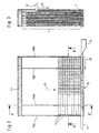
- FIG. 2 shows a magazine along a position (plane) of test elements (1).
- the test elements are arranged side by side in the same direction in the magazine.
- the side walls (10a) and (10b) are the grooves for receiving the test elements.
- a desiccant chamber (11) which serves in the Magazine to absorb penetrated moisture.
- desiccants are in the state of the Technology known substances, e.g. B. silica gels or molecular sieves can be used.
- the Desiccant chamber (11) closes the back of the magazine so that no openings stay behind to prevent moisture from entering.
- FIG. 2 shows an already half-emptied layer of test elements.
- the test elements are from the back of the magazine towards the front (12) moves, as indicated by the arrow (13). That of the front
- the closest test element (1 ') is in the removal position.
- the test element (1 ') by an ejection slide (14) in the arrow (15) Direction pushed out of the magazine.
- the magazine in the right side surface (10b) an opening through which the ejection slide (14) into the magazine can penetrate.
- the magazine has an opening in the left side surface (10a), through which the test element (1 ') can emerge from the magazine.
- Figure 3 shows a section through the magazine of Figure 2 along the line (A - A ').
- Figure 3 is the slide (17) for advancing the test elements in the direction of the removal position shown.
- the groove length (L) can also be seen from FIG.
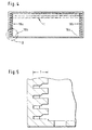
- FIG. 4 shows an illustration of the magazine from FIG. 2 along the section line (BB ′).
- BB ′ shows the pairs of grooves (18a, 18b) in which the test elements be performed.
- Each pair of grooves includes two mutually opposite grooves
- the magazine shown in Figure 4 has 12 such pairs of grooves, so that test elements can be stored in 12 levels or layers.
- FIG. 5 shows an enlarged detail (5-fold) of the area (X) in FIG. 4 in which the structure of the grooves used here can be seen more precisely.
- the grooves shown have a depth (T) into which the test element ends are inserted. It is from the Figure 5 shows that each of the grooves has a narrower and a wider part. This is advantageous if the test zones on the carrier are close to one end of the test element come close. In this case, a groove with two thickness ranges can advantageously be used so that the outermost end of the test element, which is not covered by a test zone is passed through the narrower area of the groove, and still an adjacent one Area in which a test zone is located is led through the wider area of the groove can be.
- the distance between the grooves shown in FIG. 5 is approximately 2 mm. Such a small distance can be realized in spite of a bending of the test elements without the danger there is a hooking of adjacent levels of test elements.
- FIG. 7 shows an exploded drawing of a magazine, which consists of individual frames (20) is put together or clipped together.
- the frames are like this in the example shown procure that the lateral edge (21) is raised compared to a shoulder (22). The bottom the frame is essentially in the area of the edge (21) and the shoulder (22) planar, so that when two or more frames are stacked on top of one another, a groove results, through the heel (22) and the overlying floor area of the next frame is formed.
- the frames have a front part in which the grooves are located, and a rectangular recess (23). This leads in the assembled magazine a cavity filled with a desiccant or a desiccant container can be.
- the frames (20) can also have slots (24) (in the example shown two) have a slider for moving the test elements.
- FIG. 8 shows a system for making test elements available.
- the FIGS. 8A to 8E show the steps which are carried out when a test element is removed become.
- the system shown in FIG. 8A has a magazine (30) in which several layers of edge-to-edge test elements are arranged.
- This Magazine corresponds essentially to that shown in Figure 3. In particular, they are Grooves of the magazine on the side facing away from the desiccant (60) open so that Test elements by moving a layer of test elements successively from the magazine can be transported out.
- the magazine has an or on the underside several slot (s) through which the slide (s) (31) can engage in the magazine.
- the slide is in turn rotatable about an axis (32) with a movable slide (33) connected.
- the magazine (30) is moved to a height, in the one layer of test elements at the level of the front end (31a) of the Slide comes to rest. Now the slide in the direction of the position of Test elements shifted, for which the slide is moved.
- the slide engages as in FIG. 8A shows the position of test elements and shifts the entire layer, whereby the test elements move in their transverse direction towards the open end of the magazine become.
- a rotatable roller arranged, which has at least one groove for receiving a test element.
- the roller has two grooves of essentially the same geometry.
- the roller (40) For removal of a test element, the roller (40) is rotated so that the at least one groove (41) located at the level of the test strip moved by the slide.
- the Slider By moving the Slider becomes the most distant test element in the groove (41) pushed in.
- Figure 8B shows a state in which the said test element already in the groove.
- the test element is moved by the movement of the slide (33) pushed up to the end of the groove (41) and further movement of the slide (33) leads, because the position of the edge on edge arranged test elements does not compress arbitrarily can be to a rotation of the slide (31) about the axis (32).
- the slide is held in its rest position by a spring (34) and is moved out
- a sensor (35) detects from the rest position by rotating around the axis.
- This sensor can be a light barrier, for example, the light path of which is immersed of the rear end (31b) of the slide is interrupted. This interruption can be detected with a control device and the displacement of the slide (33) in Direction on the roller (40) can be stopped. With this device, a Test element from the magazine can be pushed safely and completely into the groove without that the width of the test element needs to be known. Thus the device largely independent of fluctuations in the test element width, the production technology is almost inevitable. Starting from the position shown in Figure 8B the carriage will move in the opposite direction, releasing the pressure from the Location of the test elements is removed and the slide in relation to its rest position the rotation around the axis (32) returns. The one now in the roller Test element can be removed by rotating the roller.
- the magazine and the part of the test element used for removing a test element are located Roller inside a moisture-proof housing (50).
- a moisture-proof housing 50
- the test elements in the magazine are not decomposed by moisture.
- This is preferably additionally achieved by a desiccant belonging to the magazine (60) ensured.
- the groove for receiving a test element both within the Housing (50) as well as outside of it need special precautions be taken to the area of the roller against moisture penetration seal. This can be done for example by rubber lips or the like lie close to the roller and also provide a moisture seal if the Roller is rotated.
- the groove is loaded with a test element under one The rubber lip must be screwed through, the structure shown in Figure 8 has found to be more suitable for preventing moisture penetration.
- the housing (50) has protective parts (50a, 50b) which are so opposite to the outer peripheral surface of the Roller (40) are arranged so that the roller surrounds as closely as possible in these areas is.
- the gaps between the protective parts (50a, 50b) and the roller (40) enable smooth rotation of the roller and ensure that test elements, that protrude beyond the outer contour of the roller can be transported non-destructively can.
- the gap between the protective parts and the roller provides a creepage distance Moisture through which a certain amount of moisture can penetrate. That amount is however, it is so small that it does not give rise to rapid decomposition of the test elements.
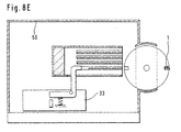
- FIG. 8D shows how the test element located in the groove can be turned the roller is transported through the gap between the protective part (50a) and the roller. It can be seen in FIGS. 8C and 8D that the test element is slightly above the The outer contour of the roller protrudes. This corresponds to a preferred embodiment in which the depth of the groove is less than the smallest expected test element width. hereby it is ensured that each test element is at least slightly over the outer contour of the Roll protrudes and therefore no subsequent test element together with the one already in the test element located in the groove penetrates into the groove. Such a situation is too Avoid turning the roller to a system failure due to jamming or would lead similar.
- a 180 ° is used to remove a test element from the magazine. Rotation of the roller used to move the test element to the position shown in Figure 8E from which it can be picked up with a gripper arm or the like.
- FIG. 9 shows the roller (40) in a perspective view.
- a groove (41) is formed in the outer peripheral surface of the roller and runs parallel to the axis of the roller.
- the roller advantageously has one or more slots (42) which are substantially perpendicular to the axis of the roller.
- the slots (42) extend from the surface of the roller in the direction of the roller axis.
- the shape of the slots is advantageously that of a "D".
- the slots are like this in the area of the groove attached that they undercut the groove and in the area of the slots behind the test element a room becomes accessible that can be used to remove the test element can.
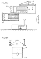
- the roller shown in FIG. 9 is in cross section together with a Rake (100) shown for removal.
- the rake (100) can take the form of a Have hook and behind to remove the test element (1) through the slot (42) the test element are performed. With a pulling movement of the rake, the test element can are pulled out of the groove (41) onto a base (101). From here the test element can be subjected to further process steps for carrying out an analysis become.
- FIGS. 11A to F show a system for making test elements available, which has a refill facility for magazines.
- the system according to FIG. 11 corresponds in terms of the function of the slide (31) and the roller (40), essentially the system shown in Figure 8.
- FIG. 11A A drawer (70) can be seen, which is pulled out and filled with a magazine (30) can be inserted into the system.
- the magazine is moved into a removal position adjacent to the roller (40) (similar to Figure 8).
- the system shown in FIG. 11A has a height movable lifting platform (80) into which a magazine can be inserted from the drawer can, for which purpose a separate device can be provided.
- the slide (31) it is advantageous possible to use the slide (31) to move the magazine.
- the Move the carriage (33) to the left so far that the slide (31) from the bottom into the magazine (30) located in the drawer (70) engages.
- the carriage (33) is now move in the direction of the roller (40), so that the slide (31) with its front End (31a) engages an edge of the magazine and pulls the magazine into the lifting platform, as shown in Figure 11B.
- the lift has a platform to hold the magazine (80) a bottom surface (81) through which the magazine prevents it from falling becomes.
- the bottom surface (81) has a recess in which the slide (31) traverse can be. If a magazine is fully inserted into the lift (80), do so can the removal of test elements analogous to the procedure described for Figure 8 respectively. It is also possible to replace the now empty drawer with a new one Fill magazine (30 ') as shown in Figure 11C.
- the lift moves (80) to a height at which the lower edge of the magazine (30) is above the upper edge of the Magazine (30 ') is located (see Figure 11D). Now one becomes part of the lift Mechanism activated that the magazine (30) out of the lift onto the magazine (30 ') moves.
- the lifting platform can preferably have a circumferential belt (82) possessed, which is driven by a motor (83). There is an ejection cam on the belt (84) attached, the magazine (30) as desired when moving the belt shifts.
- the magazine (30) can, for example, lie on the magazine (30 ') and falls in when the magazine (30 ') is pulled under it according to FIG. 11B the drawer.
- the system according to FIG. 11 preferably has that in FIG. 11F holding device shown as an example.
- FIG. 11F shows two rollers (90) arranged opposite one another, between which the Magazine (30) is pushed.
- the rollers (90) advantageously have rubber pads (91) or the like, so that when inserting the magazine (30) a close contact between the rollers and the magazine is produced, as a result, the rollers when inserted of the magazine and the magazine cannot fall uncontrollably.
- the empty magazine which is now in the drawer, can be used by the user removed and replaced with a fresh magazine if necessary. Consequently continuous operation is possible with this system, which is rarely an action of the user.
Landscapes
- Health & Medical Sciences (AREA)
- Life Sciences & Earth Sciences (AREA)
- Engineering & Computer Science (AREA)
- Physics & Mathematics (AREA)
- Biomedical Technology (AREA)
- Chemical & Material Sciences (AREA)
- Analytical Chemistry (AREA)
- Biochemistry (AREA)
- General Health & Medical Sciences (AREA)
- General Physics & Mathematics (AREA)
- Immunology (AREA)
- Pathology (AREA)
- Optics & Photonics (AREA)
- Biophysics (AREA)
- Hematology (AREA)
- Molecular Biology (AREA)
- Urology & Nephrology (AREA)
- Food Science & Technology (AREA)
- Medicinal Chemistry (AREA)
- Automatic Analysis And Handling Materials Therefor (AREA)
- Container, Conveyance, Adherence, Positioning, Of Wafer (AREA)
- Packaging Of Annular Or Rod-Shaped Articles, Wearing Apparel, Cassettes, Or The Like (AREA)
- Investigating Or Analysing Biological Materials (AREA)
- Testing Or Measuring Of Semiconductors Or The Like (AREA)
- Testing Of Individual Semiconductor Devices (AREA)
Description
- Entnahme eines Testelementes aus einer Entnahmeposition des Magazins (kann durch Herausschieben, Herausziehen oder eine Kombination beider Vorgänge erfolgen)
- Verschieben des in einer Ebene befindlichen Ensemble von Testelementen, so daß ein neues in die Entnahmeposition befördert wird
- Fig. 1A:
- Testelement in Aufsicht
- Fig. 1B:
- Seitenansicht eines Testelementes
- Fig. 2:
- Schnitt durch ein Magazin entlang einer Ebene von Testelementen
- Fig. 3:
- Schnitt durch ein Magazin entlang Schnittlinie A' in Figur 2
- Fig. 4:
- Schnitt durch ein Magazin entlang der Linie B' in Figur 2
- Fig. 5:
- Ausschnittsvergrößerung des Bereiches X in Figur 4
- Fig. 6:
- Stand der Technik (US-3,918,910)
- Fig. 7:
- Aus zusammengesteckten Rahmen aufgebautes Magazin
- Fig. 8:
- System zum Zurverfügungstellen von Testelementen
- Fig. 9:
- Walze mit Nut zur Aufnahme von Testelementen
- Fig. 10:
- System zur Entnahme von Testelementen aus der Walze
- Fig. 11:
- System zum Zurverfügungstellen von Testelementen mit Nachfülleinrichtungen
- (1)
- Testelement
- (2)
- Träger
- (3)
- Testzone
- (10a)
- linke Seitenfläche
- (10b)
- rechte Seitenfläche
- (11)
- Trockenmittelkammer
- (12)
- Vorderseite
- (13)
- Pfeil im Vorschubrichtung
- (14)
- Ausstoßschieber
- (15)
- Pfeil in Ausstoßrichtung
- (16a, 16b)
- Schlitze
- (17)
- Schieber
- (18a, 18b)
- Nutenpaar
- (20)
- einzelner Rahmen
- (21)
- Rand
- (22)
- Absatz
- (23)
- rechteckige Ausdehnung
- (24)
- Schlitz
- (30)
- Magazin
- (31)
- Schieber
- (31a)
- vorderes Ende des Schiebers
- (31b)
- hinteres Ende des Schiebers
- (32)
- Achse
- (33)
- Schlitten
- (34)
- Feder
- (40)
- Sensor
- (40)
- Walze
- (41)
- Nut
- (42)
- Schlitz
- (50)
- Gehäuse
- (60)
- Trockenmittel
- (70)
- Schublade
- (80)
- Hebebühne
- (81)
- Boden der Hebebühne
- (82)
- Riemen
- (83)
- Motor
- (84)
- Auswurfnocken
- (90)
- Rollen
- (91)
- Gummiauflage
- (100)
- Rechen
- (101)
- Unterlage
Claims (32)
- Magazin zur Bevorratung von Testelementen mit einer oder mehreren Testzonen, die nebeneinander auf einem rechteckigen Träger befestigt sind, wobei das Magazin mindestens ein Paar gegenüberliegender Führungsnuten aufweist, in die die Testelemente so eingeschoben sind, daß sie direkt nebeneinander liegen und Kanten benachbarter Träger aneinanderstoßen.
- Magazin gemäß Anspruch 1, mit zwei oder mehr Paaren gegenüberliegender Führungsnuten, wobei die Paare übereinander angeordnet sind.
- Magazin gemäß Anspruch 1 oder 2, das Wandungen aufweist, die das Magazin gegenüber dem Außenraum abschließen.
- Magazin gemäß Anspruch 2, bei dem die Führungsnuten in eine Seitenwand des Magazins integriert sind und das pro Paar von Führungsnuten eine Öffnung besitzt, die in einer Seitenwand angeordnet ist.
- Magazin gemäß Anspruch 4, bei dem die Öffnung einen rechteckigen Querschnitt besitzt, dessen Höhe um 10 bis 50 % größer ist als die maximale Höhe der Testelemente und dessen Breite um 10 bis 50 % größer ist als die Breite der Testelemente.
- Magazin gemäß Anspruch 4, bei dem das Magazin eine Stirnfläche besitzt, die im wesentlichen senkrecht zu den Seitenwänden verläuft.
- Magazin gemäß Anspruch 6, bei dem sich in der Stirnfläche entweder pro Paar von Nuten eine Öffnung befindet, die so angeordnet ist, daß Testelemente, die in den Nuten verschoben werden, durch die Öffnung aus dem Magazin austreten können oder die Stirnfläche offen ist.
- Magazin gemäß Anspruch 7, bei dem die Öffnung einen rechteckigen Querschnitt besitzt, dessen Breite um 10 bis 30 % größer ist als die maximale Höhe der Testelemente und dessen Länge um 0,5 bis 20 % größer ist als die Teststreifenlänge.
- Magazin gemäß Anspruch 3, beinhaltend mindestens eine Ausnehmung in einer Wandung, die parallel zu der Ebene von Testelementen verläuft.
- Magazin gemäß Anspruch 7, beinhaltend Federelemente, die die Testelemente innerhalb der Nut so verschieben, daß ein Testelement gegenüber der Öffnung zu liegen kommt und durch die Öffnung entnommen werden kann.
- Magazin gemäß Anspruch 1, das in seinem Inneren ein Trockenmittel enthält.
- Magazin gemäß Anspruch 1, bei dem die Vorderseite des Magazins zumindest teilweise durch eine Siegelfolie verschlossen ist.
- Magazin gemäß Anspruch 1, bei dem die Vorderseite zumindest teilweise durch eine Siegelfolie und die Rückseite durch eine Trockenmittelkammer verschlossen ist.
- Magazin gemäß Anspruch 1 oder 13, das aus den folgenden Elementen aufgebaut ist:zwei Seitenwände mit integrierten Führungsnuten,zwei Wände, die die Seitenwände so miteinander verbinden, daß ein Quader entstehteine Trockenmittelkammer, die an der Rückseite des Magazins angeordnet ist.
- Magazin gemäß Anspruch 14, bei dem die offene Stirnfläche des Quaders zumindest teilweise durch eine Siegelfolie verschlossen ist.
- Magazin gemäß Anspruch 14, bei dem die genannten Teile als ein zusammenhängendes Spritzgußteil hergestellt werden und über Filmscharniere miteinander verbunden sind.
- System zum Zuverfügungstellen von Testelementen beinhaltendein Magazin mit mindestens zwei gegenüberliegenden Führungsnuten, in die Testelemente so eingeschoben sind, daß sie in einer Fläche direkt nebeneinander liegen und Kanten benachbarter Testelemente aneinanderstoßen,einen Schieber, der an einem Ende der durch die Testelemente gebildeten Lage angreift und die Testelemente entlang der Nuten in Richtung auf das gegenüberliegende Ende der Lage verschiebt.
- System gemäß Anspruch 17, bei dem das Magazin eine Wand mit mindestens einer Ausnehmung besitzt, durch die der Schieber in das Magazin eingeführt wird.
- System gemäß Anspruch 17, bei dem der Schieber durch eine Antriebseinheit angetrieben wird.
- System gemäß Anspruch 19, bei dem die Antriebseinheit den Schieber in eine Raumrichtung um ein Wegstück abhängig von der Breite der Testelemente verschiebt.
- System gemäß Anspruch 19 oder 20, bei dem die Antriebseinheit die Eindringtiefe des Schiebers in das Magazin steuert
- System gemäß Anspruch 17, mit einem zweiten Schieber, der ein Testelement, das sich in einer Entnahmeposition befindet, durch Verschiebung in Längsrichtung des Testelements aus dem Magazin herausbefördert.
- System gemäß Anspruch 22, bei dem das Magazin in der Entnahmeposition eine erste und eine zweite Öffnung aufweist und der zweite Schieber in die erste Öffnung eindringt und das in der Entnahmeposition befindliche Testelement durch die zweite Öffnung herausschiebt.
- System zum Zurverfügungstellen von Testelementen gemäß Anspruch 17 mit einer um ihre Achse drehbar gelagerten Walze, in der sich mindestens eine Nut zur Aufnahme eines Testelementes befindet.
- System gemäß Anspruch 24, bei dem die Walze gegenüber dem Magazin so angeordnet ist, daß ein Testelement, das durch den Schieber aus dem Magazin herausgeschoben wird, in die mindestens eine Nut der Walze eingeschoben wird.
- System gemäß Anspruch 24 oder 25, bei dem das Magazin in einem im wesentlichen feuchtigkeitsdichten Gehäuse mit einer Ausnehmung angeordnet ist und die Ausnehmung durch die Walze derart verschlossen ist, daß sich die mindestens eine Nut in einer ersten Position der Walze zur Aufnahme eines Testelementes innerhalb des Gehäuses befindet und durch Drehung der Walze um ihre Achse aus dem Gehäuse heraustransportiert werden kann.
- System gemäß Anspruch 26, bei dem das Gehäuse einen Schutzteil besitzt, der so gegenüber einem Teil der Außenumfangsfläche der Walze angeordnet ist, daß zwischen Walze und Schutzteil ein Spalt gebildet wird, der es ermöglicht ein Testelement, das sich in der mindestens einen Nut befindet, und über die Außenkontur der Walze hinausragt, durch Drehen der Walze durch ihn hindurchzuführen und der eine Kriechstrecke bildet, durch die ein Eindringen von Feuchtigkeit in das Gehäuse reduziert wird.
- System gemäß einem der Ansprüche 24 bis 27, bei dem die Walze mindestens einen Einschnitt besitzt, der im wesentlichen senkrecht zur Längsachse der Walze im Bereich der mindestens einen Nut verläuft, und der tiefer als die mindestens eine Nut ist, so daß sich im Einschnitt hinter der Nut ein Bereich zum Hintergreifen eines in der Nut befindlichen Testelementes ergibt.
- System gemäß Anspruch 28 mit einem Rechen, der außerhalb des Gehäuses angeordnet ist und in eine erste Position gebracht werden kann, in der er in den Einschnitt eingreift und ein in der Nut befindliches Testelement hintergreift und der zur Entnahme des Testelementes aus der Nut in eine zweite Position verfahren werden kann.
- System gemäß Anspruch 17, bei dem der Schieber über eine Achse an einem Schlitten befestigt ist, zu dem er sich in seiner Ruhelage in einer Winkelposition befindet, aus der er herausgedreht wird, wenn der Schlitten verschoben wird und der Schieber durch die Lage von Testelementen einen Widerstand erfährt.
- System gemäß Anspruch 30 mit einer Detektionseinheit, die ein Herausdrehen des Schiebers aus seiner Ruhelage detektiert.
- System gemäß Anspruch 17, das eine Aufnahmeposition für ein weiteres Magazin sowie einen Hebemechanismus zum Herausheben eines zumindest teilweise entleerten Magazins aus einer Position zur Entnahme von Testelementen besitzt.
Applications Claiming Priority (3)
| Application Number | Priority Date | Filing Date | Title |
|---|---|---|---|
| DE19715031 | 1997-04-11 | ||
| DE19715031A DE19715031A1 (de) | 1997-04-11 | 1997-04-11 | Magazin zur Bevorratung von Testelementen |
| PCT/EP1998/002065 WO1998047007A1 (de) | 1997-04-11 | 1998-04-09 | Magazin zur bevorratung von testelementen |
Publications (2)
| Publication Number | Publication Date |
|---|---|
| EP0974061A1 EP0974061A1 (de) | 2000-01-26 |
| EP0974061B1 true EP0974061B1 (de) | 2002-01-02 |
Family
ID=7826144
Family Applications (1)
| Application Number | Title | Priority Date | Filing Date |
|---|---|---|---|
| EP98919244A Expired - Lifetime EP0974061B1 (de) | 1997-04-11 | 1998-04-09 | Magazin zur bevorratung von testelementen |
Country Status (7)
| Country | Link |
|---|---|
| US (2) | US6534017B1 (de) |
| EP (1) | EP0974061B1 (de) |
| JP (1) | JP3455548B2 (de) |
| AT (1) | ATE211553T1 (de) |
| DE (2) | DE19715031A1 (de) |
| ES (1) | ES2171020T3 (de) |
| WO (1) | WO1998047007A1 (de) |
Families Citing this family (79)
| Publication number | Priority date | Publication date | Assignee | Title |
|---|---|---|---|---|
| DE19715031A1 (de) * | 1997-04-11 | 1998-10-15 | Boehringer Mannheim Gmbh | Magazin zur Bevorratung von Testelementen |
| US7416699B2 (en) | 1998-08-14 | 2008-08-26 | The Board Of Trustees Of The Leland Stanford Junior University | Carbon nanotube devices |
| US7138089B2 (en) | 2000-07-20 | 2006-11-21 | Hypoguard Limited | Test device for analyzing blood glucose or other analytes in bodily fluids |
| US6827899B2 (en) | 2000-08-30 | 2004-12-07 | Hypoguard Limited | Test device |
| US7063234B2 (en) * | 2000-12-29 | 2006-06-20 | Csp Technologies, Inc. | Meter strip dispenser assembly |
| SE522297C2 (sv) * | 2001-05-17 | 2004-01-27 | Biodisk Ab | Förfarande och anordning för anbringande av tunna föremål samt användning av förpackning för de tunna föremålen |
| WO2003034076A1 (en) * | 2001-10-19 | 2003-04-24 | Monogen, Inc. | Article handling system and method |
| US6908008B2 (en) | 2001-12-21 | 2005-06-21 | Lifescan, Inc. | Test device with means for storing and dispensing diagnostic strips |
| US6872358B2 (en) * | 2002-01-16 | 2005-03-29 | Lifescan, Inc. | Test strip dispenser |
| US7172728B2 (en) | 2002-04-02 | 2007-02-06 | Lifescan, Inc. | Test strip containers and methods of using the same |
| US6881578B2 (en) | 2002-04-02 | 2005-04-19 | Lifescan, Inc. | Analyte concentration determination meters and methods of using the same |
| US20030195435A1 (en) * | 2002-04-12 | 2003-10-16 | Williams Arthur G. | Method and apparatus for collecting and transporting capillary blood samples for diagnostic and research evaluation |
| CN101173920B (zh) * | 2002-04-19 | 2012-04-18 | 松下电器产业株式会社 | 生物传感器盒及生物传感器分给装置 |
| CN100567988C (zh) * | 2002-07-19 | 2009-12-09 | 爱科来株式会社 | 分析装置的分析物搬送装置 |
| US7225008B1 (en) | 2003-05-21 | 2007-05-29 | Isense Corporation | Multiple use analyte sensing assembly |
| US7862519B1 (en) | 2003-05-21 | 2011-01-04 | Isense Corporation | Easy-to-use multi-use body fluid specimen collection and analyte sensing assembly |
| US7753457B2 (en) * | 2003-06-12 | 2010-07-13 | Cytyc Corporation | Apparatus for removably retaining a slide within a cassette |
| US7617932B2 (en) * | 2003-09-19 | 2009-11-17 | Diabetes Diagnostics, Inc. | Medical device package, kit and associated methods |
| US8147426B2 (en) | 2003-12-31 | 2012-04-03 | Nipro Diagnostics, Inc. | Integrated diagnostic test system |
| US8394328B2 (en) * | 2003-12-31 | 2013-03-12 | Nipro Diagnostics, Inc. | Test strip container with integrated meter having strip coding capability |
| US9012232B2 (en) * | 2005-07-15 | 2015-04-21 | Nipro Diagnostics, Inc. | Diagnostic strip coding system and related methods of use |
| US8394337B2 (en) | 2003-12-31 | 2013-03-12 | Nipro Diagnostics, Inc. | Test strip container with integrated meter |
| DE102004010529B4 (de) * | 2004-03-04 | 2007-09-06 | Roche Diagnostics Gmbh | Analysehandgerät |
| USD506832S1 (en) | 2004-06-02 | 2005-06-28 | Home Diagnostics, Inc. | Meter for an integrated diagnostic test system |
| USD507657S1 (en) | 2004-06-02 | 2005-07-19 | Home Diagnostics, Inc. | Meter for an integrated diagnostic test system |
| CN101065672A (zh) * | 2004-09-30 | 2007-10-31 | 生命扫描苏格兰有限公司 | 盒匣组件驱动装置和方法 |
| CA2584766A1 (en) * | 2004-10-20 | 2006-04-27 | Jeffery S. Reynolds | Cartridge for containing and dispensing test sensors |
| RU2390023C2 (ru) | 2004-10-21 | 2010-05-20 | БАЙЕР ХЕЛТКЭА ЭлЭлСи | Диспенсер датчиков и механизм для извлечения датчика |
| CN102879525B (zh) * | 2004-12-13 | 2014-12-24 | 拜尔保健有限公司 | 独立式测试传感器 |
| JP2006170974A (ja) | 2004-12-15 | 2006-06-29 | F Hoffmann-La Roche Ag | 分析試験エレメント上での液体試料の分析用分析システム |
| DE102004060322A1 (de) | 2004-12-15 | 2006-06-22 | Roche Diagnostics Gmbh | Analysesystem mit einem elektrischen Anschlusssystem für ein Testelement |
| WO2006066123A1 (en) * | 2004-12-17 | 2006-06-22 | Bayer Healthcare Llc | Disposable test sensor cartridge |
| TW200630602A (en) * | 2005-01-14 | 2006-09-01 | Bayer Healthcare Llc | Test sensor cartridges and sensor-dispensing instruments |
| USD561904S1 (en) | 2005-01-31 | 2008-02-12 | Home Diagnostics, Inc. | Meter for an integrated diagnostic test system |
| EP1949099B1 (de) * | 2005-03-22 | 2010-06-02 | Bayer Healthcare, LLC | Kartusche mit rad zum öffnungsverschluss |
| EP1712910A1 (de) * | 2005-04-12 | 2006-10-18 | F.Hoffmann-La Roche Ag | Analysegerät zur Analyse einer Probenflüssigkeit mittels eines Testelements |
| US8545755B2 (en) * | 2005-04-25 | 2013-10-01 | Bayer Healthcare Llc | Sensor release mechanism for a test meter |
| EP1726951A1 (de) * | 2005-05-24 | 2006-11-29 | F. Hoffman-la Roche AG | Magazine zur Aufnahme von Testelementen |
| EP1726950A1 (de) * | 2005-05-24 | 2006-11-29 | F. Hoffmann-La Roche Ag | Magazin zur Aufnahme von Testelementen |
| US20060275890A1 (en) * | 2005-06-06 | 2006-12-07 | Home Diagnostics, Inc. | Method of manufacturing a disposable diagnostic meter |
| ATE454623T1 (de) * | 2005-06-14 | 2010-01-15 | Hoffmann La Roche | Körperflüssigkeit-analysevorrichtung mit einem testfelder aufweisenden testband |
| US8999125B2 (en) | 2005-07-15 | 2015-04-07 | Nipro Diagnostics, Inc. | Embedded strip lot autocalibration |
| US7955856B2 (en) * | 2005-07-15 | 2011-06-07 | Nipro Diagnostics, Inc. | Method of making a diagnostic test strip having a coding system |
| US20070065338A1 (en) * | 2005-09-06 | 2007-03-22 | Jerry Schindler | Testing strip and dispenser |
| DE102006001881A1 (de) | 2006-01-13 | 2007-07-19 | Roche Diagnostics Gmbh | Verpackungskassette für Reagenzienträger |
| US7708702B2 (en) * | 2006-01-26 | 2010-05-04 | Roche Diagnostics Operations, Inc. | Stack magazine system |
| US11559810B2 (en) | 2006-03-13 | 2023-01-24 | Trividia Health, Inc. | Method and apparatus for coding diagnostic meters |
| US8388906B2 (en) * | 2006-03-13 | 2013-03-05 | Nipro Diagnostics, Inc. | Apparatus for dispensing test strips |
| US8940246B2 (en) | 2006-03-13 | 2015-01-27 | Nipro Diagnostics, Inc. | Method and apparatus for coding diagnostic meters |
| US8388905B2 (en) * | 2006-03-13 | 2013-03-05 | Nipro Diagnostics, Inc. | Method and apparatus for coding diagnostic meters |
| PL1873521T3 (pl) * | 2006-06-27 | 2012-02-29 | Hoffmann La Roche | Diagnostyczna kaseta z taśmą |
| US20080020452A1 (en) * | 2006-07-18 | 2008-01-24 | Natasha Popovich | Diagnostic strip coding system with conductive layers |
| US20080217353A1 (en) * | 2007-03-06 | 2008-09-11 | Michael John Newman | Method of Dispensing A Test Strip |
| US9052305B2 (en) | 2007-03-06 | 2015-06-09 | Lifescan, Inc. | Test strip dispenser |
| JP2010521666A (ja) * | 2007-03-12 | 2010-06-24 | バイエル・ヘルスケア・エルエルシー | センサ操作のいらないシングルセンサメータシステム及びそれを用いた方法 |
| EP1970006A1 (de) | 2007-03-14 | 2008-09-17 | Roche Diagnostics GmbH | Analysesystem zur Bestimmung eines Analyten in einer Körperflüssigkeit und disposibles integriertes Probengewinnungs- und Analyseelement |
| US20080286149A1 (en) * | 2007-05-14 | 2008-11-20 | Roe Steven N | Bodily fluid sampling with test strips hinged on a tape |
| EP2028488B1 (de) * | 2007-08-02 | 2015-02-25 | F. Hoffmann-La Roche AG | Transfereinheit für Testelemente |
| US7661325B2 (en) * | 2007-12-13 | 2010-02-16 | Sousei Electronics Corporation | Test piece magazine, magazine holder, and test piece attachment apparatus |
| US8166872B2 (en) * | 2008-03-12 | 2012-05-01 | Whirlpool Corporation | Modified atmosphere for food preservation |
| KR100926154B1 (ko) * | 2008-05-08 | 2009-11-10 | 주식회사 메카시스 | 스트립 공급장치 |
| WO2009152183A2 (en) * | 2008-06-09 | 2009-12-17 | Biomicro, Inc. | System and method for hybridization slide processing |
| US8622231B2 (en) * | 2009-09-09 | 2014-01-07 | Roche Diagnostics Operations, Inc. | Storage containers for test elements |
| US8728395B2 (en) * | 2010-01-28 | 2014-05-20 | Hitachi High-Technologies Corporation | Automatic analyzer |
| JP5340975B2 (ja) * | 2010-01-29 | 2013-11-13 | 株式会社日立ハイテクノロジーズ | 自動分析装置 |
| US8550295B2 (en) | 2010-02-22 | 2013-10-08 | Roche Diagnostics Operations, Inc. | Container for dispensing a single test strip |
| US20110272420A1 (en) * | 2010-05-05 | 2011-11-10 | Applied Materials, Inc. | Enclosed vertical rack for storing and transporting large substrates |
| US8535618B1 (en) | 2010-09-08 | 2013-09-17 | Robert L. Werner | Test strip dispenser |
| US8475733B2 (en) | 2011-08-04 | 2013-07-02 | Cilag Gmbh International | Hand-held test meter and analytical test strip cartridge assembly with desiccant vial |
| WO2013059483A1 (en) | 2011-10-20 | 2013-04-25 | Jabil Circuit, Inc. | Cartridge and metering device for fluid- testing strips |
| WO2013096268A1 (en) | 2011-12-20 | 2013-06-27 | Bayer Heal Thcare Llc | Linear, cartridge-based glucose measurement system |
| US9097700B2 (en) | 2011-12-29 | 2015-08-04 | Bayer Healthcare Llc | Glucose measurement system with high-capacity cartridge and capability of more frequent replenishment |
| US9383333B2 (en) | 2012-05-31 | 2016-07-05 | Ascensia Diabetes Care Holdings Ag | Replaceable multistrip cartridge and biosensor meter |
| US9204829B2 (en) | 2012-05-31 | 2015-12-08 | Bayer Healthcare Llc | Multistrip cartridge |
| US10533949B2 (en) | 2013-03-12 | 2020-01-14 | Ascensia Diabetes Care Holdings Ag | Test strip meter with a mechanism for pushing the test strip against an optical reader |
| US20150160186A1 (en) * | 2013-12-09 | 2015-06-11 | Steven Garner-Richards | Diabetic Testing Supply Dispenser |
| CN104734867B (zh) * | 2013-12-19 | 2019-05-03 | 中兴通讯股份有限公司 | 网络业务节点故障处理方法、装置及系统 |
| DE102019134394A1 (de) * | 2019-12-13 | 2021-06-17 | Hamilton Storage Gmbh | Labor-Speicherschrank mit Rotationskörper in einer Transferschleuse |
| CN116280656B (zh) * | 2022-11-17 | 2025-05-27 | 天翼云科技有限公司 | 一种智能网卡插取检测设备 |
Family Cites Families (21)
| Publication number | Priority date | Publication date | Assignee | Title |
|---|---|---|---|---|
| FR1438418A (fr) | 1965-03-26 | 1966-05-13 | Ibm France | étui pour documents codés et système de contrôle automatique en comportant application |
| US3853711A (en) * | 1970-06-22 | 1974-12-10 | Biotec Ab | Installation for automation of microbiological work techniques |
| DE2118455B1 (de) | 1971-04-16 | 1972-09-21 | Boehringer Mannheim Gmbh | Teststreifen |
| US3918910A (en) | 1973-07-31 | 1975-11-11 | Olympus Optical Co | System for detecting the particular chemical constituent of a fluid |
| US4142863A (en) | 1978-06-05 | 1979-03-06 | Eastman Kodak Company | Article container for dispensing reagent slides |
| US4218421A (en) * | 1978-08-18 | 1980-08-19 | Honeywell Inc. | Disposable container for a continuous band of test strips |
| CA1185280A (en) | 1981-05-13 | 1985-04-09 | Frank Wogoman | Test device handling system |
| US4518565A (en) | 1983-06-06 | 1985-05-21 | Miles Laboratories, Inc. | Reagent test device holder |
| DE3786087T2 (de) | 1986-02-07 | 1993-09-16 | Fuji Photo Film Co Ltd | Geraet fuer chemische analysen. |
| DE3625697A1 (de) | 1986-07-30 | 1988-02-11 | Hoechst Ag | Vorrichtung zum vereinzeln von teststreifen |
| US5154889A (en) | 1986-08-07 | 1992-10-13 | Fuji Photo Film Co., Ltd. | Chemical analysis apparatus |
| JPS6361956A (ja) | 1986-09-03 | 1988-03-18 | Fuji Photo Film Co Ltd | 化学分析装置 |
| DE3715938A1 (de) * | 1987-05-13 | 1988-11-24 | Boehringer Mannheim Gmbh | Behaelter fuer teststreifen |
| US4911344A (en) | 1988-03-23 | 1990-03-27 | Tek-Aids Inc. | Strip dispenser box |
| JP2601075B2 (ja) * | 1991-10-21 | 1997-04-16 | 株式会社日立製作所 | 試験片を用いる分析方法および分析装置 |
| DE4204245A1 (de) * | 1992-02-13 | 1993-08-19 | Boehringer Mannheim Gmbh | Vorrichtung zum lagerichtigen zufuehren von teststreifen zu einer analyseeinrichtung |
| DE4313253A1 (de) | 1993-04-23 | 1994-10-27 | Boehringer Mannheim Gmbh | System zur Analyse von Inhaltsstoffen flüssiger Proben |
| US5536472A (en) | 1993-11-22 | 1996-07-16 | Fuji Photo Film Co., Ltd. | Chemical analysis element cartridge |
| JP3368985B2 (ja) * | 1994-05-10 | 2003-01-20 | バイエルコーポレーション | 自動供給装置 |
| DE4425439A1 (de) * | 1994-07-19 | 1996-01-25 | Boehringer Mannheim Gmbh | Teststreifenauswertegerät mit einer Transporteinheit für Teststreifen |
| DE19715031A1 (de) * | 1997-04-11 | 1998-10-15 | Boehringer Mannheim Gmbh | Magazin zur Bevorratung von Testelementen |
-
1997
- 1997-04-11 DE DE19715031A patent/DE19715031A1/de not_active Withdrawn
-
1998
- 1998-04-09 AT AT98919244T patent/ATE211553T1/de not_active IP Right Cessation
- 1998-04-09 WO PCT/EP1998/002065 patent/WO1998047007A1/de not_active Ceased
- 1998-04-09 ES ES98919244T patent/ES2171020T3/es not_active Expired - Lifetime
- 1998-04-09 JP JP54345498A patent/JP3455548B2/ja not_active Expired - Fee Related
- 1998-04-09 DE DE59802797T patent/DE59802797D1/de not_active Expired - Lifetime
- 1998-04-09 US US09/402,315 patent/US6534017B1/en not_active Expired - Lifetime
- 1998-04-09 EP EP98919244A patent/EP0974061B1/de not_active Expired - Lifetime
-
2002
- 2002-07-30 US US10/209,402 patent/US6682704B2/en not_active Expired - Lifetime
Also Published As
| Publication number | Publication date |
|---|---|
| ES2171020T3 (es) | 2002-08-16 |
| JP3455548B2 (ja) | 2003-10-14 |
| EP0974061A1 (de) | 2000-01-26 |
| US6534017B1 (en) | 2003-03-18 |
| DE59802797D1 (de) | 2002-02-28 |
| DE19715031A1 (de) | 1998-10-15 |
| WO1998047007A1 (de) | 1998-10-22 |
| US20030002387A1 (en) | 2003-01-02 |
| JP2001523333A (ja) | 2001-11-20 |
| ATE211553T1 (de) | 2002-01-15 |
| US6682704B2 (en) | 2004-01-27 |
Similar Documents
| Publication | Publication Date | Title |
|---|---|---|
| EP0974061A1 (de) | Magazin zur bevorratung von testelementen | |
| DE3220606C2 (de) | Einrichtung zum automatischen Be- und Entladen von Röntgenfilmkassetten | |
| DE1900275C3 (de) | Automatischer chemischer Analyseapparat | |
| EP0542793B1 (de) | Anordnung zum lagern, transportieren und einschleusen von substraten | |
| DE3610659C1 (de) | Roentgenblattfilmkassettenent- und -beladegeraet | |
| DE19728984A1 (de) | Tintenpatrone und Lademechanismus für die Tintenpatrone | |
| DE2248408B1 (de) | Behaelter zur aufnahme einer kassette mit einem bandfoermigen aufzeichnungstraeger | |
| DE2452798B2 (de) | Kassette zur Verwendung als Zufuhr-, Aufbewahrungs- und Ablagemagazin für im wesentlichen rechteckf örmige Datenträger | |
| EP0102577B1 (de) | Vorrichtung zum Be- und Entladen von Röntgen-Filmkassetten | |
| DE2711853C3 (de) | Einrichtung zur Handhabung und Bereitstellung von Einmalküvetten | |
| DE19603464A1 (de) | Vorrichtung zum Beladen von Aufnahmebehältern für langgestreckte Gegenstände | |
| DE69217204T2 (de) | Bandkassettenzufuhreinheit für automatischen Vorrichtungen | |
| DE3430943A1 (de) | Papierzufuehrungskassette | |
| DE3931715C2 (de) | Plattenmagazin für Plattenwechsler | |
| DE3147034A1 (de) | Verfahren und vorrichtung zum abtrennen von blechen von einem stapel | |
| DE3878762T2 (de) | Verpackungsband. | |
| DE69027445T2 (de) | Behälter für gefaltete blätter | |
| DE2522936C2 (de) | Testscheiben-Abgabevorrichtung | |
| DE3410687A1 (de) | Methode und vorrichtung zum automatischen bzw. nicht automatischen einrahmen von filmstreifenabschnitten vorprogrammierter laenge, auf rahmen, welche sich auf einer seite elastisch und mechanisch oeffnen und daraus erlangene einzelfilme | |
| DE69504837T2 (de) | Eine magazinanordnung | |
| DE4316363A1 (de) | Vorrichtung zum Beschicken eines Behälters mit gestapelten Zellstoffprodukten, insbesondere Wattepads | |
| DE3828124A1 (de) | Automatischer kassettenwechsler | |
| DE3872180T2 (de) | Anordnung zum verpacken. | |
| DE2545771C2 (de) | Behälter zur Aufbewahrung einer Magnetbandkassette | |
| DE2747623A1 (de) | Vorratsmagazin mit einer vorrichtung zur entnahme jeweils eines einzelnen filmblattes |
Legal Events
| Date | Code | Title | Description |
|---|---|---|---|
| PUAI | Public reference made under article 153(3) epc to a published international application that has entered the european phase |
Free format text: ORIGINAL CODE: 0009012 |
|
| 17P | Request for examination filed |
Effective date: 19991111 |
|
| AK | Designated contracting states |
Kind code of ref document: A1 Designated state(s): AT CH DE ES FR GB IT LI PT |
|
| RAP1 | Party data changed (applicant data changed or rights of an application transferred) |
Owner name: ROCHE DIAGNOSTICS GMBH |
|
| GRAG | Despatch of communication of intention to grant |
Free format text: ORIGINAL CODE: EPIDOS AGRA |
|
| 17Q | First examination report despatched |
Effective date: 20010313 |
|
| GRAG | Despatch of communication of intention to grant |
Free format text: ORIGINAL CODE: EPIDOS AGRA |
|
| GRAH | Despatch of communication of intention to grant a patent |
Free format text: ORIGINAL CODE: EPIDOS IGRA |
|
| GRAH | Despatch of communication of intention to grant a patent |
Free format text: ORIGINAL CODE: EPIDOS IGRA |
|
| GRAA | (expected) grant |
Free format text: ORIGINAL CODE: 0009210 |
|
| REG | Reference to a national code |
Ref country code: GB Ref legal event code: IF02 |
|
| AK | Designated contracting states |
Kind code of ref document: B1 Designated state(s): AT CH DE ES FR GB IT LI PT |
|
| PG25 | Lapsed in a contracting state [announced via postgrant information from national office to epo] |
Ref country code: GB Free format text: LAPSE BECAUSE OF FAILURE TO SUBMIT A TRANSLATION OF THE DESCRIPTION OR TO PAY THE FEE WITHIN THE PRESCRIBED TIME-LIMIT Effective date: 20020102 |
|
| REF | Corresponds to: |
Ref document number: 211553 Country of ref document: AT Date of ref document: 20020115 Kind code of ref document: T |
|
| REG | Reference to a national code |
Ref country code: CH Ref legal event code: EP |
|
| REF | Corresponds to: |
Ref document number: 59802797 Country of ref document: DE Date of ref document: 20020228 |
|
| PG25 | Lapsed in a contracting state [announced via postgrant information from national office to epo] |
Ref country code: PT Free format text: LAPSE BECAUSE OF FAILURE TO SUBMIT A TRANSLATION OF THE DESCRIPTION OR TO PAY THE FEE WITHIN THE PRESCRIBED TIME-LIMIT Effective date: 20020402 |
|
| PG25 | Lapsed in a contracting state [announced via postgrant information from national office to epo] |
Ref country code: AT Free format text: LAPSE BECAUSE OF NON-PAYMENT OF DUE FEES Effective date: 20020409 |
|
| PG25 | Lapsed in a contracting state [announced via postgrant information from national office to epo] |
Ref country code: LI Free format text: LAPSE BECAUSE OF NON-PAYMENT OF DUE FEES Effective date: 20020430 Ref country code: CH Free format text: LAPSE BECAUSE OF NON-PAYMENT OF DUE FEES Effective date: 20020430 |
|
| ET | Fr: translation filed |
Owner name: ROCHE DIAGNOSTICS CORPORATION |
|
| REG | Reference to a national code |
Ref country code: ES Ref legal event code: FG2A Ref document number: 2171020 Country of ref document: ES Kind code of ref document: T3 |
|
| PLBE | No opposition filed within time limit |
Free format text: ORIGINAL CODE: 0009261 |
|
| STAA | Information on the status of an ep patent application or granted ep patent |
Free format text: STATUS: NO OPPOSITION FILED WITHIN TIME LIMIT |
|
| REG | Reference to a national code |
Ref country code: CH Ref legal event code: PL |
|
| 26N | No opposition filed | ||
| REG | Reference to a national code |
Ref country code: FR Ref legal event code: PLFP Year of fee payment: 19 |
|
| PGFP | Annual fee paid to national office [announced via postgrant information from national office to epo] |
Ref country code: FR Payment date: 20160331 Year of fee payment: 19 |
|
| PGFP | Annual fee paid to national office [announced via postgrant information from national office to epo] |
Ref country code: ES Payment date: 20160411 Year of fee payment: 19 Ref country code: DE Payment date: 20160414 Year of fee payment: 19 |
|
| PGFP | Annual fee paid to national office [announced via postgrant information from national office to epo] |
Ref country code: IT Payment date: 20160414 Year of fee payment: 19 |
|
| REG | Reference to a national code |
Ref country code: DE Ref legal event code: R119 Ref document number: 59802797 Country of ref document: DE |
|
| REG | Reference to a national code |
Ref country code: FR Ref legal event code: ST Effective date: 20171229 |
|
| PG25 | Lapsed in a contracting state [announced via postgrant information from national office to epo] |
Ref country code: FR Free format text: LAPSE BECAUSE OF NON-PAYMENT OF DUE FEES Effective date: 20170502 Ref country code: DE Free format text: LAPSE BECAUSE OF NON-PAYMENT OF DUE FEES Effective date: 20171103 |
|
| PG25 | Lapsed in a contracting state [announced via postgrant information from national office to epo] |
Ref country code: IT Free format text: LAPSE BECAUSE OF NON-PAYMENT OF DUE FEES Effective date: 20170409 |
|
| REG | Reference to a national code |
Ref country code: ES Ref legal event code: FD2A Effective date: 20180625 |
|
| PG25 | Lapsed in a contracting state [announced via postgrant information from national office to epo] |
Ref country code: ES Free format text: LAPSE BECAUSE OF NON-PAYMENT OF DUE FEES Effective date: 20170410 |