EP0973631B1 - Handhabungseinrichtung - Google Patents
Handhabungseinrichtung Download PDFInfo
- Publication number
- EP0973631B1 EP0973631B1 EP97951176A EP97951176A EP0973631B1 EP 0973631 B1 EP0973631 B1 EP 0973631B1 EP 97951176 A EP97951176 A EP 97951176A EP 97951176 A EP97951176 A EP 97951176A EP 0973631 B1 EP0973631 B1 EP 0973631B1
- Authority
- EP
- European Patent Office
- Prior art keywords
- coupling element
- handling device
- module
- modules
- snap
- Prior art date
- Legal status (The legal status is an assumption and is not a legal conclusion. Google has not performed a legal analysis and makes no representation as to the accuracy of the status listed.)
- Expired - Lifetime
Links
Images



Classifications
-
- B—PERFORMING OPERATIONS; TRANSPORTING
- B25—HAND TOOLS; PORTABLE POWER-DRIVEN TOOLS; MANIPULATORS
- B25J—MANIPULATORS; CHAMBERS PROVIDED WITH MANIPULATION DEVICES
- B25J9/00—Program-controlled manipulators
- B25J9/08—Program-controlled manipulators characterised by modular constructions
Definitions
- the invention relates to a handling device with several Handling modules, such as gripping, lifting or swivel modules, with the features of the preamble of claim 1.
- a such device is known from FR-A-2 657 286.
- Such a handling device usually has one Gripping module with a ansich arbitrary gripper, in particular Parallel gripper, angular gripper, etc. on, with the arbitrary Components or workpieces gripped and by interaction with one the gripping module controlling further module in the widest Senses are handled, so gripped, lifted off, translationally shifted, pivoted and / or in any Be deposited again.
- the workpiece facing Module may also be, for example, an intake module act.
- the individual modules have since been connected by screwing individual components together.
- a connection plate of a lifting module that can be raised and lowered relative to a housing body to a housing of a pivoting module.
- the swivel module can then be moved translationally by the lifting movement of the lifting module.
- the swivel module in turn has a pivotable with respect to a housing body connection plate, which can be screwed to a housing body of a gripping module.
- a handling device constructed in this way is thus able to turn the workpiece-facing gripping module about an axis and to translate it in the stroke direction of the lifting module. It is understood that a variety of handling devices can be produced by different design and combination of handling modules.
- the present invention is therefore based on the object a handling device of the type mentioned according to the invention To improve so that the individual handling modules easier can be connected or detached from each other.
- This task is at a handling device solved with the features of claim 1.
- EP-A-0 743 143 are used for connecting modules to the Modules rotatable flange parts provided with each other pluggable and spring-loaded clamping lever are townbarer. Drive and gearless coupling elements, as the intermediate components to the respective modules to be joined together are not disclosed. The same is taught by EP-A-0 477 725.
- the connecting device forms a plug-in mechanism, so that the coupling element in Mounting direction is pluggable, causing the snapping, latching and interdependent connection comes about. This proves prove to be particularly advantageous because the different ones Handling modules can be mounted very space-saving.
- the latching hooks are on the coupling element provided, which is preferably a plate-shaped, made of plastic injection molded part is. They then extend in opposite directions Directions towards the modules to be connected.
- a coupling element is first on one of the modules attached, and this is followed by this Module together with the coupling element to another module infected.
- a particularly stable backlash-free mounting of the modules together if the mentioned snap hooks are strip-shaped and substantially over the entire Width of the coupling element extend.
- the locking hook can but also be divided to the force needed to deflect to reduce. In this way, a certain compliance can be the latching hook and thus a desired installation force be set.
- the rotation can be in a particularly simple and therefore advantageousously, at least one in the mounting direction or plug-in direction extended projection and one in corresponding recess provided in which the Projection intervenes, be formed.
- Figure 1 shows a handling device of several Handling modules, namely a lifting module 2, a Swivel module 4 and a gripping module 6, wherein the lifting module 2 and the swivel module 4 via a connecting device 8 and the Swivel module 4 and the gripping module 6 via a Connecting device 10 are releasably connected together.
- the connecting devices 8, 10 include an even closer to descriptive plate-shaped coupling element 12, 14, wherein it is an injection-molded plastic part.
- the respective coupling element 12, 14 is snapping, latching and grasping at the two modules that connects it, assembled.
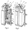
- the lifting module 2 comprises a housing body 16 in which three cylindrical Recesses 18 for receiving one guide rod 20th are formed. At the free end of each one off the housing body 16 projecting guide rod 20 is a Screwed connection plate 22.
- an in Lifting direction extended cylinder space 24 formed in which a Lifting piston 26 is movable in the stroke direction.
- the reciprocating piston 26 is via a piston rod 28 with the connection plate 22 via a connected screwed into its front side screw 30.
- the a pressure medium connection 36 or 38 outside the Housing body 16 leads.
- the pivot module 4 in detail shown. It comprises a housing body 40 with the Figure 4 apparent pressure fluid connections 42, in two Cylinder rooms open, in each of which a piston back and forth is herverschiebbar. Each piston is with a rack formed piston rod 44, each with a Pinion 46 meshes. The pinion 46 is non-rotatable via a shaft 48 connected to a terminal plate 50. When moving the pistons in the cylinder chambers, the pinion 46 and thus the Pinion shaft 48 and the connection plate 50 via the racks 44 driven in rotation.
- Reference numerals 52 designate Shock absorber for the piston rods 44.
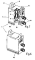
- Figures 6 and 7 show the gripping module 6 in detail. It includes a housing body 54 having a Parallel gripper 56 with two towards each other or Moving away from each other movable base jaws 58, 60, at which gripper fingers are mounted. Again, in one Cylinder space 62 opening pressure medium connections 64 are provided. A in the cylinder chamber 62 movable piston 66 is above a Piston rod 68 with a wedge-shaped Mitauerschrägen having associated control means 70, which with the Base jaws 58, 60 cooperates in such a way that after Moving the control means 70 away from each other and after moving the control means 70 toward each other are.
- the lifting module 2 and the swivel module 4 are, as shown in FIG. 1 can be seen, about that in Figure 8 in detail Coupling element 12 releasably connected together. That as Injection molded part made of plastic coupling element 12 is substantially plate or cuboid and includes in Assembly direction 72 extended engagement elements 74 in shape of latching hook 76. The latching hooks 76 extend over the entire width of the coupling element 12. The latching hooks 76 have a the respective module 2, 4 facing run-on slope 78 and are when mating coupling element 12th and module 2, 4 transversely to the mounting direction 72 deflected, which indicated by the double arrow 80.
- Lifting module 2 with its connection plate 22 against the Coupling element 12 are pressed, they run each other opposite longitudinal edges 82 (Figure 2) of the connection plate 22 against the ramps 78 and direct the latch hook 76th in the direction of arrow 80 to the outside.
- the connection plate 22 of the lifting module 2 is cantilevered out, one Level-forming edge portion 84 ( Figure 2) formed by the latching hook 76 is engaged behind. Snap the latching hooks 76 or snap behind this stage, so that Coupling element 12 is mounted on the connection plate 22.
- the coupling element 12 has at between the Rear grip elements 74 and latching hook 76 located side 86th pin-shaped projections 88 which when mated or snapping the coupling element 12 on the connection plate 22 in provided in appropriate place recesses 90th ( Figure 2) intervene.
- About these projections 88 and recesses 90 are pivotal or torsional forces between the Transfer terminal 22 and the coupling element 22 without that the latching hooks 76 are thereby burdened.
- the swivel module 4 via the in Figure 9 shown in two views coupling element 14 with connected to the gripping module 6.
- coupling element 14 are again snap hook 98 over the entire breice of the Coupling element 14 is provided.
- the the swivel module. 4 facing latch hook 98 are perpendicular to the Gripping module 6 facing latch hook 98.
- the connection plate 50th of the swivel module 4, as well as the connection plate 22 of the Hubmoduls 2 projecting edge portions 100, which of the Snap hook 98 in the manner described above are graspable. As can be seen in FIGS.
- the latching hooks 76, 98 deflected out of their rear grip position.
- a means for deflecting the latching hook 76th be introduced.
- a polygonal Angle plugged in and twisted so that the slot 108 V-shaped is widened.
- Figs. 8 and 9 Figs the coupling elements 12 and 14 open to the sides Through openings 110, 112 are provided, which as passages can serve for lines.
Landscapes
- Engineering & Computer Science (AREA)
- Robotics (AREA)
- Mechanical Engineering (AREA)
- Manipulator (AREA)
- Control And Other Processes For Unpacking Of Materials (AREA)
- Load-Engaging Elements For Cranes (AREA)
- Moulds For Moulding Plastics Or The Like (AREA)
Description
Das Schwenkmodul kann dann durch die Hubbewegung des Hubmoduls translatorisch bewegt werden. Das Schwenkmodul besitzt seinerseits eine bezüglich eines Gehäusekörpers schwenkbare Anschlussplatte, die mit einem Gehäusekörper eines Greifmoduls verschraubt werden kann. Eine derart aufgebaute Handhabungseinrichtung vermag also das werkstückzugewandte Greifmodul um eine Achse zu verdrehen und in Hubrichtung des Hubmoduls translatorisch zu verlagern. Es versteht sich, dass durch unterschiedliche Gestaltung und Kombination von Handhabungsmodulen eine Vielzahl von Handhabungseinrichtungen hergestellt werden können.
- Figur 1
- eine perspektivische Ansicht einer erfindungsgemäßen Handhabungseinrichtung;
- Figur 2
- eine perspektivische Ansicht eines Hubmoduls der Handhabungseinrichtung nach Figur 1;
- Figur 3
- eine teilweise aufgerissene Darstellung des Hubmoduls nach Figur 2;
- Figur 4
- eine perspektivische Ansicht eines Schwenkmoduls der Handhabungseinrichtung nach Figur 1;
- Figur 5
- eine teilweise aufgerissene Darstellung des Schwenkmoduls nach Figur 4;
- Figur 6
- eine perspektivische Ansicht eines Greifmoduls der Handhabungseinrichtung nach Figur 1;
- Figur 7
- eine teilweise aufgerissene Darstellung des Greifmoduls nach Figur 6;
- Figur 8
- eine perspektivische Ansicht eines Kopplungselements zum Verbinden des Hubmoduls nach Figur 2 mit dem Schwenkmodul nach Figur 4; und
- Figur 9
- zwei perspektivische Ansichten eines weiteren Kopplungselements zum Verbinden des Schwenkmoduls nach Figur 4 mit dem Greifmodul nach Figur 6.
Claims (11)
- Handhabungseinrichtung mit mehreren Handhabungsmodulen, wie Greif- (6), Hub- (2) oder Schwenkmodulen (4), die über eine Verbindungsvorrichtung (8, 10) miteinander lösbar verbindbar sind, wobei als Verbindungsvorrichtung (8, 10) ein antriebs- und getriebeloses Kopplungselement (12, 14) vorgesehen ist, dadurch gekennzeichnet, dass zum Verbinden zweier Handhabungsmodule (2, 4, 6) das jeweilige Kopplungselement (12, 14) an beiden Handhabungsmodulen (2, 4, 6), die es verbindet, schnappend, rastend und hintergreifend montierbar ist.
- Handhabungseinrichtung nach Anspruch 1, dadurch gekennzeichnet, dass das Kopplungselement (12, 14) plattenförmig ist.
- Handhabungseinrichtung nach einem der vorstehenden Ansprüche, dadurch gekennzeichnet, dass das Kopplungselement (12, 14) aus Kunststoff besteht und ein Spritzgußteil ist.
- Handhabungseinrichtung nach einem der vorstehenden Ansprüche, gekennzeichnet durch in Montagerichtung erstreckte Rasthaken (76, 98) an dem Kopplungselement (12, 14) oder einem Modul (2, 4, 6), die an einem hintergreifbaren Bereich (82, 100, 102) an dem jeweils anderen Teil in Hintergriffsstellung bringbar sind.
- Handhabungseinrichtung nach Anspruch 4, dadurch gekennzeichnet, dass die Rasthaken (76, 98) an dem Kopplungselement (12, 14) vorgesehen sind und sich in zwei entgegengesetzte Richtungen auf die miteinander zu verbindenden Module (2, 4; 4, 6) hin erstrecken.
- Handhabungseinrichtung nach Anspruch 4 oder 5, dadurch gekennzeichnet, dass die Rasthaken (76, 98) leistenförmig über im wesentlichen die gesamte Breite des Kopplungselements (12, 14) erstreckt sind.
- Handhabungseinrichtung nach Anspruch 4, 5 oder 6, dadurch gekennzeichnet, dass die Rasthaken geteilt sind.
- Handhabungseinrichtung nach einem der vorstehenden Ansprüche, dadurch gekennzeichnet, dass das Kopplungselement (12, 14) und das Modul Fixiermittel umfassen, die eine Verdrehsicherung zwischen dem Kopplungselement und dem Modul bilden.
- Handhabungseinrichtung nach Anspruch 8, dadurch gekennzeichnet, dass die Verdrehsicherung von wenigstens einem in Montagerichtung erstreckten Vorsprung (88, 104) und einer an entsprechender Stelle vorgesehenen Ausnehmung (90, 106), in welche der Vorsprung eingreift, gebildet ist.
- Handhabungseinrichtung nach einem der vorstehenden Ansprüche, dadurch gekennzeichnet, dass in dem Kopplungselement (12, 14) und in dem Modul zusätzlich Schraubendurchgangsöffnungen und Gewindeöffnungen vorgesehen sind.
- Handhabungseinrichtung nach einem der vorstehenden Ansprüche, dadurch gekennzeichnet, dass das Kopplungselement (12, 14) Durchgangsöffnungen für Leitungen aufweist.
Applications Claiming Priority (3)
| Application Number | Priority Date | Filing Date | Title |
|---|---|---|---|
| DE19712956 | 1997-03-27 | ||
| DE19712956A DE19712956A1 (de) | 1997-03-27 | 1997-03-27 | Handhabungseinrichtung |
| PCT/EP1997/006304 WO1998043783A1 (de) | 1997-03-27 | 1997-11-12 | Handhabungseinrichtung |
Publications (2)
| Publication Number | Publication Date |
|---|---|
| EP0973631A1 EP0973631A1 (de) | 2000-01-26 |
| EP0973631B1 true EP0973631B1 (de) | 2005-05-04 |
Family
ID=7824834
Family Applications (1)
| Application Number | Title | Priority Date | Filing Date |
|---|---|---|---|
| EP97951176A Expired - Lifetime EP0973631B1 (de) | 1997-03-27 | 1997-11-12 | Handhabungseinrichtung |
Country Status (4)
| Country | Link |
|---|---|
| EP (1) | EP0973631B1 (de) |
| AT (1) | ATE294675T1 (de) |
| DE (2) | DE19712956A1 (de) |
| WO (1) | WO1998043783A1 (de) |
Families Citing this family (2)
| Publication number | Priority date | Publication date | Assignee | Title |
|---|---|---|---|---|
| US6357741B1 (en) * | 2000-01-20 | 2002-03-19 | Heidelberger Druckmaschinen Ag | Velocity adjustable grippers on sliding carriage |
| CN101708608B (zh) * | 2009-11-30 | 2011-01-26 | 哈尔滨工业大学 | 用于太空环境的大型机械手 |
Family Cites Families (8)
| Publication number | Priority date | Publication date | Assignee | Title |
|---|---|---|---|---|
| US4793053A (en) * | 1987-04-16 | 1988-12-27 | General Motors Corporation | Quick disconnect device |
| DE8816782U1 (de) * | 1987-05-11 | 1990-06-21 | Gühring oHG, 72458 Albstadt | Kupplungsvorrichtung zwischen einem Werkstück- oder Werkzeugträgerteil und einer dafür vorgesehenen Handhabungseinrichtung |
| DE3918587A1 (de) * | 1988-06-13 | 1989-12-14 | Westinghouse Electric Corp | Umkonfigurierbarer gelenkiger roboterarm |
| DE4004738A1 (de) * | 1990-01-25 | 1991-08-08 | Maag Zahnraeder & Maschinen Ag | Greiferbaugruppe |
| DE4030119A1 (de) * | 1990-09-24 | 1992-03-26 | Uwe Kochanneck | Multiblock-robot |
| DE4230942A1 (de) * | 1992-09-16 | 1994-03-17 | Bach & Co | Handhabungsmodul |
| US5293107A (en) * | 1993-02-24 | 1994-03-08 | Fanuc Robotics North America, Inc. | Motorized rotary joint and method of constructing a modular robot utilizing same |
| DE4431842C2 (de) * | 1994-09-07 | 1998-10-01 | Gmd Gmbh | Elektronisch steuerbare Vorrichtung |
-
1997
- 1997-03-27 DE DE19712956A patent/DE19712956A1/de not_active Withdrawn
- 1997-11-12 DE DE59712298T patent/DE59712298D1/de not_active Expired - Lifetime
- 1997-11-12 EP EP97951176A patent/EP0973631B1/de not_active Expired - Lifetime
- 1997-11-12 WO PCT/EP1997/006304 patent/WO1998043783A1/de not_active Ceased
- 1997-11-12 AT AT97951176T patent/ATE294675T1/de not_active IP Right Cessation
Also Published As
| Publication number | Publication date |
|---|---|
| WO1998043783A1 (de) | 1998-10-08 |
| DE59712298D1 (de) | 2005-06-09 |
| DE19712956A1 (de) | 1998-10-01 |
| ATE294675T1 (de) | 2005-05-15 |
| EP0973631A1 (de) | 2000-01-26 |
Similar Documents
| Publication | Publication Date | Title |
|---|---|---|
| DE69408407T2 (de) | Leichter Handgriff | |
| DE69124736T2 (de) | Ventilverteiler | |
| EP2279317B1 (de) | Fahrzeugtürschloss mit innenauslösehebel | |
| EP2740521B1 (de) | Ventil insbesondere für ein Spielzeugbaukastensystem | |
| EP0442033A1 (de) | Ventilbaugruppe | |
| DE102008058426A1 (de) | Zubehörmontageaufbau | |
| EP0217086A2 (de) | Energieführungskette | |
| DE3544130C2 (de) | Greifer für Handhabungsgeräte | |
| DE202008005129U1 (de) | Fahrzeugtürschloss mit Befestigungsblech | |
| EP3874569A1 (de) | Kabeldurchführung | |
| AT515647A2 (de) | Leuchte | |
| EP0582258B1 (de) | Befestigungsvorrichtung | |
| EP2019216B1 (de) | Übertragungssystem | |
| EP0217151A2 (de) | Klemm-Spannvorrichtung für Seile, Bänder, Gurte o.dgl. | |
| EP0120996B1 (de) | Fördervorrichtung | |
| EP0973631A1 (de) | Handhabungseinrichtung | |
| DE20016618U1 (de) | Anhängerkupplung für Kraftfahrzeuge | |
| DE10340207A1 (de) | Elektrisches Gerät mit Halte-/Lösevorrichtung | |
| EP1978262B1 (de) | Antriebsvorrichtung | |
| DE3112049C2 (de) | Federpuffer | |
| DE4413001A1 (de) | Elektrische Verbindungsvorrichtung | |
| DE2949281C2 (de) | Betätigungsvorrichtung für einen Türverschluß, insbesondere Innenbetätigungsvorrichtung für einen Kraftfahrzeug-Türverschluß | |
| DE3528741A1 (de) | Betaetigungsvorrichtung fuer einen schalter, insbesondere an einer handwerkzeugmaschine | |
| DE3305602C2 (de) | Montageelement für Kabelführungskanäle | |
| DE102021214269B4 (de) | Türantrieb mit einem Gehäuse |
Legal Events
| Date | Code | Title | Description |
|---|---|---|---|
| PUAI | Public reference made under article 153(3) epc to a published international application that has entered the european phase |
Free format text: ORIGINAL CODE: 0009012 |
|
| AK | Designated contracting states |
Kind code of ref document: A1 Designated state(s): AT BE CH DE DK ES FI FR GB GR IE IT LI LU MC NL PT SE |
|
| 17P | Request for examination filed |
Effective date: 19990728 |
|
| RBV | Designated contracting states (corrected) |
Designated state(s): AT BE CH DE DK ES FI FR GB GR IE IT LI LU MC NL PT SE |
|
| RBV | Designated contracting states (corrected) |
Designated state(s): AT DE FR GB IT SE |
|
| GRAP | Despatch of communication of intention to grant a patent |
Free format text: ORIGINAL CODE: EPIDOSNIGR1 |
|
| GRAS | Grant fee paid |
Free format text: ORIGINAL CODE: EPIDOSNIGR3 |
|
| GRAA | (expected) grant |
Free format text: ORIGINAL CODE: 0009210 |
|
| AK | Designated contracting states |
Kind code of ref document: B1 Designated state(s): AT DE FR GB IT SE |
|
| PG25 | Lapsed in a contracting state [announced via postgrant information from national office to epo] |
Ref country code: IT Free format text: LAPSE BECAUSE OF FAILURE TO SUBMIT A TRANSLATION OF THE DESCRIPTION OR TO PAY THE FEE WITHIN THE PRESCRIBED TIME-LIMIT;WARNING: LAPSES OF ITALIAN PATENTS WITH EFFECTIVE DATE BEFORE 2007 MAY HAVE OCCURRED AT ANY TIME BEFORE 2007. THE CORRECT EFFECTIVE DATE MAY BE DIFFERENT FROM THE ONE RECORDED. Effective date: 20050504 Ref country code: GB Free format text: LAPSE BECAUSE OF FAILURE TO SUBMIT A TRANSLATION OF THE DESCRIPTION OR TO PAY THE FEE WITHIN THE PRESCRIBED TIME-LIMIT Effective date: 20050504 |
|
| REG | Reference to a national code |
Ref country code: GB Ref legal event code: FG4D Free format text: NOT ENGLISH |
|
| REG | Reference to a national code |
Ref country code: IE Ref legal event code: FG4D Free format text: LANGUAGE OF EP DOCUMENT: GERMAN |
|
| REF | Corresponds to: |
Ref document number: 59712298 Country of ref document: DE Date of ref document: 20050609 Kind code of ref document: P |
|
| PG25 | Lapsed in a contracting state [announced via postgrant information from national office to epo] |
Ref country code: SE Free format text: LAPSE BECAUSE OF FAILURE TO SUBMIT A TRANSLATION OF THE DESCRIPTION OR TO PAY THE FEE WITHIN THE PRESCRIBED TIME-LIMIT Effective date: 20050804 |
|
| PG25 | Lapsed in a contracting state [announced via postgrant information from national office to epo] |
Ref country code: AT Free format text: LAPSE BECAUSE OF NON-PAYMENT OF DUE FEES Effective date: 20051112 |
|
| GBV | Gb: ep patent (uk) treated as always having been void in accordance with gb section 77(7)/1977 [no translation filed] |
Effective date: 20050504 |
|
| PLBE | No opposition filed within time limit |
Free format text: ORIGINAL CODE: 0009261 |
|
| STAA | Information on the status of an ep patent application or granted ep patent |
Free format text: STATUS: NO OPPOSITION FILED WITHIN TIME LIMIT |
|
| 26N | No opposition filed |
Effective date: 20060207 |
|
| EN | Fr: translation not filed | ||
| PG25 | Lapsed in a contracting state [announced via postgrant information from national office to epo] |
Ref country code: FR Free format text: LAPSE BECAUSE OF NON-PAYMENT OF DUE FEES Effective date: 20051130 |
|
| PG25 | Lapsed in a contracting state [announced via postgrant information from national office to epo] |
Ref country code: FR Free format text: LAPSE BECAUSE OF NON-PAYMENT OF DUE FEES Effective date: 20050504 |
|
| PGFP | Annual fee paid to national office [announced via postgrant information from national office to epo] |
Ref country code: DE Payment date: 20150120 Year of fee payment: 18 |
|
| REG | Reference to a national code |
Ref country code: DE Ref legal event code: R119 Ref document number: 59712298 Country of ref document: DE |
|
| PG25 | Lapsed in a contracting state [announced via postgrant information from national office to epo] |
Ref country code: DE Free format text: LAPSE BECAUSE OF NON-PAYMENT OF DUE FEES Effective date: 20160601 |