EP0972148B1 - Membranventil - Google Patents
Membranventil Download PDFInfo
- Publication number
- EP0972148B1 EP0972148B1 EP98915094A EP98915094A EP0972148B1 EP 0972148 B1 EP0972148 B1 EP 0972148B1 EP 98915094 A EP98915094 A EP 98915094A EP 98915094 A EP98915094 A EP 98915094A EP 0972148 B1 EP0972148 B1 EP 0972148B1
- Authority
- EP
- European Patent Office
- Prior art keywords
- valve
- ports
- diaphragm
- valve chamber
- thresholds
- Prior art date
- Legal status (The legal status is an assumption and is not a legal conclusion. Google has not performed a legal analysis and makes no representation as to the accuracy of the status listed.)
- Expired - Lifetime
Links
Images


Classifications
-
- F—MECHANICAL ENGINEERING; LIGHTING; HEATING; WEAPONS; BLASTING
- F16—ENGINEERING ELEMENTS AND UNITS; GENERAL MEASURES FOR PRODUCING AND MAINTAINING EFFECTIVE FUNCTIONING OF MACHINES OR INSTALLATIONS; THERMAL INSULATION IN GENERAL
- F16K—VALVES; TAPS; COCKS; ACTUATING-FLOATS; DEVICES FOR VENTING OR AERATING
- F16K7/00—Diaphragm valves or cut-off apparatus, e.g. with a member deformed, but not moved bodily, to close the passage ; Pinch valves
- F16K7/12—Diaphragm valves or cut-off apparatus, e.g. with a member deformed, but not moved bodily, to close the passage ; Pinch valves with flat, dished, or bowl-shaped diaphragm
- F16K7/14—Diaphragm valves or cut-off apparatus, e.g. with a member deformed, but not moved bodily, to close the passage ; Pinch valves with flat, dished, or bowl-shaped diaphragm arranged to be deformed against a flat seat
- F16K7/16—Diaphragm valves or cut-off apparatus, e.g. with a member deformed, but not moved bodily, to close the passage ; Pinch valves with flat, dished, or bowl-shaped diaphragm arranged to be deformed against a flat seat the diaphragm being mechanically actuated, e.g. by screw-spindle or cam
-
- F—MECHANICAL ENGINEERING; LIGHTING; HEATING; WEAPONS; BLASTING
- F16—ENGINEERING ELEMENTS AND UNITS; GENERAL MEASURES FOR PRODUCING AND MAINTAINING EFFECTIVE FUNCTIONING OF MACHINES OR INSTALLATIONS; THERMAL INSULATION IN GENERAL
- F16K—VALVES; TAPS; COCKS; ACTUATING-FLOATS; DEVICES FOR VENTING OR AERATING
- F16K11/00—Multiple-way valves, e.g. mixing valves; Pipe fittings incorporating such valves
- F16K11/10—Multiple-way valves, e.g. mixing valves; Pipe fittings incorporating such valves with two or more closure members not moving as a unit
- F16K11/20—Multiple-way valves, e.g. mixing valves; Pipe fittings incorporating such valves with two or more closure members not moving as a unit operated by separate actuating members
- F16K11/207—Multiple-way valves, e.g. mixing valves; Pipe fittings incorporating such valves with two or more closure members not moving as a unit operated by separate actuating members with two handles or actuating mechanisms at opposite sides of the housing
-
- Y—GENERAL TAGGING OF NEW TECHNOLOGICAL DEVELOPMENTS; GENERAL TAGGING OF CROSS-SECTIONAL TECHNOLOGIES SPANNING OVER SEVERAL SECTIONS OF THE IPC; TECHNICAL SUBJECTS COVERED BY FORMER USPC CROSS-REFERENCE ART COLLECTIONS [XRACs] AND DIGESTS
- Y10—TECHNICAL SUBJECTS COVERED BY FORMER USPC
- Y10T—TECHNICAL SUBJECTS COVERED BY FORMER US CLASSIFICATION
- Y10T137/00—Fluid handling
- Y10T137/8593—Systems
- Y10T137/87249—Multiple inlet with multiple outlet
Definitions
- the present invention concerns a diaphragm valve for controlling a flow of gaseous or liquid fluid and, particularly, to direct such flow from at least one port of the valve to at least one other port of the valve.
- WO 95/00782 describes such a diaphragm valve including a valve housing having a substantially circular valve chamber, into which opens a central channel and on each side thereof a first side channel and a second side channel.
- Each side channel has an external connection for fluid and is separated from the central channel by means of a respective one of two substantially parallel valve seat means extending like chords across the valve chamber.
- Each valve seat means provides a substantially linear valve seat for an elastic diaphragm.
- the diaphragm is adapted to be brought into and away from sealing contact with at least one of the valve seat means.
- Two individually operable control means are adapted both to press a respective linear portion of the diaphragm against a respective valve seat, thereby to shut passage of fluid between the central channel and a respective side channel, and to positively raise a respective portion of the diaphragm off a respective one of the valve seat, thereby to open a flow passage between the central channel and the respective side channel.
- the valve housing is provided with a second substantially circular valve chamber, into which opens a fourth channel having an external connection for fluid and which communicates with the central channel through an opening in the valve housing.
- a second elastic diaphragm is provided and is adapted to be brought into and away from sealing engagement with a third valve seat means provided in the second valve chamber.
- a third control means is arranged both to press the second diaphragm against the third valve seat means, thereby to shut passage of fluid between the fourth channel and the central channel, and to release the diaphragm from its engagement with the third valve seat means, thereby to open passage of fluid between the fourth channel and the central channel.
- the new diaphragm valve shall comply with the same extensive sanitary requirements as the prior one, it shall be simply and reliably operable and have relatively few movable parts.
- valve seats can be characterized as thresholds or weirs between adjacent channels and associated ports. Communication between two ports is established by fluid passage across one or two thresholds.
- the central channel be replaced by a central space having no direct communication with any port. Fluid passage from a port to the central space must take place across a threshold, and passage from the central space to any other port must take place across a further threshold. Thus, all flow across the valve has to pass two thresholds and the central space.
- valves according to the first and second embodiments of the present invention described with reference to Figs. 1 - 4 and Figs. 5 - 9, respectively, include a valve housing having an upper and a lower valve chamber, each having valve seat means and an elastic diaphragm as well as an operating unit capable of controlling movements of the associated diaphragm so as to bring it into and away from sealing contact with the respective valve seat means.
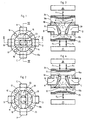
- the first embodiment of the present invention described in Figs. 1 - 5 includes a four port valve housing 10 having an upper valve chamber 11 and a lower valve chamber 12 provided in opposite parallel flat surfaces 10a, 10b of the valve housing. It appears from Figs. 1 and 2 that the valve chambers are substantially circular in plan view, and from Figs. 3 and 4 that they are substantially bowl or plate shaped in side view.
- valve seat means in the shape of weirs or thresholds 13 and 14 (Fig. 1).
- interiorly provided in the valve housing 10 are well-like channels 15, 16 (see Fig. 4) that open in the valve chamber 11 radially outside the thresholds 13, 14, respectively, and communicate with respective ports A and C.
- the lower valve chamber 12 has two parallel valve seat means in the shape of weirs or thresholds 17, 18 extending like parallel chords over the valve chamber (Fig. 2).
- Interiorly provided in the valve housing 10 are likewise well-like channels 19, 20 that open in the valve chamber 12 radially outside the thresholds 17, 18, respectively, and communicate with respective opposite ports B and D.
- the ports A and C are mutually aligned and diametrically opposed to each other as are the ports B and D. It also appears that the common axis of the channels 15 and 16 and their associated ports A and C and the common axis of the channels 19 and 20 and their associated ports B and D are perpendicular to each other, and, further, that the mutually parallel thresholds 13, 14 associated to the channels 15, 16 are perpendicular to the mutually parallel thresholds 17, 18 associated to the channels 19, 20.
- a substantially V- or funnel-shaped recess or cavity 21 (Fig. 3) tapering from substantially the diameter length of the valve chamber 11 towards the lower valve chamber 12 where it opens between the thresholds 17 and 18.
- the width of the cavity equals the distance between the thresholds 13 and 14.
- a likewise substantially V- or funnel-shaped recess or cavity 22 (shown inverted in Fig. 4) tapering from substantially the full diameter length of the valve chamber 12 towards the upper valve seat 11 where it opens between the thresholds 13 and 14.
- the width of the cavity 22 equals the distance between the thresholds 17 and 18.
- the cavities 21 and 22 form a central space 23 extending through the valve housing 10 between the valve chambers 11 and 12 and having no communication with any of the ports A, B, C and D except across a corresponding threshold 13, 14, 17 and 18, respectively.
- Figs. 3 and 4 Shown in Figs. 3 and 4 are an upper diaphragm 24 and a lower diaphragm 25 adapted for cooperation with the thresholds 13, 14 of the upper valve chamber 11 and with the thresholds 17, 18 of the lower valve chamber 12, respectively.
- the diaphragms are shown spaced from the upper surface 10a and the lower surface 10b, respectively, of the valve housing 10.
- the diaphragms are clamped between respective upper and lower operating units 26, 27 and the upper valve housing surface 10a and the lower valve housing surface 10b, respectively. Both operating units schematically shown in Figs.
- 3 and 4 are suitably of the first kind described in WO 97/17558 having two control means selectively movable in the directions indicated by arrows F 1 , F 2 , F 3 and F 4 to press one portion each of a diaphragm 24, 25 against a respective threshold 13, 14 and 17, 18, and to raise corresponding portions off the thresholds.
- F 1 , F 2 , F 3 and F 4 refer to the directions of movement of the control means of the operating units 26, 27, and a +sign implies a direction of movement to open flow passage across a threshold by raising a diaphragm portion off an associated threshold, whereas a -sign implies a direction of movement to shut flow passage across a threshold by pressing a diaphragm portion against an associated threshold.
- the second embodiment of the present invention shown in Figs. 5 - 9 includes a three-port valve housing 30 having an upper valve chamber 31 and a lower valve chamber 32 provided in opposite parallel surfaces 30a, 30b of the valve housing. It appears from Figs. 5 and 6 that the valve chambers are substantially circular in plan view and substantially bowl or plate shaped in side view.
- valve seat means in the shape of weirs or thresholds 33 and 34 (Fig. 5).
- Interiorly provided in the valve housing 30 are well-like channels 35, 36 (see Figs. 8 and 9) that open in the valve chamber 31 radially outside the thresholds 33, 34, respectively, and communicate with respective ports A' and C' that are mutually aligned and diametrically opposed to each other.
- the arrangement of the upper valve chamber 31 with its associated thresholds, channels and ports is similar to that of the upper valve chamber 11 of the first embodiment.
- the lower valve chamber 32 has but one valve seat means in the shape of a weir or threshold 37, eccentrically extending like a chord over the valve chamber (Fig. 6).
- a well-like channel 39 that opens in the valve chamber 32 radially outside the threshold 37 and communicates with a port D'.
- a recess or cavity 41 (Figs. 5 and 7) extending through the valve housing to open in the lower valve chamber 32 on the opposite side of the threshold 38 relative to the channel 39.
- the width of the cavity equals the distance between the thresholds 33 and 34 (Fig. 5).
- a recess or cavity 42 (Figs. 6 and 7) extending through the valve housing to open in the upper valve chamber 31 between the thresholds 33, 34.
- the cavities 41 and 42 form a central space 43 extending through the valve housing 10 between the valve chambers 11 and 12 and having no communication with any of the ports A', C' and D' except across a corresponding threshold 33, 34 and 38, respectively.
- Figs. 7, 8 and 9 Shown in Figs. 7, 8 and 9 are an upper diaphragm 44 and a lower diaphragm 45 adapted for cooperation with the thresholds 33, 34 of the upper valve chamber 31 and with the threshold 38 of the lower valve chamber 32, respectively.
- the diaphragms are shown spaced from the upper surface 30a and the lower surface 30b, respectively, of the valve housing 30.
- the diaphragms are clamped between respective upper and lower operating units 46, 47 and the upper valve housing surface 30a and the lower valve housing surface 30b, respectively.
- the upper operating unit 46 schematically shown in Figs.
- FIG. 7 - 9 is suitably of the first kind described in WO 97/17558 having two control means selectively movable in the directions indicated by arrows F 1 , F 2 to press one portion each of a diaphragm 44 against a respective threshold 33, 34, respectively, and to raise corresponding portions off the thresholds.
- the lower operating unit 47 schematically shown in Figs. 7 - 9 is suitably of the second kind described in WO 97/17558 having only one control means selectively movable in the directions indicated by an arrow F 5 to press a portion of a diaphragm 45 against the threshold 38 and to raise that portion off the threshold.
- F 1 , F 2 and F 5 refer to the directions of movement of the control means of the operating units 46, 47, and a +sign implies a direction of movement to open flow passage across a threshold by raising a diaphragm portion off an associated threshold, whereas a -sign implies a direction of movement to shut flow passage across a threshold by pressing a diaphragm portion against an associated threshold.
- the two valve chambers are provided in opposite parallel surfaces of the valve housing.
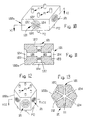
- the principles of the present invention involve a high degree of freedom as to the location of valve chambers. It would be quite possible, thus, to arrange two or more valve chambers in flat surfaces of a valve housing that are not opposite to each other provided only there is a possibility to provide "a central space", such as a channel, between them. Consequently, even two or more valve chambers provided in the very same surface would be quite possible.
- Fig. 10 is shown a perspective view of an embodiment including a valve housing block 100a having a substantially square cross section.
- One valve chamber 101 is provided in each of the four sides of the square cross section (Fig. 11).
- Each valve chamber has thresholds 102, 103 and between the thresholds a cavity 104 communicating with a corresponding cavity of each other valve chamber through internal intersecting channels 105, 106.
- Channels 107, 108 open in each valve chamber outside the thresholds 102, 103 and communicate with respective upper and lower ports P1, P2.
- Fig. 12 shows a perspective view of an embodiment having one valve chamber 101 in each of the six sides of a valve housing block 100b having the cross section of a regular hexagon.
- Internal, intersecting channels 109, 110, 111 extending between opposed valve chambers connect the cavities 104 of all valve chambers 101.
- Channels 107, 108 open in each valve chamber 101 and communicate with respective upper and lower ports P1, P2.
- Figs. 14 and 15 show a valve housing block 100c having two valve chambers 101 in an upper flat surface.
- An internal channel 112 connects the cavities 104 of the two valve chambers, and ports P1, P2 communicate with a respective valve chamber as before.
- Figs. 16 and 17 show a valve housing block 100d having two valve chambers 101 in each of two opposed flat surfaces.
- Three internal channels 113, 114, 115 interconnect all four valve chambers, and ports P1, P2, P3, P4 communicate with a respective valve chamber.
- Figs. 18 and 19 show an embodiment having a valve housing block 100e with two valve chambers 101 in each of two opposed flat surfaces and one valve chamber 101 in each of two opposed end surfaces.
- Three internal channels 116, 117, 118 interconnect all six valves, and ports P1, P2, P3, P4, P5, P6 communicate with a respective valve chamber.
Claims (5)
- Membranventil mit einem Ventilgehäuse (10; 30), das mindestens drei Anschlüsse (A, B, C, D; A', C', D') und mindestens zwei Ventilkammern (11, 12; 31, 32) in dem Ventilgehäuse aufweist, wobei jede Ventilkammer mindestens einen ersten Raum (15, 16, 19, 20; 35, 36, 39) aufweist, der mit einem zugeordneten der genannten Anschlüsse in Verbindung steht, und einen zweiten Raum (21, 22; 41, 42), der durch eine Schwelle (13, 14, 17, 18; 33, 34; 38) von dem ersten Raum getrennt ist,
dadurch gekennzeichnet, daß die zweiten Räume (21, 22; 41, 42) der Ventilkammern durch einen zentralen Raum (23; 43) hindurch miteinander kommunizieren, der keine direkte Kommunikation mit einem der genannten Anschlüsse hat, derart, daß ein Fluß zwischen irgendwelchen der genannten Anschlüsse und dem zentralen Raum nur über eine der genannten Schwellen hinweg erfolgen kann und derart, daß ein Fluß zwischen ausgewählten Kombinationen von zwei der mindestens drei Anschlüsse nur über ein Passieren von zwei Schwellen stattfinden kann. - Membranventil nach Anspruch 1, dadurch gekennzeichnet, daß der zweite Raum jeder Ventilkammer mit einem zentralen Raum des Ventilgehäuses kommuniziert, der allen der genannten zweiten Räume gemeinsam ist.
- Membranventil nach Anspruch 1 oder 2, dadurch gekennzeichnet, daß in jeder von zwei gegenüberliegenden Flächen eines Ventilgehäuseblocks (100) eine Ventilkammer angeordnet ist.
- Membranventil nach Anspruch 2 oder 3, dadurch gekennzeichnet, daß in jeder einer Vielzahl von Oberflächen eines Ventilgehäuseblocks (100a; 100b) eine Ventilkammer angeordnet ist.
- Membranventil nach Anspruch 2 oder 3, dadurch gekennzeichnet, daß in mindestens einer von einer Vielzahl von Flächen eines Ventilgehäuseblocks (100c; 100d; 100e) mehr als eine Ventilkammer angeordnet ist.
Applications Claiming Priority (3)
| Application Number | Priority Date | Filing Date | Title |
|---|---|---|---|
| SE9701242A SE510074C2 (sv) | 1997-04-04 | 1997-04-04 | Membranventil av flervägstyp |
| SE9701242 | 1997-04-04 | ||
| PCT/SE1998/000621 WO1998045629A1 (en) | 1997-04-04 | 1998-04-03 | Diaphragm valve |
Publications (2)
| Publication Number | Publication Date |
|---|---|
| EP0972148A1 EP0972148A1 (de) | 2000-01-19 |
| EP0972148B1 true EP0972148B1 (de) | 2004-03-10 |
Family
ID=20406441
Family Applications (1)
| Application Number | Title | Priority Date | Filing Date |
|---|---|---|---|
| EP98915094A Expired - Lifetime EP0972148B1 (de) | 1997-04-04 | 1998-04-03 | Membranventil |
Country Status (9)
| Country | Link |
|---|---|
| US (1) | US6250332B1 (de) |
| EP (1) | EP0972148B1 (de) |
| JP (1) | JP4776046B2 (de) |
| AT (1) | ATE261562T1 (de) |
| AU (1) | AU6935598A (de) |
| CA (1) | CA2284637C (de) |
| DE (1) | DE69822293T2 (de) |
| SE (1) | SE510074C2 (de) |
| WO (1) | WO1998045629A1 (de) |
Cited By (3)
| Publication number | Priority date | Publication date | Assignee | Title |
|---|---|---|---|---|
| DE202010003665U1 (de) | 2010-03-16 | 2010-07-15 | Bürkert Werke GmbH | Ventilknoten |
| DE202010003667U1 (de) | 2010-03-16 | 2010-07-15 | Bürkert Werke GmbH | Ventilbaugruppe |
| DE202010003666U1 (de) | 2010-03-16 | 2010-07-15 | Bürkert Werke GmbH | Ventilknoten |
Families Citing this family (14)
| Publication number | Priority date | Publication date | Assignee | Title |
|---|---|---|---|---|
| SE513253C2 (sv) | 1997-09-09 | 2000-08-07 | Robovalve Ab | Membranventil samt ventilhus för en membranventil |
| DE19913689A1 (de) | 1999-03-25 | 2000-09-28 | Focke & Co | Vorrichtung zur Steuerung strömender Medien |
| US6397887B1 (en) * | 2001-03-12 | 2002-06-04 | Itt Industries Pure-Flo Solutions Group | Valve housing with integral downstream purge |
| US6401756B1 (en) * | 2001-03-16 | 2002-06-11 | Itt Industries Pure-Flo Solutions Group | Integral sterile access/ GMP diaphragm valve |
| US6672566B2 (en) | 2001-11-13 | 2004-01-06 | Itt Manufacturing Enterprises, Inc. | Multi-use sterile access/GMP diaphragm valve housing |
| DE60317642T2 (de) * | 2003-06-11 | 2008-10-30 | Asm International N.V. | Gaszufuhrvorrichtung, Ventilanordnung und Verfahren zur Erzeugung von Reaktantpulsen mit einer Ventilanordnung |
| US7114522B2 (en) * | 2004-09-18 | 2006-10-03 | David James Silva | Adapter manifold with dual valve block |
| US7216528B2 (en) * | 2005-02-22 | 2007-05-15 | Mecanique Analytique Inc. | Diaphragm-sealed valve, analytical chromatographic system and method using the same |
| JP2007085374A (ja) * | 2005-09-20 | 2007-04-05 | Nippon Daiya Valve Co Ltd | 四方ダイヤフラム弁 |
| US20080029170A1 (en) * | 2006-08-02 | 2008-02-07 | O'reilly Edward | Three-in-one valve and control system |
| CN102537426A (zh) * | 2012-01-16 | 2012-07-04 | 南京金日轻工科技发展有限公司 | 一种四通隔膜阀 |
| GB201820691D0 (en) * | 2018-12-19 | 2019-01-30 | Ge Healthcare Bio Sciences Ab | Device for distributing a flow |
| CN111306324B (zh) * | 2020-02-26 | 2022-03-11 | 河海大学常州校区 | 一种快速切换流体通路的软体阀 |
| DE102021104849A1 (de) | 2021-03-01 | 2022-09-01 | Bürkert Werke GmbH & Co. KG | Ventilknoten |
Family Cites Families (15)
| Publication number | Priority date | Publication date | Assignee | Title |
|---|---|---|---|---|
| US3787026A (en) * | 1972-11-24 | 1974-01-22 | Honeywell Inc | Chromatography valve |
| DE3023369A1 (de) * | 1980-06-23 | 1982-01-14 | Boehringer Mannheim Gmbh, 6800 Mannheim | Aryloxypropanolamine, verfahren zu ihrer herstellung und diese verbindungen enthaltende arzneimittel |
| JP3071436B2 (ja) * | 1989-09-29 | 2000-07-31 | 沖電気工業株式会社 | サーマル印刷装置 |
| JPH03117167U (de) * | 1990-03-16 | 1991-12-04 | ||
| US5295662A (en) * | 1991-08-26 | 1994-03-22 | Masako Kiyohara | Fluid flow-controller with improved diaphragm |
| US5335691A (en) * | 1992-05-26 | 1994-08-09 | Nupro Company | High pressure diaphragm valve |
| US5277224A (en) * | 1993-03-02 | 1994-01-11 | Century Industries Inc. | Five valve manifold for use with a pressure sensing apparatus |
| US5273075A (en) * | 1993-03-25 | 1993-12-28 | Itt Corporation | Diverter valve |
| US5762314A (en) * | 1993-06-08 | 1998-06-09 | O.I. Corporation | Diaphragm valve for cryogenic applications |
| SE501377C2 (sv) | 1993-06-17 | 1995-01-30 | Ingvar Baecklund | Trevägs membranventilanordning |
| US5549134A (en) * | 1994-05-27 | 1996-08-27 | Marcvalve Corporation | Diaphragm valve |
| SE510424C2 (sv) * | 1995-11-10 | 1999-05-25 | Robovalve Ab | Membranventil |
| US5906223A (en) * | 1996-09-16 | 1999-05-25 | Itt Industries, Inc. | Chromatography valve assembly |
| FR2755522B1 (fr) * | 1996-11-05 | 1998-12-18 | Air Liquide | Dispositif de regulation de l'ecoulement de gaz ayant des masses molaires sensiblement differentes |
| US6089532A (en) * | 1998-02-12 | 2000-07-18 | Wanner Engineering, Inc. | Valve for use with agricultural sprayers |
-
1997
- 1997-04-04 SE SE9701242A patent/SE510074C2/sv unknown
-
1998
- 1998-04-03 AT AT98915094T patent/ATE261562T1/de not_active IP Right Cessation
- 1998-04-03 US US09/402,194 patent/US6250332B1/en not_active Expired - Lifetime
- 1998-04-03 WO PCT/SE1998/000621 patent/WO1998045629A1/en active IP Right Grant
- 1998-04-03 CA CA002284637A patent/CA2284637C/en not_active Expired - Fee Related
- 1998-04-03 JP JP54268798A patent/JP4776046B2/ja not_active Expired - Lifetime
- 1998-04-03 DE DE69822293T patent/DE69822293T2/de not_active Expired - Lifetime
- 1998-04-03 AU AU69355/98A patent/AU6935598A/en not_active Abandoned
- 1998-04-03 EP EP98915094A patent/EP0972148B1/de not_active Expired - Lifetime
Cited By (9)
| Publication number | Priority date | Publication date | Assignee | Title |
|---|---|---|---|---|
| DE202010003665U1 (de) | 2010-03-16 | 2010-07-15 | Bürkert Werke GmbH | Ventilknoten |
| DE202010003667U1 (de) | 2010-03-16 | 2010-07-15 | Bürkert Werke GmbH | Ventilbaugruppe |
| DE202010003666U1 (de) | 2010-03-16 | 2010-07-15 | Bürkert Werke GmbH | Ventilknoten |
| EP2366923A2 (de) | 2010-03-16 | 2011-09-21 | Bürkert Werke GmbH | Ventilbaugruppe |
| EP2366922A2 (de) | 2010-03-16 | 2011-09-21 | Bürkert Werke GmbH | Ventilknoten |
| EP2366924A2 (de) | 2010-03-16 | 2011-09-21 | Bürkert Werke GmbH | Ventilknoten |
| EP2366923A3 (de) * | 2010-03-16 | 2013-12-04 | Bürkert Werke GmbH | Ventilbaugruppe |
| EP2366924A3 (de) * | 2010-03-16 | 2013-12-04 | Bürkert Werke GmbH | Ventilknoten |
| EP2366922A3 (de) * | 2010-03-16 | 2013-12-04 | Bürkert Werke GmbH | Ventilknoten |
Also Published As
| Publication number | Publication date |
|---|---|
| SE9701242L (sv) | 1998-10-05 |
| JP4776046B2 (ja) | 2011-09-21 |
| SE510074C2 (sv) | 1999-04-19 |
| DE69822293D1 (de) | 2004-04-15 |
| ATE261562T1 (de) | 2004-03-15 |
| WO1998045629A1 (en) | 1998-10-15 |
| US6250332B1 (en) | 2001-06-26 |
| AU6935598A (en) | 1998-10-30 |
| DE69822293T2 (de) | 2005-02-17 |
| JP2001519878A (ja) | 2001-10-23 |
| CA2284637A1 (en) | 1998-10-15 |
| EP0972148A1 (de) | 2000-01-19 |
| CA2284637C (en) | 2007-01-16 |
| SE9701242D0 (sv) | 1997-04-04 |
Similar Documents
| Publication | Publication Date | Title |
|---|---|---|
| EP0972148B1 (de) | Membranventil | |
| US6688325B2 (en) | Modular fluid control system | |
| EP0859923B1 (de) | Membranventil | |
| US5178191A (en) | Modular pneumatic control systems | |
| KR100255139B1 (ko) | 전환밸브용 매니폴드 | |
| US4875500A (en) | Diaphragm type of pilot operated directional control valve | |
| JPH0949578A (ja) | 切換弁における管継手の取付け機構 | |
| KR960023956A (ko) | 전환밸브집합체 | |
| US6179006B1 (en) | Plate-type mounting base | |
| GB2173259A (en) | Hydraulic control block | |
| EP1012496B1 (de) | Membranventil und gehäuse eines membranventils | |
| GB2312477A (en) | Three-way or multi-way valve | |
| JPH1163279A (ja) | 5ポート電磁弁ボディを利用した2ポート電磁弁 | |
| US20040089837A1 (en) | Multple valve arrangement for flowing media | |
| KR930002477B1 (ko) | 유체압 밸브 시스템용 밸브 베이스 | |
| CN100497963C (zh) | 汇流型电磁阀集合体 | |
| JP2021071168A (ja) | バルブ装置および流体制御装置 | |
| WO1992004568A1 (en) | Modular pneumatic control systems | |
| JPH0434283Y2 (de) | ||
| JPS6249481B2 (de) | ||
| JPH0738831U (ja) | 弁組立体 | |
| JPS6073178A (ja) | 複合回転バルブ |
Legal Events
| Date | Code | Title | Description |
|---|---|---|---|
| PUAI | Public reference made under article 153(3) epc to a published international application that has entered the european phase |
Free format text: ORIGINAL CODE: 0009012 |
|
| 17P | Request for examination filed |
Effective date: 19990920 |
|
| AK | Designated contracting states |
Kind code of ref document: A1 Designated state(s): AT BE CH DE DK ES FI FR GB IE IT LI LU NL SE |
|
| 17Q | First examination report despatched |
Effective date: 20021009 |
|
| REG | Reference to a national code |
Ref country code: GB Ref legal event code: FG4D |
|
| GRAP | Despatch of communication of intention to grant a patent |
Free format text: ORIGINAL CODE: EPIDOSNIGR1 |
|
| GRAS | Grant fee paid |
Free format text: ORIGINAL CODE: EPIDOSNIGR3 |
|
| GRAA | (expected) grant |
Free format text: ORIGINAL CODE: 0009210 |
|
| AK | Designated contracting states |
Kind code of ref document: B1 Designated state(s): AT BE CH DE DK ES FI FR GB IE IT LI LU NL SE |
|
| PG25 | Lapsed in a contracting state [announced via postgrant information from national office to epo] |
Ref country code: NL Free format text: LAPSE BECAUSE OF FAILURE TO SUBMIT A TRANSLATION OF THE DESCRIPTION OR TO PAY THE FEE WITHIN THE PRESCRIBED TIME-LIMIT Effective date: 20040310 Ref country code: LI Free format text: LAPSE BECAUSE OF FAILURE TO SUBMIT A TRANSLATION OF THE DESCRIPTION OR TO PAY THE FEE WITHIN THE PRESCRIBED TIME-LIMIT Effective date: 20040310 Ref country code: IT Free format text: LAPSE BECAUSE OF FAILURE TO SUBMIT A TRANSLATION OF THE DESCRIPTION OR TO PAY THE FEE WITHIN THE PRESCRIBED TIME-LIMIT;WARNING: LAPSES OF ITALIAN PATENTS WITH EFFECTIVE DATE BEFORE 2007 MAY HAVE OCCURRED AT ANY TIME BEFORE 2007. THE CORRECT EFFECTIVE DATE MAY BE DIFFERENT FROM THE ONE RECORDED. Effective date: 20040310 Ref country code: FR Free format text: LAPSE BECAUSE OF FAILURE TO SUBMIT A TRANSLATION OF THE DESCRIPTION OR TO PAY THE FEE WITHIN THE PRESCRIBED TIME-LIMIT Effective date: 20040310 Ref country code: FI Free format text: LAPSE BECAUSE OF FAILURE TO SUBMIT A TRANSLATION OF THE DESCRIPTION OR TO PAY THE FEE WITHIN THE PRESCRIBED TIME-LIMIT Effective date: 20040310 Ref country code: CH Free format text: LAPSE BECAUSE OF FAILURE TO SUBMIT A TRANSLATION OF THE DESCRIPTION OR TO PAY THE FEE WITHIN THE PRESCRIBED TIME-LIMIT Effective date: 20040310 Ref country code: BE Free format text: LAPSE BECAUSE OF FAILURE TO SUBMIT A TRANSLATION OF THE DESCRIPTION OR TO PAY THE FEE WITHIN THE PRESCRIBED TIME-LIMIT Effective date: 20040310 Ref country code: AT Free format text: LAPSE BECAUSE OF FAILURE TO SUBMIT A TRANSLATION OF THE DESCRIPTION OR TO PAY THE FEE WITHIN THE PRESCRIBED TIME-LIMIT Effective date: 20040310 |
|
| REG | Reference to a national code |
Ref country code: CH Ref legal event code: EP |
|
| PG25 | Lapsed in a contracting state [announced via postgrant information from national office to epo] |
Ref country code: LU Free format text: LAPSE BECAUSE OF NON-PAYMENT OF DUE FEES Effective date: 20040403 |
|
| PG25 | Lapsed in a contracting state [announced via postgrant information from national office to epo] |
Ref country code: IE Free format text: LAPSE BECAUSE OF NON-PAYMENT OF DUE FEES Effective date: 20040405 |
|
| REG | Reference to a national code |
Ref country code: IE Ref legal event code: FG4D |
|
| REF | Corresponds to: |
Ref document number: 69822293 Country of ref document: DE Date of ref document: 20040415 Kind code of ref document: P |
|
| PG25 | Lapsed in a contracting state [announced via postgrant information from national office to epo] |
Ref country code: SE Free format text: LAPSE BECAUSE OF FAILURE TO SUBMIT A TRANSLATION OF THE DESCRIPTION OR TO PAY THE FEE WITHIN THE PRESCRIBED TIME-LIMIT Effective date: 20040610 Ref country code: GB Free format text: LAPSE BECAUSE OF NON-PAYMENT OF DUE FEES Effective date: 20040610 Ref country code: DK Free format text: LAPSE BECAUSE OF FAILURE TO SUBMIT A TRANSLATION OF THE DESCRIPTION OR TO PAY THE FEE WITHIN THE PRESCRIBED TIME-LIMIT Effective date: 20040610 |
|
| PG25 | Lapsed in a contracting state [announced via postgrant information from national office to epo] |
Ref country code: ES Free format text: LAPSE BECAUSE OF FAILURE TO SUBMIT A TRANSLATION OF THE DESCRIPTION OR TO PAY THE FEE WITHIN THE PRESCRIBED TIME-LIMIT Effective date: 20040621 |
|
| NLV1 | Nl: lapsed or annulled due to failure to fulfill the requirements of art. 29p and 29m of the patents act | ||
| REG | Reference to a national code |
Ref country code: CH Ref legal event code: PL |
|
| PLBE | No opposition filed within time limit |
Free format text: ORIGINAL CODE: 0009261 |
|
| STAA | Information on the status of an ep patent application or granted ep patent |
Free format text: STATUS: NO OPPOSITION FILED WITHIN TIME LIMIT |
|
| REG | Reference to a national code |
Ref country code: IE Ref legal event code: MM4A |
|
| GBPC | Gb: european patent ceased through non-payment of renewal fee |
Effective date: 20040610 |
|
| EN | Fr: translation not filed | ||
| 26N | No opposition filed |
Effective date: 20041213 |
|
| PGFP | Annual fee paid to national office [announced via postgrant information from national office to epo] |
Ref country code: DE Payment date: 20170426 Year of fee payment: 20 |
|
| REG | Reference to a national code |
Ref country code: DE Ref legal event code: R071 Ref document number: 69822293 Country of ref document: DE |