EP0972148B1 - Diaphragm valve - Google Patents
Diaphragm valve Download PDFInfo
- Publication number
- EP0972148B1 EP0972148B1 EP98915094A EP98915094A EP0972148B1 EP 0972148 B1 EP0972148 B1 EP 0972148B1 EP 98915094 A EP98915094 A EP 98915094A EP 98915094 A EP98915094 A EP 98915094A EP 0972148 B1 EP0972148 B1 EP 0972148B1
- Authority
- EP
- European Patent Office
- Prior art keywords
- valve
- ports
- diaphragm
- valve chamber
- thresholds
- Prior art date
- Legal status (The legal status is an assumption and is not a legal conclusion. Google has not performed a legal analysis and makes no representation as to the accuracy of the status listed.)
- Expired - Lifetime
Links
Images


Classifications
-
- F—MECHANICAL ENGINEERING; LIGHTING; HEATING; WEAPONS; BLASTING
- F16—ENGINEERING ELEMENTS AND UNITS; GENERAL MEASURES FOR PRODUCING AND MAINTAINING EFFECTIVE FUNCTIONING OF MACHINES OR INSTALLATIONS; THERMAL INSULATION IN GENERAL
- F16K—VALVES; TAPS; COCKS; ACTUATING-FLOATS; DEVICES FOR VENTING OR AERATING
- F16K7/00—Diaphragm valves or cut-off apparatus, e.g. with a member deformed, but not moved bodily, to close the passage ; Pinch valves
- F16K7/12—Diaphragm valves or cut-off apparatus, e.g. with a member deformed, but not moved bodily, to close the passage ; Pinch valves with flat, dished, or bowl-shaped diaphragm
- F16K7/14—Diaphragm valves or cut-off apparatus, e.g. with a member deformed, but not moved bodily, to close the passage ; Pinch valves with flat, dished, or bowl-shaped diaphragm arranged to be deformed against a flat seat
- F16K7/16—Diaphragm valves or cut-off apparatus, e.g. with a member deformed, but not moved bodily, to close the passage ; Pinch valves with flat, dished, or bowl-shaped diaphragm arranged to be deformed against a flat seat the diaphragm being mechanically actuated, e.g. by screw-spindle or cam
-
- F—MECHANICAL ENGINEERING; LIGHTING; HEATING; WEAPONS; BLASTING
- F16—ENGINEERING ELEMENTS AND UNITS; GENERAL MEASURES FOR PRODUCING AND MAINTAINING EFFECTIVE FUNCTIONING OF MACHINES OR INSTALLATIONS; THERMAL INSULATION IN GENERAL
- F16K—VALVES; TAPS; COCKS; ACTUATING-FLOATS; DEVICES FOR VENTING OR AERATING
- F16K11/00—Multiple-way valves, e.g. mixing valves; Pipe fittings incorporating such valves
- F16K11/10—Multiple-way valves, e.g. mixing valves; Pipe fittings incorporating such valves with two or more closure members not moving as a unit
- F16K11/20—Multiple-way valves, e.g. mixing valves; Pipe fittings incorporating such valves with two or more closure members not moving as a unit operated by separate actuating members
- F16K11/207—Multiple-way valves, e.g. mixing valves; Pipe fittings incorporating such valves with two or more closure members not moving as a unit operated by separate actuating members with two handles or actuating mechanisms at opposite sides of the housing
-
- Y—GENERAL TAGGING OF NEW TECHNOLOGICAL DEVELOPMENTS; GENERAL TAGGING OF CROSS-SECTIONAL TECHNOLOGIES SPANNING OVER SEVERAL SECTIONS OF THE IPC; TECHNICAL SUBJECTS COVERED BY FORMER USPC CROSS-REFERENCE ART COLLECTIONS [XRACs] AND DIGESTS
- Y10—TECHNICAL SUBJECTS COVERED BY FORMER USPC
- Y10T—TECHNICAL SUBJECTS COVERED BY FORMER US CLASSIFICATION
- Y10T137/00—Fluid handling
- Y10T137/8593—Systems
- Y10T137/87249—Multiple inlet with multiple outlet
Abstract
Description
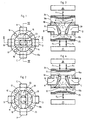
- Fig. 1 is a top view of a valve housing of a first embodiment;
- Fig. 2 is a bottom view of the valve housing according to Fig. 1;
- Fig. 3 is a vertical central section taken along line III-III in Fig. 1, but at a larger scale;
- Fig. 4 is a vertical central section taken along line IV-IV in Fig. 1, at the same scale as Fig. 3;
- Fig. 5 is a top view of a valve housing of a second embodiment;
- Fig. 6 is a bottom view of the valve housing according to Fig. 5;
- Fig. 7 is a vertical central section taken along line VII-VII in Fig. 5;
- Fig. 8 is a vertical central section taken along line VIII-VIII in Fig. 5;
- Fig. 9 is a vertical central section taken along line IX-IX in Fig. 5;
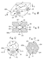
- Fig. 10 is a perspective view of a possible: third embodiment of the present invention having one valve chamber in each of the four sides of a valve housing having a square cross section;
- Fig. 11 is a section along line XI-XI of Fig. 10;
- Fig. 12 is a perspective view of a possible forth embodiment of the present invention having one valve chamber in each of the six sides of a valve housing having the cross section of a regular hexagon;
- Fig. 13 is a section along line XIII-XIII of Fig. 12;
- Fig. 14 is a perspective view of a possible fifth embodiment of the present invention including a valve housing having two valve chambers in one flat surface;
- Fig. 15 is a section along line XV-XV of Fig. 14;
- Fig. 16 is a perspective view of a possible sixth embodiment of the present invention including a valve housing having two valve chambers in each of two opposed flat surfaces;
- Fig. 17 is a section along line XVII-XVII of Fig.. 16;
- Fig. 18 is a perspective view of a seventh embodiment of the present invention including a valve housing having two valve chambers in each of two opposed flat surfaces (as in Figs. 16 and 17) and one valve chamber in each of two opposed end surfaces; and
- Fig. 19 is a section along line XIX-XIX of Fig. 18.
Interiorly provided in the
| Two-way communication between ports | ||||
| A ↔ B | C ↔ B | A + C ↔ B | A ↔ C | D ↔ B |
| F1 + | F1 - | F1 + | F1 + | F1 - |
| F2 - | F2 + | F2 + | F2 + | F2 - |
| F3 + | F3 + | F3 + | F3 - | F3 + |
| F4 - | F4 - | F4 - | F4 - | F4 + |
| Two-way communication between ports | |||
| A' ↔ D' | C' ↔ D' | A' + C' ↔ D' | A' ↔ C' |
| F1 + | F1 - | F1 + | F1 + |
| F2 - | F2 + | F2 + | F2 + |
| F5 + | F5 + | F5 + | F3 - |
Claims (5)
- A diaphragm valve including a valve housing (10; 30) having at least three ports (A, B, C, D; A', C', D') and at least two valve chambers (11, 12; 31, 32) provided in the valve housing, each valve chamber having at least one first space (15, 16, 19, 20; 35, 36, 39) communicating with a respective one of said ports and a second space (21, 22; 41, 42) separated from said first space by a threshold (13, 14, 17, 18; 33, 34; 38), characterized in that the second spaces (21, 22; 41, 42) of the valve chambers inter-communicate through a central space (23; 43) having no direct communication with any one of said ports, such that flow between any of said ports and said central space can take place only across one of said thresholds, and such that flow between any selected combination of two of said at least three ports can take place only by passing across two thresholds.
- A diaphragm valve according to claim 1, characterized in that said second space of each valve chamber communicates with a central space of the valve housing common to all of said second spaces.
- A diaphragm valve according to claim 1 or 2, characterized in that one valve chamber is arranged in each of two opposed surfaces of a valve housing block (100).
- A diaphragm valve according to claim 2 or 3, characterized in that one valve chamber is arranged in each of a plurality of surfaces of a valve housing block (100a; 100b).
- A diaphragm valve according to claim 2 or 3, characterized in that more than one valve chamber is arranged in at least one of a plurality of surfaces of a valve housing block (100c; 100d; 100e).
Applications Claiming Priority (3)
| Application Number | Priority Date | Filing Date | Title |
|---|---|---|---|
| SE9701242 | 1997-04-04 | ||
| SE9701242A SE510074C2 (en) | 1997-04-04 | 1997-04-04 | Multipath type diaphragm valve |
| PCT/SE1998/000621 WO1998045629A1 (en) | 1997-04-04 | 1998-04-03 | Diaphragm valve |
Publications (2)
| Publication Number | Publication Date |
|---|---|
| EP0972148A1 EP0972148A1 (en) | 2000-01-19 |
| EP0972148B1 true EP0972148B1 (en) | 2004-03-10 |
Family
ID=20406441
Family Applications (1)
| Application Number | Title | Priority Date | Filing Date |
|---|---|---|---|
| EP98915094A Expired - Lifetime EP0972148B1 (en) | 1997-04-04 | 1998-04-03 | Diaphragm valve |
Country Status (9)
| Country | Link |
|---|---|
| US (1) | US6250332B1 (en) |
| EP (1) | EP0972148B1 (en) |
| JP (1) | JP4776046B2 (en) |
| AT (1) | ATE261562T1 (en) |
| AU (1) | AU6935598A (en) |
| CA (1) | CA2284637C (en) |
| DE (1) | DE69822293T2 (en) |
| SE (1) | SE510074C2 (en) |
| WO (1) | WO1998045629A1 (en) |
Cited By (3)
| Publication number | Priority date | Publication date | Assignee | Title |
|---|---|---|---|---|
| DE202010003665U1 (en) | 2010-03-16 | 2010-07-15 | Bürkert Werke GmbH | valve manifold |
| DE202010003667U1 (en) | 2010-03-16 | 2010-07-15 | Bürkert Werke GmbH | valve assembly |
| DE202010003666U1 (en) | 2010-03-16 | 2010-07-15 | Bürkert Werke GmbH | valve manifold |
Families Citing this family (14)
| Publication number | Priority date | Publication date | Assignee | Title |
|---|---|---|---|---|
| SE513253C2 (en) | 1997-09-09 | 2000-08-07 | Robovalve Ab | Diaphragm valve and valve housing for a diaphragm valve |
| DE19913689A1 (en) | 1999-03-25 | 2000-09-28 | Focke & Co | Device for controlling flowing media |
| US6397887B1 (en) * | 2001-03-12 | 2002-06-04 | Itt Industries Pure-Flo Solutions Group | Valve housing with integral downstream purge |
| US6401756B1 (en) * | 2001-03-16 | 2002-06-11 | Itt Industries Pure-Flo Solutions Group | Integral sterile access/ GMP diaphragm valve |
| US6672566B2 (en) | 2001-11-13 | 2004-01-06 | Itt Manufacturing Enterprises, Inc. | Multi-use sterile access/GMP diaphragm valve housing |
| DE60317642T2 (en) * | 2003-06-11 | 2008-10-30 | Asm International N.V. | Gas supply device, valve assembly and method of generating reactant pulses with a valve assembly |
| US7114522B2 (en) * | 2004-09-18 | 2006-10-03 | David James Silva | Adapter manifold with dual valve block |
| US7216528B2 (en) * | 2005-02-22 | 2007-05-15 | Mecanique Analytique Inc. | Diaphragm-sealed valve, analytical chromatographic system and method using the same |
| JP2007085374A (en) * | 2005-09-20 | 2007-04-05 | Nippon Daiya Valve Co Ltd | Four way diaphragm valve |
| US20080029170A1 (en) * | 2006-08-02 | 2008-02-07 | O'reilly Edward | Three-in-one valve and control system |
| CN102537426A (en) * | 2012-01-16 | 2012-07-04 | 南京金日轻工科技发展有限公司 | Four-way diaphragm valve |
| GB201820691D0 (en) * | 2018-12-19 | 2019-01-30 | Ge Healthcare Bio Sciences Ab | Device for distributing a flow |
| CN111306324B (en) * | 2020-02-26 | 2022-03-11 | 河海大学常州校区 | Soft valve for quickly switching fluid passage |
| DE102021104849A1 (en) | 2021-03-01 | 2022-09-01 | Bürkert Werke GmbH & Co. KG | valve node |
Family Cites Families (15)
| Publication number | Priority date | Publication date | Assignee | Title |
|---|---|---|---|---|
| US3787026A (en) * | 1972-11-24 | 1974-01-22 | Honeywell Inc | Chromatography valve |
| DE3023369A1 (en) * | 1980-06-23 | 1982-01-14 | Boehringer Mannheim Gmbh, 6800 Mannheim | ARYLOXYPROPANOLAMINE, METHOD FOR THE PRODUCTION THEREOF AND MEDICINAL PRODUCTS CONTAINING THESE COMPOUNDS |
| JP3071436B2 (en) * | 1989-09-29 | 2000-07-31 | 沖電気工業株式会社 | Thermal printing equipment |
| JPH03117167U (en) * | 1990-03-16 | 1991-12-04 | ||
| US5295662A (en) * | 1991-08-26 | 1994-03-22 | Masako Kiyohara | Fluid flow-controller with improved diaphragm |
| US5335691A (en) * | 1992-05-26 | 1994-08-09 | Nupro Company | High pressure diaphragm valve |
| US5277224A (en) * | 1993-03-02 | 1994-01-11 | Century Industries Inc. | Five valve manifold for use with a pressure sensing apparatus |
| US5273075A (en) | 1993-03-25 | 1993-12-28 | Itt Corporation | Diverter valve |
| US5762314A (en) * | 1993-06-08 | 1998-06-09 | O.I. Corporation | Diaphragm valve for cryogenic applications |
| SE501377C2 (en) | 1993-06-17 | 1995-01-30 | Ingvar Baecklund | Three-way diaphragm valve assembly |
| US5549134A (en) * | 1994-05-27 | 1996-08-27 | Marcvalve Corporation | Diaphragm valve |
| SE510424C2 (en) | 1995-11-10 | 1999-05-25 | Robovalve Ab | diaphragm valve |
| US5906223A (en) * | 1996-09-16 | 1999-05-25 | Itt Industries, Inc. | Chromatography valve assembly |
| FR2755522B1 (en) * | 1996-11-05 | 1998-12-18 | Air Liquide | DEVICE FOR REGULATING THE GAS FLOW HAVING SUBSTANTIALLY DIFFERENT MOLAR MASSES |
| US6089532A (en) * | 1998-02-12 | 2000-07-18 | Wanner Engineering, Inc. | Valve for use with agricultural sprayers |
-
1997
- 1997-04-04 SE SE9701242A patent/SE510074C2/en unknown
-
1998
- 1998-04-03 AU AU69355/98A patent/AU6935598A/en not_active Abandoned
- 1998-04-03 CA CA002284637A patent/CA2284637C/en not_active Expired - Fee Related
- 1998-04-03 JP JP54268798A patent/JP4776046B2/en not_active Expired - Lifetime
- 1998-04-03 AT AT98915094T patent/ATE261562T1/en not_active IP Right Cessation
- 1998-04-03 DE DE69822293T patent/DE69822293T2/en not_active Expired - Lifetime
- 1998-04-03 US US09/402,194 patent/US6250332B1/en not_active Expired - Lifetime
- 1998-04-03 WO PCT/SE1998/000621 patent/WO1998045629A1/en active IP Right Grant
- 1998-04-03 EP EP98915094A patent/EP0972148B1/en not_active Expired - Lifetime
Cited By (9)
| Publication number | Priority date | Publication date | Assignee | Title |
|---|---|---|---|---|
| DE202010003665U1 (en) | 2010-03-16 | 2010-07-15 | Bürkert Werke GmbH | valve manifold |
| DE202010003667U1 (en) | 2010-03-16 | 2010-07-15 | Bürkert Werke GmbH | valve assembly |
| DE202010003666U1 (en) | 2010-03-16 | 2010-07-15 | Bürkert Werke GmbH | valve manifold |
| EP2366923A2 (en) | 2010-03-16 | 2011-09-21 | Bürkert Werke GmbH | Valve assembly |
| EP2366924A2 (en) | 2010-03-16 | 2011-09-21 | Bürkert Werke GmbH | Valve manifold |
| EP2366922A2 (en) | 2010-03-16 | 2011-09-21 | Bürkert Werke GmbH | Valve manifold |
| EP2366923A3 (en) * | 2010-03-16 | 2013-12-04 | Bürkert Werke GmbH | Valve assembly |
| EP2366922A3 (en) * | 2010-03-16 | 2013-12-04 | Bürkert Werke GmbH | Valve manifold |
| EP2366924A3 (en) * | 2010-03-16 | 2013-12-04 | Bürkert Werke GmbH | Valve manifold |
Also Published As
| Publication number | Publication date |
|---|---|
| CA2284637C (en) | 2007-01-16 |
| ATE261562T1 (en) | 2004-03-15 |
| SE510074C2 (en) | 1999-04-19 |
| JP2001519878A (en) | 2001-10-23 |
| SE9701242L (en) | 1998-10-05 |
| EP0972148A1 (en) | 2000-01-19 |
| DE69822293D1 (en) | 2004-04-15 |
| CA2284637A1 (en) | 1998-10-15 |
| WO1998045629A1 (en) | 1998-10-15 |
| AU6935598A (en) | 1998-10-30 |
| US6250332B1 (en) | 2001-06-26 |
| JP4776046B2 (en) | 2011-09-21 |
| SE9701242D0 (en) | 1997-04-04 |
| DE69822293T2 (en) | 2005-02-17 |
Similar Documents
| Publication | Publication Date | Title |
|---|---|---|
| EP0972148B1 (en) | Diaphragm valve | |
| US6688325B2 (en) | Modular fluid control system | |
| CA2235965C (en) | Diaphragm valve | |
| US5178191A (en) | Modular pneumatic control systems | |
| KR100255139B1 (en) | Transfer valve manlfold | |
| JPH06323456A (en) | Manifold valve | |
| US5749395A (en) | Selector valve aggregate | |
| US4875500A (en) | Diaphragm type of pilot operated directional control valve | |
| JPH0949578A (en) | Pipe joint installation mechanism in selector valve | |
| US6179006B1 (en) | Plate-type mounting base | |
| GB2173259A (en) | Hydraulic control block | |
| US3602246A (en) | Fluid-operated logic elements | |
| EP1012496B1 (en) | A diaphragm valve and a valve housing for a diaphragm valve | |
| GB2312477A (en) | Three-way or multi-way valve | |
| JPH1163279A (en) | Two-port solenoid valve utilizing five-port solenoid valve body | |
| KR20180129931A (en) | Major valve assembly | |
| US20040089837A1 (en) | Multple valve arrangement for flowing media | |
| KR930002477B1 (en) | Valve base with integral flow controls | |
| CN100497963C (en) | Manifold-type solenoid valve assembly | |
| JP2021071168A (en) | Valve device and fluid control device | |
| WO1992004568A1 (en) | Modular pneumatic control systems | |
| JPH0434283Y2 (en) | ||
| JP3669830B2 (en) | Compound control valve | |
| JPS6249481B2 (en) | ||
| JPH0738831U (en) | Valve assembly |
Legal Events
| Date | Code | Title | Description |
|---|---|---|---|
| PUAI | Public reference made under article 153(3) epc to a published international application that has entered the european phase |
Free format text: ORIGINAL CODE: 0009012 |
|
| 17P | Request for examination filed |
Effective date: 19990920 |
|
| AK | Designated contracting states |
Kind code of ref document: A1 Designated state(s): AT BE CH DE DK ES FI FR GB IE IT LI LU NL SE |
|
| 17Q | First examination report despatched |
Effective date: 20021009 |
|
| REG | Reference to a national code |
Ref country code: GB Ref legal event code: FG4D |
|
| GRAP | Despatch of communication of intention to grant a patent |
Free format text: ORIGINAL CODE: EPIDOSNIGR1 |
|
| GRAS | Grant fee paid |
Free format text: ORIGINAL CODE: EPIDOSNIGR3 |
|
| GRAA | (expected) grant |
Free format text: ORIGINAL CODE: 0009210 |
|
| AK | Designated contracting states |
Kind code of ref document: B1 Designated state(s): AT BE CH DE DK ES FI FR GB IE IT LI LU NL SE |
|
| PG25 | Lapsed in a contracting state [announced via postgrant information from national office to epo] |
Ref country code: NL Free format text: LAPSE BECAUSE OF FAILURE TO SUBMIT A TRANSLATION OF THE DESCRIPTION OR TO PAY THE FEE WITHIN THE PRESCRIBED TIME-LIMIT Effective date: 20040310 Ref country code: LI Free format text: LAPSE BECAUSE OF FAILURE TO SUBMIT A TRANSLATION OF THE DESCRIPTION OR TO PAY THE FEE WITHIN THE PRESCRIBED TIME-LIMIT Effective date: 20040310 Ref country code: IT Free format text: LAPSE BECAUSE OF FAILURE TO SUBMIT A TRANSLATION OF THE DESCRIPTION OR TO PAY THE FEE WITHIN THE PRESCRIBED TIME-LIMIT;WARNING: LAPSES OF ITALIAN PATENTS WITH EFFECTIVE DATE BEFORE 2007 MAY HAVE OCCURRED AT ANY TIME BEFORE 2007. THE CORRECT EFFECTIVE DATE MAY BE DIFFERENT FROM THE ONE RECORDED. Effective date: 20040310 Ref country code: FR Free format text: LAPSE BECAUSE OF FAILURE TO SUBMIT A TRANSLATION OF THE DESCRIPTION OR TO PAY THE FEE WITHIN THE PRESCRIBED TIME-LIMIT Effective date: 20040310 Ref country code: FI Free format text: LAPSE BECAUSE OF FAILURE TO SUBMIT A TRANSLATION OF THE DESCRIPTION OR TO PAY THE FEE WITHIN THE PRESCRIBED TIME-LIMIT Effective date: 20040310 Ref country code: CH Free format text: LAPSE BECAUSE OF FAILURE TO SUBMIT A TRANSLATION OF THE DESCRIPTION OR TO PAY THE FEE WITHIN THE PRESCRIBED TIME-LIMIT Effective date: 20040310 Ref country code: BE Free format text: LAPSE BECAUSE OF FAILURE TO SUBMIT A TRANSLATION OF THE DESCRIPTION OR TO PAY THE FEE WITHIN THE PRESCRIBED TIME-LIMIT Effective date: 20040310 Ref country code: AT Free format text: LAPSE BECAUSE OF FAILURE TO SUBMIT A TRANSLATION OF THE DESCRIPTION OR TO PAY THE FEE WITHIN THE PRESCRIBED TIME-LIMIT Effective date: 20040310 |
|
| REG | Reference to a national code |
Ref country code: CH Ref legal event code: EP |
|
| PG25 | Lapsed in a contracting state [announced via postgrant information from national office to epo] |
Ref country code: LU Free format text: LAPSE BECAUSE OF NON-PAYMENT OF DUE FEES Effective date: 20040403 |
|
| PG25 | Lapsed in a contracting state [announced via postgrant information from national office to epo] |
Ref country code: IE Free format text: LAPSE BECAUSE OF NON-PAYMENT OF DUE FEES Effective date: 20040405 |
|
| REG | Reference to a national code |
Ref country code: IE Ref legal event code: FG4D |
|
| REF | Corresponds to: |
Ref document number: 69822293 Country of ref document: DE Date of ref document: 20040415 Kind code of ref document: P |
|
| PG25 | Lapsed in a contracting state [announced via postgrant information from national office to epo] |
Ref country code: SE Free format text: LAPSE BECAUSE OF FAILURE TO SUBMIT A TRANSLATION OF THE DESCRIPTION OR TO PAY THE FEE WITHIN THE PRESCRIBED TIME-LIMIT Effective date: 20040610 Ref country code: GB Free format text: LAPSE BECAUSE OF NON-PAYMENT OF DUE FEES Effective date: 20040610 Ref country code: DK Free format text: LAPSE BECAUSE OF FAILURE TO SUBMIT A TRANSLATION OF THE DESCRIPTION OR TO PAY THE FEE WITHIN THE PRESCRIBED TIME-LIMIT Effective date: 20040610 |
|
| PG25 | Lapsed in a contracting state [announced via postgrant information from national office to epo] |
Ref country code: ES Free format text: LAPSE BECAUSE OF FAILURE TO SUBMIT A TRANSLATION OF THE DESCRIPTION OR TO PAY THE FEE WITHIN THE PRESCRIBED TIME-LIMIT Effective date: 20040621 |
|
| NLV1 | Nl: lapsed or annulled due to failure to fulfill the requirements of art. 29p and 29m of the patents act | ||
| REG | Reference to a national code |
Ref country code: CH Ref legal event code: PL |
|
| PLBE | No opposition filed within time limit |
Free format text: ORIGINAL CODE: 0009261 |
|
| STAA | Information on the status of an ep patent application or granted ep patent |
Free format text: STATUS: NO OPPOSITION FILED WITHIN TIME LIMIT |
|
| REG | Reference to a national code |
Ref country code: IE Ref legal event code: MM4A |
|
| GBPC | Gb: european patent ceased through non-payment of renewal fee |
Effective date: 20040610 |
|
| EN | Fr: translation not filed | ||
| 26N | No opposition filed |
Effective date: 20041213 |
|
| PGFP | Annual fee paid to national office [announced via postgrant information from national office to epo] |
Ref country code: DE Payment date: 20170426 Year of fee payment: 20 |
|
| REG | Reference to a national code |
Ref country code: DE Ref legal event code: R071 Ref document number: 69822293 Country of ref document: DE |