JP4776046B2 - Diaphragm valve - Google Patents
Diaphragm valve Download PDFInfo
- Publication number
- JP4776046B2 JP4776046B2 JP54268798A JP54268798A JP4776046B2 JP 4776046 B2 JP4776046 B2 JP 4776046B2 JP 54268798 A JP54268798 A JP 54268798A JP 54268798 A JP54268798 A JP 54268798A JP 4776046 B2 JP4776046 B2 JP 4776046B2
- Authority
- JP
- Japan
- Prior art keywords
- valve
- diaphragm
- ports
- space
- chamber
- Prior art date
- Legal status (The legal status is an assumption and is not a legal conclusion. Google has not performed a legal analysis and makes no representation as to the accuracy of the status listed.)
- Expired - Lifetime
Links
Images


Classifications
-
- F—MECHANICAL ENGINEERING; LIGHTING; HEATING; WEAPONS; BLASTING
- F16—ENGINEERING ELEMENTS AND UNITS; GENERAL MEASURES FOR PRODUCING AND MAINTAINING EFFECTIVE FUNCTIONING OF MACHINES OR INSTALLATIONS; THERMAL INSULATION IN GENERAL
- F16K—VALVES; TAPS; COCKS; ACTUATING-FLOATS; DEVICES FOR VENTING OR AERATING
- F16K7/00—Diaphragm valves or cut-off apparatus, e.g. with a member deformed, but not moved bodily, to close the passage ; Pinch valves
- F16K7/12—Diaphragm valves or cut-off apparatus, e.g. with a member deformed, but not moved bodily, to close the passage ; Pinch valves with flat, dished, or bowl-shaped diaphragm
- F16K7/14—Diaphragm valves or cut-off apparatus, e.g. with a member deformed, but not moved bodily, to close the passage ; Pinch valves with flat, dished, or bowl-shaped diaphragm arranged to be deformed against a flat seat
- F16K7/16—Diaphragm valves or cut-off apparatus, e.g. with a member deformed, but not moved bodily, to close the passage ; Pinch valves with flat, dished, or bowl-shaped diaphragm arranged to be deformed against a flat seat the diaphragm being mechanically actuated, e.g. by screw-spindle or cam
-
- F—MECHANICAL ENGINEERING; LIGHTING; HEATING; WEAPONS; BLASTING
- F16—ENGINEERING ELEMENTS AND UNITS; GENERAL MEASURES FOR PRODUCING AND MAINTAINING EFFECTIVE FUNCTIONING OF MACHINES OR INSTALLATIONS; THERMAL INSULATION IN GENERAL
- F16K—VALVES; TAPS; COCKS; ACTUATING-FLOATS; DEVICES FOR VENTING OR AERATING
- F16K11/00—Multiple-way valves, e.g. mixing valves; Pipe fittings incorporating such valves
- F16K11/10—Multiple-way valves, e.g. mixing valves; Pipe fittings incorporating such valves with two or more closure members not moving as a unit
- F16K11/20—Multiple-way valves, e.g. mixing valves; Pipe fittings incorporating such valves with two or more closure members not moving as a unit operated by separate actuating members
- F16K11/207—Multiple-way valves, e.g. mixing valves; Pipe fittings incorporating such valves with two or more closure members not moving as a unit operated by separate actuating members with two handles or actuating mechanisms at opposite sides of the housing
-
- Y—GENERAL TAGGING OF NEW TECHNOLOGICAL DEVELOPMENTS; GENERAL TAGGING OF CROSS-SECTIONAL TECHNOLOGIES SPANNING OVER SEVERAL SECTIONS OF THE IPC; TECHNICAL SUBJECTS COVERED BY FORMER USPC CROSS-REFERENCE ART COLLECTIONS [XRACs] AND DIGESTS
- Y10—TECHNICAL SUBJECTS COVERED BY FORMER USPC
- Y10T—TECHNICAL SUBJECTS COVERED BY FORMER US CLASSIFICATION
- Y10T137/00—Fluid handling
- Y10T137/8593—Systems
- Y10T137/87249—Multiple inlet with multiple outlet
Abstract
Description
本発明は、気体状または液状流体の流れを制御するダイヤフラムバルブに関し、詳述するとこのような流体をバルブの少なくとも1つのポート(流体出入口)から他の少なくとも1つのポートへと導くダイヤフラムバルブに関する。
本願発明者による国際公開第WO95/00782号に、この種のダイヤフラムバルブが開示されており、このダイヤフラムバルブは実質的に環状のバルブチャンバーを有するバルブハウジングからなり、このバルブチャンバー内に開口するこのハウジングの中央に位置するチャネルと、この中央チャネルの両側に位置する第1および第2側部チャネルとを有する。各側部チャネルは、流体を流通させるために外部と接続し、バルブを横切ってコードのように延びる2つの平行なバルブシートによってそれぞれ、中央チャネルから離隔されている。各バルブシートは、弾性のダイヤフラム用に実質的に直線状に構成されている。ダイヤフラムは、少なくとも1つのバルブシートと密閉自在に接触するように設けられている。また2つの個々に作動する手段が設けられており、これら手段は、対応するダイヤフラムの直線状部分を各バルブシートに押圧するように設けられており、これにより中央チャネルと各側部チャネル間の流体通路を遮断し、また対応するバルブシートからダイヤフラムを上昇させて、中央チャネルと各側部チャネル間の流体通路を開放するように設けられている。
この公知の3方向/3ポート(three-way/three-port)ダイヤフラムバルブは、良好に作動することが証明されている。このバルブを4方向/4ポートバルブ、即ち3つの流体の流れを混合するバルブまたは1つの外部接続部(入り口)から1つまたは3つ以上の外部接続部(出口)へと流体を導くバルブへと変換する要求が高まっている。
このことは上記ダイヤフラムバルブを改良することによって達成された。この改良されたダイヤフラムバルブは、同じ発明者による国際公開第WO95/00782号に詳述されている。この改良型ダイヤフラムバルブでは、バルブハウジングには実質的に環状の第2バルブチャンバーが設けられており、このチャンバー内には流体を流通させるために外部と接続した第4のチャンバーが開口しており且つこのチャンバーはバルブハウジングの開口部を介して中央チャネルと連通している。第2の弾性ダイヤフラムには第2のバルブチャンバーに設けられた第3のバルブシートと密閉自在に係合するように設けられている。第3の制御手段が、第2ダイヤフラムを第3のバルブシートに押圧して第4チャネルと中央チャネル間の流体通路を遮断し、またダイヤフラムと第3バルブシートとの係合を解除することにより第4チャネルと中央チャネル間の流体の通路を開放するように設けられている。
このバルブも充分目的を達成するものであった。
これら2つの公知のバルブに共通しているのは、中央に位置するチャネルがその関連するポートと直接連通しているということである。従ってこのポートは、WO95/00782号では残りの2つのポート間の流体の移動に拘わり、WO97/17558号ではバルブの残りの3つのポートの内の2つのポート間の流体の移動に拘わっている。
本発明の目的は、少なくとも2つのポートの組み合わせにおいて他のポートを介在させずに流体を移動させることができるダイヤフラムバルブを提供することである。この目的を達成するにあたって、この新しいダイヤフラムバルブは、従来品と同じように衛生面において必要な要件を満たしており且つ操作においても簡単且つ信頼性が高くまた比較的少ない数の可動部材が用いられている。
このダイヤフラムバルブでは、バルブシートは隣接するチャネルおよび関連するポートの間の堰として機能するという特徴を有する。2つのポートは、1つの堰を横切る流体経路によって連通する。
本発明の目的を達成するために中央チャネルをいずれのポートとも直接連通させない空間に変えることによって達成される。これにより流体は、ポートからこの中央の空間へ堰を越えて流れなければならず且つ中央の空間からいずれのポートへは別の堰を越えて流れなければならない。従ってバルブを横断する流体は、一度中央の空間を通過しなければならない。
本発明の具体的な態様を添付の図面を参照し、より詳しく説明する。
図1は、第1の態様のバルブハウジングの上面図である。
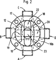
図2は、図1のバルブハウジングの底面図である。
図3は、図1のIII−III線に沿った拡大中央縦断面図である。
図4は、図3と同じ倍率に拡大した図1のIV−IV線に沿った中央縦断面図である。
図5は、第2の態様のバルブハウジングの上面図である。
図6は、図5のバルブハウジングの底面図である。
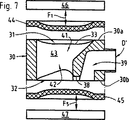
図7は、図5のVII−VII線に沿った拡大中央縦断面図である。
図8は、図5のVIII−VIII線に沿った拡大中央縦断面図である。
図9は、図5のIX−IX線に沿った拡大中央縦断面図である。
図10は、方形断面を有するバルブハウジングの4つの側部のそれぞれに1つのバルブチャンバーを有する本発明の第3の態様の斜視図である。
図11は、図10のXI−XI線に沿った断面図である。
図12は、正六角形の横断面を有するバルブハウジングの6つの側部のそれぞれに1つのバルブチャンバーを有する本発明の第4の態様の斜視図である。
図13は、図12のXIII−XIII線に沿った断面図である。
図14は、1つの平坦な面に2つのバルブチャンバーを有するバルブハウジングを含む本発明の第4の態様の斜視図である。
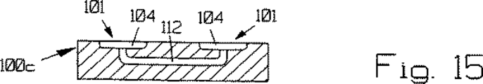
図15は、図14のXV−XV線に沿った断面図である。
図16は、2つの対向する平坦面の各々に2つのバルブチャンバーを有するバルブハウジングを含む本発明の第6の態様の斜視図である。
図17は、図16のXVII−XVII線に沿った断面図である。
図18は、2つの対向する平坦面の各々に2つのバルブチャンバー(図16、17のように)および1つのバルブチャンバーを有するバルブハウジングを含む本発明の第7の態様の斜視図である。
図19は、図18のXIX−XIX線に沿った断面図である。
WO97/17558に開示されている膜式バルブと同様に、図1〜4及び図5〜9それぞれに示す本発明の第1及び第2の態様のバルブは、上下バルブチャンバーを有するバルブハウジングからなり、各バルブチャンバーはバルブシートと弾性ダイヤフラム、さらには対応するダイヤフラムの動きを制御してダイヤフラムを各バルブシートに接触させたり離したりする作動ユニットとを有する。
本発明にはWO97/17558に詳述されている作動ユニットを用いるのが好ましいので、ここでは作動ユニットの具体的な説明は省略する。
図1〜5に示す本発明の第1の態様のバルブは、バルブハウジングの対向する平行な平坦面10a、10bに設けられた上方バルブチャンバー11及び下方バルブチャンバー12を有する4つのポートが設けられたバルブハウジング10から構成されている。図1及び図2から明らかなようにバルブチャンバーは、平面において実質的に環状であり、図3及び4から明らかなように側面において椀状またはプレート状になっている。
上部バルブチャンバー11を横断してコード状に平行に延びているのは、堰状に形成された2つのバルブシート13、14である。バルブハウジング10の内部に設けられているのは、チャネル15,16であり(図4参照)、これらチャンバーは、それぞれバルブシート13,14の外側からバルブチャンバー11内に開口しており、対応するポートA及びCに連通している。
同様に下方バルブチャンバー12もこれを横切ってコード状に延びる堰状に形成された2つの平行なバルブシート17,18を有する。バルブハウジング10の内部には、同様にバルブシート17,18の外側からバルブチャンバー12内に開口し、対向するポートB及びDにそれぞれ連通するチャネル19,20が設けられている。
図1及び2から明らかなようにポートA及びCは、互いに整合位置にありポートBとDと同様に互いに対角線上にて対向している。チャネル15,16及びその対応するポートA及びCの共通な軸とチャネル19,20及びその対応するポートB及びDの共通軸は、互いに直交しており、チャネル15,16に対応する互いに平行に延びるバルブシート13,14は、チャネル19,20に対応する互いに平行に延びるバルブシート17,18に直行している。
上方バルブチャンバー11のバルブシート13,14の間には、バルブチャンバー11の直径の幅からバルブシート17,18の間で開口する下方バルブチャンバーの方へとテーパーした実質的にV字状の凹部21(図3参照)が設けられている。凹部21の幅は、バルブシート13,14間の距離に等しい。同じように下方バルブチャンバー12のバルブシート17,18の間には、同様にV字状の凹部22(図4参照)が設けられており、この凹部22はバルブチャンバー12の幅からバルブシート13,14の間で開口する上方バルブチャンバーの方へとテーパーしている。凹部22の幅は、バルブシート17,18の間の距離に等しい。
凹部21,22が共にバルブハウジング10を縦方向に横断するようにバルブチャンバー11,12の間を延び且つ対応するバルブシート13,14,17,18を経由する以外、ポートA,B,C及びDのいずれとも連通しない中央に位置する空間23を形成する。
図3及び4に符号24,25で示すのは、上方バルブチャンバー11のバルブシート13,14と下方バルブチャンバー12のバルブシート17,18とそれぞれ協働する上方及び下方ダイヤフラムである。バルブハウジングの詳細を示すのを邪魔しないように図面では、ダイヤフラムは、バルブハウジング10の上下面10a及び下面10bのそれぞれから離して示している。実際の作動においては、ダイヤフラムは、各上方及び下方作動ユニット26,27とバルブハウジングの上下面10a及び10bの間でクランプされている。図3及び4で略式に示している2つの作動ユニットとしては、各ダイヤフラム24,25の一部をバルブシート13,14,17及び18に押圧する及びバルブシートから上昇させるために矢印F1,F2,F3及びF4にて示す方向に選択的に可動な2つの制御手段を有するWO97/17558に詳述されているものが好適である。
ここで、ダイヤフラムの1部を押圧及び上昇させることによる異なる組み合わせを選択することによって異なるポート間でどのように流体が流れるかを下記の表に示す。

図5〜9に示す本発明の第2の態様は、3つのポートを有するバルブハウジング30からなり、このハウジングはその平行な対向面30a、30bに設けられた上方バルブチャンバー31と下方バルブチャンバー32を有する。図5及び6から明らかなようにバルブチャンバーは、平面にて実質的に環状であり且つ側面にて椀状またはプレート状である。
上方バルブチャンバー31を横断して平行にコード状に延びているのは、堰状に形成された2つのバルブシート33,34である。バルブハウジング30の内部にはバルブシート33,34の外側からバルブチャンバー31に開口し、対応するポートA’及びC’に連通しているチャネル35,36が設けられており、ポートA’及びC’は、互いに整合位置にあり且つ互いに対角線上で対向している。これらの図からも明らかなように上方バルブチャンバー31とそれに対応するバルブシートとチャネル及びポートの配置は、第1の態様のものと類似している。
下方バルブチャンバー32は、堰状に形成されたバルブシート37を1つ有し、このバルブシートはバルブチャンバーをコード状に偏心して延びている。バルブハウジング30の内部には、バルブシート37の外側からバルブチャンバー32に開口し、ポートD’と連通するチャネル39が設けられてる。
図5及び6から明らかなようにチャネル35,36とこれらに対応するポートA’,C’の共通の軸とチャネル39とこれに対応するポートD’の共通の軸は、互いに直行しており、さらにチャネル35,36に平行に延びるバルブシート33,34は、チャネル39に対応するバルブシート38に直交している。
上方バルブチャンバー31のバルブシート33,34の間には、チャネル39に対してバルブシート38の対向側部上の下方バルブチャンバー32に開口するためのバルブハウジングを介して延びる凹部41(図5及び7参照)が設けられている。この凹部の幅は、バルブシート33,34間の距離に等しい(図5参照)。
また下方バルブチャンバーには、チャネル39に対してバルブシート38の対向側部にバルブシート33,34間の上方バルブチャンバーに開口するためにバルブハウジングを介して延びる凹部42が設けられている(図6及び7参照)。
凹部41,42は共にバルブチャンバー11,12の間をバルブハウジング10を介して延び且つ対応するバルブシート33,34及び38を経由する以外、ポートA’,C’及びD’のいずれとも連通しない中央に位置する空間43を形成する。
図7,8及び9に上方バルブチャンバー31のバルブシート33,34とまた下方バルブチャンバー32のバルブシート38と協働するように設けられた上方及び下方ダイヤフラム44,45が示されている。バルブハウジングの詳細を示すのを邪魔しないように図面では、ダイヤフラムは、バルブハウジング30の上下面30a及び下面30bのそれぞれから離して示している。実際の作動においては、ダイヤフラムは、各上方及び下方作動ユニット46,47とバルブハウジングの上下面30a及び30bの間でクランプされている。図3及び4と同様に図7〜9にて略式に示している上方作動ユニットとしては、各ダイヤフラム44の一部をバルブシート33,34に押圧する及びバルブシートから上昇させるために矢印F1及びF2にて示す方向に選択的に可動な2つの制御手段を有するWO97/17558に詳述されている第1の作動ユニットが好適である。図7〜9に略式に示す下方作動ユニット47としては、ダイヤフラム45の一部をバルブシート38に押圧及びバルブシートからダイヤフラムのその部分を上昇させるために矢印F5にて示す方向に選択的に可動な1つの制御手段を有するWO97/17558に詳述されている第2の作動ユニットが好適である。
ここで、ダイヤフラムの1部を押圧及び上昇させることによる異なる組み合わせを選択することによって異なるポート間でどのように流体が流れるかを下記の表に示す。
本発明の第1及び第2の態様では、2つのバルブチャンバーがバルブハウジングの対向する平行な面に設けられている。しかしながら、本発明の最も重要な特徴は、バルブチャンバーを自由に位置させることができることである。従って中央にチャネルのような空間がバルブチャンバーの間に設けられば、互いに対向しないバルブハウジングの平坦面に2つ以上のバルブチャンバーを配することも可能である。従って2つ以上のバルブチャンバーを同一平面上に設けることも可能である。
このような可能なバルブチャンバーの構成の例のいくつかを図10−19を参照し説明する。
図10は、実質的に四角形断面を有するバルブハウジング100aからなるダイヤフラムバルブの斜視図である。1つのバルブ101が、四角形断面の4つの側部に各々設けられている(図11参照)。バルブチャンバー101は、それぞれバルブシート102,103を有し、これらの間にハウジング内部で交差するチャネル105,106を介して互いに対応するバルブチャンバーの凹部と連通する凹部104を有する。チャネル107,108は、バルブシート102,103の外側にそれぞれ開口し、各上下ポートP1,P2と連通している。
図12は、正六角形の断面を有するバルブハウジングブロック100bの6つの側部の各々に1つのバルブチャンバー101を有するダイヤフラムバルブの斜視図である。バルブハウジングの内部では、対向するバルブチャンバーの間を延びて交差するチャネル109,110,111(図13参照)が、全てのバルブチャンバー101の凹部104に接続している。チャネル107,108は、各々バルブチャンバー101に開口し、各上下ポートP1,P2と連通している。
図14及び15は、上部平坦面に2つのバルブチャンバーを有するバルブハウジングブロック100cを示している。内部チャネル112は、2つのバルブチャンバーの凹部104に接続しており、ポートP1、P2が対応するバルブチャンバーに連通している。
図16及び17は、2つの対向する平坦面の各々に2つのバルブチャンバー101を有するバルブハウジングブロック100dを示す。3つの内部チャネルは、4つの全てのバルブチャンバーと相互に接続しており、ポートP1、P2、P3、P4は、対応するバルブチャンバーと接続している。
図18及び19は、2つの対向する平坦面の各々に2つのバルブチャンバー101と2つの対向する端部面の各々に1つのバルブチャンバー101とを有するバルブハウジングブロック100eを示す。3つの内部チャネル116,117,118は、6つの全てのバルブと相互に接続しており、ポートP1、P2、P3、P4、P5、P6は、各対応するバルブチャンバーに連通している。The present invention relates to a diaphragm valve for controlling the flow of a gaseous or liquid fluid, and more particularly to a diaphragm valve for guiding such fluid from at least one port (fluid inlet / outlet) of the valve to at least one other port.
International Publication No. WO 95/00782 by the inventor of the present application discloses a diaphragm valve of this kind, which comprises a valve housing having a substantially annular valve chamber, which opens into the valve chamber. It has a channel located in the center of the housing and first and second side channels located on both sides of the central channel. Each side channel is separated from the central channel by two parallel valve seats that connect to the outside for fluid flow and extend like a cord across the valve. Each valve seat is configured substantially linearly for an elastic diaphragm. The diaphragm is provided so as to be in a hermetic contact with at least one valve seat. There are also two individually actuating means, which are provided to press the corresponding diaphragm linear part against each valve seat, so that between the central channel and each side channel. The fluid passage is blocked and the diaphragm is raised from the corresponding valve seat to open the fluid passage between the central channel and each side channel.
This known three-way / three-port diaphragm valve has proven to work well. This valve is a 4-way / 4-port valve, ie a valve that mixes three fluid flows or a valve that directs fluid from one external connection (inlet) to one or more external connections (outlet) There is a growing demand for conversion.
This was achieved by improving the diaphragm valve. This improved diaphragm valve is described in detail in WO 95/00782 by the same inventor. In this improved diaphragm valve, a substantially annular second valve chamber is provided in the valve housing, and a fourth chamber connected to the outside is opened in this chamber to allow fluid to flow therethrough. The chamber communicates with the central channel through an opening in the valve housing. The second elastic diaphragm is provided so as to be hermetically engaged with a third valve seat provided in the second valve chamber. The third control means presses the second diaphragm against the third valve seat to block the fluid passage between the fourth channel and the central channel, and releases the engagement between the diaphragm and the third valve seat. A fluid passage is provided between the fourth channel and the central channel.
This valve also achieved its purpose.
Common to these two known valves is that the centrally located channel is in direct communication with its associated port. This port is therefore involved in the movement of fluid between the remaining two ports in WO 95/00782 and in the movement of fluid between two of the remaining three ports of the valve in WO 97/17558. Yes.
An object of the present invention is to provide a diaphragm valve capable of moving a fluid without interposing another port in a combination of at least two ports. In order to achieve this purpose, this new diaphragm valve satisfies the requirements for hygiene as in the case of conventional products, is simple and reliable in operation, and uses a relatively small number of movable members. ing.
In this diaphragm valve, the valve seat is characterized by functioning as a weir between adjacent channels and associated ports. The two ports are in communication by a fluid path across one weir.
In order to achieve the object of the present invention, this is accomplished by changing the central channel to a space that is not in direct communication with any port. Thus, fluid must flow from the port to this central space over the weir and from the central space to any port over another weir. Thus, the fluid traversing the valve must pass through the central space once.
Specific embodiments of the present invention will be described in more detail with reference to the accompanying drawings.
FIG. 1 is a top view of the valve housing according to the first embodiment.
2 is a bottom view of the valve housing of FIG.
FIG. 3 is an enlarged central longitudinal sectional view taken along line III-III in FIG.
4 is a central longitudinal sectional view taken along line IV-IV in FIG. 1 enlarged to the same magnification as FIG.
FIG. 5 is a top view of the valve housing of the second embodiment.
6 is a bottom view of the valve housing of FIG.
FIG. 7 is an enlarged central longitudinal sectional view taken along line VII-VII in FIG.
FIG. 8 is an enlarged central longitudinal sectional view taken along line VIII-VIII in FIG.
FIG. 9 is an enlarged central longitudinal sectional view taken along line IX-IX in FIG.
FIG. 10 is a perspective view of a third embodiment of the present invention having one valve chamber on each of the four sides of a valve housing having a square cross section.
11 is a cross-sectional view taken along line XI-XI in FIG.
FIG. 12 is a perspective view of a fourth embodiment of the present invention having one valve chamber on each of the six sides of a valve housing having a regular hexagonal cross section.
13 is a cross-sectional view taken along line XIII-XIII in FIG.
FIG. 14 is a perspective view of a fourth aspect of the present invention including a valve housing having two valve chambers on one flat surface.
15 is a cross-sectional view taken along line XV-XV in FIG.
FIG. 16 is a perspective view of a sixth aspect of the present invention including a valve housing having two valve chambers on each of two opposing flat surfaces.
17 is a cross-sectional view taken along the line XVII-XVII in FIG.
FIG. 18 is a perspective view of a seventh embodiment of the present invention including a valve housing having two valve chambers (as in FIGS. 16 and 17) and one valve chamber on each of two opposing flat surfaces.
FIG. 19 is a cross-sectional view taken along line XIX-XIX in FIG.
Similar to the membrane valve disclosed in WO 97/17558, the valves of the first and second aspects of the present invention shown in FIGS. 1 to 4 and 5 to 9 respectively comprise a valve housing having upper and lower valve chambers. Each valve chamber has a valve seat and an elastic diaphragm, as well as an operating unit that controls the movement of the corresponding diaphragm to bring the diaphragm into contact with or separate from each valve seat.
Since it is preferable to use the operating unit detailed in WO97 / 17558 in the present invention, the specific description of the operating unit is omitted here.
The valve of the first aspect of the present invention shown in FIGS. 1 to 5 is provided with four ports having an
Extending in parallel to the cord shape across the
Similarly, the
As apparent from FIGS. 1 and 2, the ports A and C are in alignment with each other and face each other diagonally in the same manner as the ports B and D. The common axis of
Between the
Ports A, B, C, except that the
Here, the following table shows how fluid flows between different ports by selecting different combinations by pressing and raising a portion of the diaphragm.
The second embodiment of the present invention shown in FIGS. 5 to 9 includes a
Two
The
As apparent from FIGS. 5 and 6, the common axes of the
Between the valve seats 33, 34 of the
The lower valve chamber is provided with a
The
FIGS. 7, 8 and 9 show the upper and
Here, the following table shows how fluid flows between different ports by selecting different combinations by pressing and raising a portion of the diaphragm.
In the first and second aspects of the present invention, two valve chambers are provided on opposite parallel surfaces of the valve housing. However, the most important feature of the present invention is that the valve chamber can be freely positioned. Therefore, if a space such as a channel is provided between the valve chambers in the center, it is possible to arrange two or more valve chambers on the flat surface of the valve housing that does not face each other. Therefore, it is possible to provide two or more valve chambers on the same plane.
Some examples of such possible valve chamber configurations are described with reference to FIGS. 10-19.
FIG. 10 is a perspective view of a diaphragm valve comprising a valve housing 100a having a substantially rectangular cross section. One
FIG. 12 is a perspective view of a diaphragm valve having one
14 and 15 show a
16 and 17 show a
18 and 19 illustrate a
Claims (5)
制御手段が設けられ、該制御手段が前記ダイヤフラム(24、25)の一部に係合し、該ダイヤフラムの一部を前記堰(13、14、17、18;33、34;38)のうち、該ダイヤフラムの一部と対応する堰に対して押圧し、また、該ダイヤフラムの一部を該堰から上昇させ、もって前記3つ以上のポート(ABCD;A’B’C’D’)の任意の2つのポート間での連通が前記堰(13、14、17、18;33、34;38)の2つを通過してのみ生じるように選択的に移動可能なことを特徴とするダイヤフラムバルブ。A da unpleasant Fulham valve, three or more ports (ABCD; A'B'C'D ') and the valve housing at least two or more valves chambers is provided; is provided (10 30), each valve A chamber (11, 12; 31, 32) is in fluid communication with at least one first space formed by the channel (15, 16, 19, 20; 35, 36, 39), the channel of the port Each valve chamber (11, 12; 31, 32) is in fluid communication with a second space formed by a recess (21, 22; 31, 32), and the second space is a weir ( 13, 14, 17, 18; 33, 34; 38) and is separated from the first space, and the diaphragm valve includes the weir (13, 14, 17, 18; 33, 34; 38) Die working with Flams (24, 25) are provided, and the second space passes through a central space (23; 43) that is not in direct communication with any of the ports (ABCD; A'B'C'D '). In fluid diaphragm valves that are in communication with each other,
Control means are provided to engage the portion of the control means of the previous SL diaphragm (24, 25), said weir portions of the diaphragm (13,14,17,18; 38; 33, 34) among presses against the weir corresponding to a portion of the diaphragm, also increase the portion of the diaphragm from the weir, with by the three or more ports (ABCD; A'B'C'D ') Communication between any two ports is selectively movable so that it only occurs through two of the weirs (13, 14, 17, 18; 33, 34; 38). Diaphragm valve.
Applications Claiming Priority (3)
| Application Number | Priority Date | Filing Date | Title |
|---|---|---|---|
| SE9701242-1 | 1997-04-04 | ||
| SE9701242A SE510074C2 (en) | 1997-04-04 | 1997-04-04 | Multipath type diaphragm valve |
| PCT/SE1998/000621 WO1998045629A1 (en) | 1997-04-04 | 1998-04-03 | Diaphragm valve |
Publications (2)
| Publication Number | Publication Date |
|---|---|
| JP2001519878A JP2001519878A (en) | 2001-10-23 |
| JP4776046B2 true JP4776046B2 (en) | 2011-09-21 |
Family
ID=20406441
Family Applications (1)
| Application Number | Title | Priority Date | Filing Date |
|---|---|---|---|
| JP54268798A Expired - Lifetime JP4776046B2 (en) | 1997-04-04 | 1998-04-03 | Diaphragm valve |
Country Status (9)
| Country | Link |
|---|---|
| US (1) | US6250332B1 (en) |
| EP (1) | EP0972148B1 (en) |
| JP (1) | JP4776046B2 (en) |
| AT (1) | ATE261562T1 (en) |
| AU (1) | AU6935598A (en) |
| CA (1) | CA2284637C (en) |
| DE (1) | DE69822293T2 (en) |
| SE (1) | SE510074C2 (en) |
| WO (1) | WO1998045629A1 (en) |
Families Citing this family (17)
| Publication number | Priority date | Publication date | Assignee | Title |
|---|---|---|---|---|
| SE513253C2 (en) | 1997-09-09 | 2000-08-07 | Robovalve Ab | Diaphragm valve and valve housing for a diaphragm valve |
| DE19913689A1 (en) | 1999-03-25 | 2000-09-28 | Focke & Co | Device for controlling flowing media |
| US6397887B1 (en) * | 2001-03-12 | 2002-06-04 | Itt Industries Pure-Flo Solutions Group | Valve housing with integral downstream purge |
| US6401756B1 (en) * | 2001-03-16 | 2002-06-11 | Itt Industries Pure-Flo Solutions Group | Integral sterile access/ GMP diaphragm valve |
| US6672566B2 (en) | 2001-11-13 | 2004-01-06 | Itt Manufacturing Enterprises, Inc. | Multi-use sterile access/GMP diaphragm valve housing |
| DE60317642T2 (en) * | 2003-06-11 | 2008-10-30 | Asm International N.V. | Gas supply device, valve assembly and method of generating reactant pulses with a valve assembly |
| US7114522B2 (en) * | 2004-09-18 | 2006-10-03 | David James Silva | Adapter manifold with dual valve block |
| US7216528B2 (en) * | 2005-02-22 | 2007-05-15 | Mecanique Analytique Inc. | Diaphragm-sealed valve, analytical chromatographic system and method using the same |
| JP2007085374A (en) * | 2005-09-20 | 2007-04-05 | Nippon Daiya Valve Co Ltd | Four way diaphragm valve |
| US20080029170A1 (en) * | 2006-08-02 | 2008-02-07 | O'reilly Edward | Three-in-one valve and control system |
| DE202010003665U1 (en) * | 2010-03-16 | 2010-07-15 | Bürkert Werke GmbH | valve manifold |
| DE202010003667U1 (en) | 2010-03-16 | 2010-07-15 | Bürkert Werke GmbH | valve assembly |
| DE202010003666U1 (en) * | 2010-03-16 | 2010-07-15 | Bürkert Werke GmbH | valve manifold |
| CN102537426A (en) * | 2012-01-16 | 2012-07-04 | 南京金日轻工科技发展有限公司 | Four-way diaphragm valve |
| GB201820691D0 (en) * | 2018-12-19 | 2019-01-30 | Ge Healthcare Bio Sciences Ab | Device for distributing a flow |
| CN111306324B (en) * | 2020-02-26 | 2022-03-11 | 河海大学常州校区 | Soft valve for quickly switching fluid passage |
| DE102021104849A1 (en) | 2021-03-01 | 2022-09-01 | Bürkert Werke GmbH & Co. KG | valve node |
Citations (2)
| Publication number | Priority date | Publication date | Assignee | Title |
|---|---|---|---|---|
| JPS5732269A (en) * | 1980-06-23 | 1982-02-20 | Boehringer Mannheim Gmbh | Novel n-heteroaryl-alkylenediamine and manufacture |
| JPH03117167A (en) * | 1989-09-29 | 1991-05-17 | Oki Electric Ind Co Ltd | Facsimile equipment |
Family Cites Families (13)
| Publication number | Priority date | Publication date | Assignee | Title |
|---|---|---|---|---|
| US3787026A (en) * | 1972-11-24 | 1974-01-22 | Honeywell Inc | Chromatography valve |
| JPH03117167U (en) * | 1990-03-16 | 1991-12-04 | ||
| US5295662A (en) * | 1991-08-26 | 1994-03-22 | Masako Kiyohara | Fluid flow-controller with improved diaphragm |
| US5335691A (en) * | 1992-05-26 | 1994-08-09 | Nupro Company | High pressure diaphragm valve |
| US5277224A (en) * | 1993-03-02 | 1994-01-11 | Century Industries Inc. | Five valve manifold for use with a pressure sensing apparatus |
| US5273075A (en) | 1993-03-25 | 1993-12-28 | Itt Corporation | Diverter valve |
| US5762314A (en) * | 1993-06-08 | 1998-06-09 | O.I. Corporation | Diaphragm valve for cryogenic applications |
| SE501377C2 (en) | 1993-06-17 | 1995-01-30 | Ingvar Baecklund | Three-way diaphragm valve assembly |
| US5549134A (en) * | 1994-05-27 | 1996-08-27 | Marcvalve Corporation | Diaphragm valve |
| SE510424C2 (en) | 1995-11-10 | 1999-05-25 | Robovalve Ab | diaphragm valve |
| US5906223A (en) * | 1996-09-16 | 1999-05-25 | Itt Industries, Inc. | Chromatography valve assembly |
| FR2755522B1 (en) * | 1996-11-05 | 1998-12-18 | Air Liquide | DEVICE FOR REGULATING THE GAS FLOW HAVING SUBSTANTIALLY DIFFERENT MOLAR MASSES |
| US6089532A (en) * | 1998-02-12 | 2000-07-18 | Wanner Engineering, Inc. | Valve for use with agricultural sprayers |
-
1997
- 1997-04-04 SE SE9701242A patent/SE510074C2/en unknown
-
1998
- 1998-04-03 AT AT98915094T patent/ATE261562T1/en not_active IP Right Cessation
- 1998-04-03 US US09/402,194 patent/US6250332B1/en not_active Expired - Lifetime
- 1998-04-03 AU AU69355/98A patent/AU6935598A/en not_active Abandoned
- 1998-04-03 WO PCT/SE1998/000621 patent/WO1998045629A1/en active IP Right Grant
- 1998-04-03 CA CA002284637A patent/CA2284637C/en not_active Expired - Fee Related
- 1998-04-03 JP JP54268798A patent/JP4776046B2/en not_active Expired - Lifetime
- 1998-04-03 EP EP98915094A patent/EP0972148B1/en not_active Expired - Lifetime
- 1998-04-03 DE DE69822293T patent/DE69822293T2/en not_active Expired - Lifetime
Patent Citations (2)
| Publication number | Priority date | Publication date | Assignee | Title |
|---|---|---|---|---|
| JPS5732269A (en) * | 1980-06-23 | 1982-02-20 | Boehringer Mannheim Gmbh | Novel n-heteroaryl-alkylenediamine and manufacture |
| JPH03117167A (en) * | 1989-09-29 | 1991-05-17 | Oki Electric Ind Co Ltd | Facsimile equipment |
Also Published As
| Publication number | Publication date |
|---|---|
| EP0972148B1 (en) | 2004-03-10 |
| DE69822293T2 (en) | 2005-02-17 |
| JP2001519878A (en) | 2001-10-23 |
| US6250332B1 (en) | 2001-06-26 |
| SE9701242L (en) | 1998-10-05 |
| DE69822293D1 (en) | 2004-04-15 |
| ATE261562T1 (en) | 2004-03-15 |
| CA2284637A1 (en) | 1998-10-15 |
| SE9701242D0 (en) | 1997-04-04 |
| AU6935598A (en) | 1998-10-30 |
| CA2284637C (en) | 2007-01-16 |
| SE510074C2 (en) | 1999-04-19 |
| EP0972148A1 (en) | 2000-01-19 |
| WO1998045629A1 (en) | 1998-10-15 |
Similar Documents
| Publication | Publication Date | Title |
|---|---|---|
| JP4776046B2 (en) | Diaphragm valve | |
| US6688325B2 (en) | Modular fluid control system | |
| EP0859923B1 (en) | Diaphragm valve | |
| JPH11513785A (en) | Plate heat exchanger | |
| CZ295094A3 (en) | Panel-like heat-exchange apparatus | |
| JPH06323456A (en) | Manifold valve | |
| KR960023956A (en) | Switch valve assembly | |
| US4875500A (en) | Diaphragm type of pilot operated directional control valve | |
| JP4176957B2 (en) | Diaphragm valve and valve housing for diaphragm valve | |
| JPH1047509A (en) | Pilot type selector valve | |
| JP4072738B2 (en) | 3 port solenoid valve using 5 port solenoid valve body | |
| JPH04248078A (en) | Multifunctional multiport slide valve | |
| JP4547650B2 (en) | Linear actuator | |
| KR20180129931A (en) | Major valve assembly | |
| US4627462A (en) | Selectable function valve device | |
| EP0784176A3 (en) | Tree-port valve | |
| JPH0434283Y2 (en) | ||
| JPH0435649Y2 (en) | ||
| JPH0542285Y2 (en) | ||
| JP2688656B2 (en) | Annular flow control valve | |
| JPS62127583A (en) | Diaphragm type pilot operational direction selector valve | |
| JPS646455Y2 (en) | ||
| JPH0333273U (en) | ||
| JPS62270877A (en) | Diaphragm type pilot operated directional control valve | |
| JPS62127584A (en) | Diaphragm type pilot operational direction selector valve |
Legal Events
| Date | Code | Title | Description |
|---|---|---|---|
| A621 | Written request for application examination |
Free format text: JAPANESE INTERMEDIATE CODE: A621 Effective date: 20050325 |
|
| RD02 | Notification of acceptance of power of attorney |
Free format text: JAPANESE INTERMEDIATE CODE: A7422 Effective date: 20050329 |
|
| A711 | Notification of change in applicant |
Free format text: JAPANESE INTERMEDIATE CODE: A711 Effective date: 20070214 |
|
| A131 | Notification of reasons for refusal |
Free format text: JAPANESE INTERMEDIATE CODE: A131 Effective date: 20080226 |
|
| A601 | Written request for extension of time |
Free format text: JAPANESE INTERMEDIATE CODE: A601 Effective date: 20080526 |
|
| A602 | Written permission of extension of time |
Free format text: JAPANESE INTERMEDIATE CODE: A602 Effective date: 20080707 |
|
| A521 | Request for written amendment filed |
Free format text: JAPANESE INTERMEDIATE CODE: A523 Effective date: 20080826 |
|
| A072 | Dismissal of procedure [no reply to invitation to correct request for examination] |
Free format text: JAPANESE INTERMEDIATE CODE: A072 Effective date: 20081202 |
|
| RD02 | Notification of acceptance of power of attorney |
Free format text: JAPANESE INTERMEDIATE CODE: A7422 Effective date: 20090105 |
|
| A131 | Notification of reasons for refusal |
Free format text: JAPANESE INTERMEDIATE CODE: A131 Effective date: 20090203 |
|
| A521 | Request for written amendment filed |
Free format text: JAPANESE INTERMEDIATE CODE: A523 Effective date: 20090204 |
|
| A131 | Notification of reasons for refusal |
Free format text: JAPANESE INTERMEDIATE CODE: A131 Effective date: 20090908 |
|
| A601 | Written request for extension of time |
Free format text: JAPANESE INTERMEDIATE CODE: A601 Effective date: 20091208 |
|
| A602 | Written permission of extension of time |
Free format text: JAPANESE INTERMEDIATE CODE: A602 Effective date: 20100201 |
|
| A601 | Written request for extension of time |
Free format text: JAPANESE INTERMEDIATE CODE: A601 Effective date: 20100108 |
|
| A602 | Written permission of extension of time |
Free format text: JAPANESE INTERMEDIATE CODE: A602 Effective date: 20100222 |
|
| A601 | Written request for extension of time |
Free format text: JAPANESE INTERMEDIATE CODE: A601 Effective date: 20100204 |
|
| A602 | Written permission of extension of time |
Free format text: JAPANESE INTERMEDIATE CODE: A602 Effective date: 20100315 |
|
| A711 | Notification of change in applicant |
Free format text: JAPANESE INTERMEDIATE CODE: A712 Effective date: 20100222 |
|
| A521 | Request for written amendment filed |
Free format text: JAPANESE INTERMEDIATE CODE: A523 Effective date: 20100308 |
|
| A131 | Notification of reasons for refusal |
Free format text: JAPANESE INTERMEDIATE CODE: A131 Effective date: 20100914 |
|
| A601 | Written request for extension of time |
Free format text: JAPANESE INTERMEDIATE CODE: A601 Effective date: 20101214 |
|
| A602 | Written permission of extension of time |
Free format text: JAPANESE INTERMEDIATE CODE: A602 Effective date: 20110131 |
|
| A601 | Written request for extension of time |
Free format text: JAPANESE INTERMEDIATE CODE: A601 Effective date: 20110114 |
|
| A602 | Written permission of extension of time |
Free format text: JAPANESE INTERMEDIATE CODE: A602 Effective date: 20110221 |
|
| A601 | Written request for extension of time |
Free format text: JAPANESE INTERMEDIATE CODE: A601 Effective date: 20110214 |
|
| A602 | Written permission of extension of time |
Free format text: JAPANESE INTERMEDIATE CODE: A602 Effective date: 20110328 |
|
| A313 | Final decision of rejection without a dissenting response from the applicant |
Free format text: JAPANESE INTERMEDIATE CODE: A313 Effective date: 20110404 |
|
| A521 | Request for written amendment filed |
Free format text: JAPANESE INTERMEDIATE CODE: A523 Effective date: 20110314 |
|
| TRDD | Decision of grant or rejection written | ||
| A01 | Written decision to grant a patent or to grant a registration (utility model) |
Free format text: JAPANESE INTERMEDIATE CODE: A01 Effective date: 20110607 |
|
| A01 | Written decision to grant a patent or to grant a registration (utility model) |
Free format text: JAPANESE INTERMEDIATE CODE: A01 |
|
| A61 | First payment of annual fees (during grant procedure) |
Free format text: JAPANESE INTERMEDIATE CODE: A61 Effective date: 20110628 |
|
| R150 | Certificate of patent or registration of utility model |
Free format text: JAPANESE INTERMEDIATE CODE: R150 |
|
| FPAY | Renewal fee payment (event date is renewal date of database) |
Free format text: PAYMENT UNTIL: 20140708 Year of fee payment: 3 |
|
| R250 | Receipt of annual fees |
Free format text: JAPANESE INTERMEDIATE CODE: R250 |
|
| R250 | Receipt of annual fees |
Free format text: JAPANESE INTERMEDIATE CODE: R250 |
|
| R250 | Receipt of annual fees |
Free format text: JAPANESE INTERMEDIATE CODE: R250 |
|
| R250 | Receipt of annual fees |
Free format text: JAPANESE INTERMEDIATE CODE: R250 |
|
| EXPY | Cancellation because of completion of term |