EP0971425B1 - Battery case of prismatic shape and battery with increased energy density - Google Patents
Battery case of prismatic shape and battery with increased energy density Download PDFInfo
- Publication number
- EP0971425B1 EP0971425B1 EP98935349A EP98935349A EP0971425B1 EP 0971425 B1 EP0971425 B1 EP 0971425B1 EP 98935349 A EP98935349 A EP 98935349A EP 98935349 A EP98935349 A EP 98935349A EP 0971425 B1 EP0971425 B1 EP 0971425B1
- Authority
- EP
- European Patent Office
- Prior art keywords
- battery
- metal outer
- thickness
- nickel layer
- value
- Prior art date
- Legal status (The legal status is an assumption and is not a legal conclusion. Google has not performed a legal analysis and makes no representation as to the accuracy of the status listed.)
- Expired - Lifetime
Links
Images


Classifications
-
- B—PERFORMING OPERATIONS; TRANSPORTING
- B21—MECHANICAL METAL-WORKING WITHOUT ESSENTIALLY REMOVING MATERIAL; PUNCHING METAL
- B21D—WORKING OR PROCESSING OF SHEET METAL OR METAL TUBES, RODS OR PROFILES WITHOUT ESSENTIALLY REMOVING MATERIAL; PUNCHING METAL
- B21D22/00—Shaping without cutting, by stamping, spinning, or deep-drawing
- B21D22/20—Deep-drawing
- B21D22/28—Deep-drawing of cylindrical articles using consecutive dies
-
- H—ELECTRICITY
- H01—ELECTRIC ELEMENTS
- H01M—PROCESSES OR MEANS, e.g. BATTERIES, FOR THE DIRECT CONVERSION OF CHEMICAL ENERGY INTO ELECTRICAL ENERGY
- H01M50/00—Constructional details or processes of manufacture of the non-active parts of electrochemical cells other than fuel cells, e.g. hybrid cells
- H01M50/10—Primary casings; Jackets or wrappings
- H01M50/102—Primary casings; Jackets or wrappings characterised by their shape or physical structure
- H01M50/103—Primary casings; Jackets or wrappings characterised by their shape or physical structure prismatic or rectangular
-
- H—ELECTRICITY
- H01—ELECTRIC ELEMENTS
- H01M—PROCESSES OR MEANS, e.g. BATTERIES, FOR THE DIRECT CONVERSION OF CHEMICAL ENERGY INTO ELECTRICAL ENERGY
- H01M50/00—Constructional details or processes of manufacture of the non-active parts of electrochemical cells other than fuel cells, e.g. hybrid cells
- H01M50/10—Primary casings; Jackets or wrappings
- H01M50/102—Primary casings; Jackets or wrappings characterised by their shape or physical structure
- H01M50/107—Primary casings; Jackets or wrappings characterised by their shape or physical structure having curved cross-section, e.g. round or elliptic
-
- H—ELECTRICITY
- H01—ELECTRIC ELEMENTS
- H01M—PROCESSES OR MEANS, e.g. BATTERIES, FOR THE DIRECT CONVERSION OF CHEMICAL ENERGY INTO ELECTRICAL ENERGY
- H01M50/00—Constructional details or processes of manufacture of the non-active parts of electrochemical cells other than fuel cells, e.g. hybrid cells
- H01M50/10—Primary casings; Jackets or wrappings
- H01M50/116—Primary casings; Jackets or wrappings characterised by the material
- H01M50/117—Inorganic material
- H01M50/119—Metals
-
- H—ELECTRICITY
- H01—ELECTRIC ELEMENTS
- H01M—PROCESSES OR MEANS, e.g. BATTERIES, FOR THE DIRECT CONVERSION OF CHEMICAL ENERGY INTO ELECTRICAL ENERGY
- H01M50/00—Constructional details or processes of manufacture of the non-active parts of electrochemical cells other than fuel cells, e.g. hybrid cells
- H01M50/10—Primary casings; Jackets or wrappings
- H01M50/116—Primary casings; Jackets or wrappings characterised by the material
- H01M50/124—Primary casings; Jackets or wrappings characterised by the material having a layered structure
- H01M50/1243—Primary casings; Jackets or wrappings characterised by the material having a layered structure characterised by the internal coating on the casing
-
- H—ELECTRICITY
- H01—ELECTRIC ELEMENTS
- H01M—PROCESSES OR MEANS, e.g. BATTERIES, FOR THE DIRECT CONVERSION OF CHEMICAL ENERGY INTO ELECTRICAL ENERGY
- H01M50/00—Constructional details or processes of manufacture of the non-active parts of electrochemical cells other than fuel cells, e.g. hybrid cells
- H01M50/10—Primary casings; Jackets or wrappings
- H01M50/131—Primary casings; Jackets or wrappings characterised by physical properties, e.g. gas permeability, size or heat resistance
- H01M50/133—Thickness
-
- H—ELECTRICITY
- H01—ELECTRIC ELEMENTS
- H01M—PROCESSES OR MEANS, e.g. BATTERIES, FOR THE DIRECT CONVERSION OF CHEMICAL ENERGY INTO ELECTRICAL ENERGY
- H01M50/00—Constructional details or processes of manufacture of the non-active parts of electrochemical cells other than fuel cells, e.g. hybrid cells
- H01M50/10—Primary casings; Jackets or wrappings
- H01M50/131—Primary casings; Jackets or wrappings characterised by physical properties, e.g. gas permeability, size or heat resistance
- H01M50/134—Hardness
-
- H—ELECTRICITY
- H01—ELECTRIC ELEMENTS
- H01M—PROCESSES OR MEANS, e.g. BATTERIES, FOR THE DIRECT CONVERSION OF CHEMICAL ENERGY INTO ELECTRICAL ENERGY
- H01M50/00—Constructional details or processes of manufacture of the non-active parts of electrochemical cells other than fuel cells, e.g. hybrid cells
- H01M50/50—Current conducting connections for cells or batteries
- H01M50/543—Terminals
- H01M50/545—Terminals formed by the casing of the cells
-
- H—ELECTRICITY
- H01—ELECTRIC ELEMENTS
- H01M—PROCESSES OR MEANS, e.g. BATTERIES, FOR THE DIRECT CONVERSION OF CHEMICAL ENERGY INTO ELECTRICAL ENERGY
- H01M50/00—Constructional details or processes of manufacture of the non-active parts of electrochemical cells other than fuel cells, e.g. hybrid cells
- H01M50/50—Current conducting connections for cells or batteries
- H01M50/543—Terminals
- H01M50/552—Terminals characterised by their shape
- H01M50/559—Terminals adapted for cells having curved cross-section, e.g. round, elliptic or button cells
- H01M50/56—Cup shaped terminals
-
- H—ELECTRICITY
- H01—ELECTRIC ELEMENTS
- H01M—PROCESSES OR MEANS, e.g. BATTERIES, FOR THE DIRECT CONVERSION OF CHEMICAL ENERGY INTO ELECTRICAL ENERGY
- H01M50/00—Constructional details or processes of manufacture of the non-active parts of electrochemical cells other than fuel cells, e.g. hybrid cells
- H01M50/10—Primary casings; Jackets or wrappings
- H01M50/116—Primary casings; Jackets or wrappings characterised by the material
- H01M50/124—Primary casings; Jackets or wrappings characterised by the material having a layered structure
-
- Y—GENERAL TAGGING OF NEW TECHNOLOGICAL DEVELOPMENTS; GENERAL TAGGING OF CROSS-SECTIONAL TECHNOLOGIES SPANNING OVER SEVERAL SECTIONS OF THE IPC; TECHNICAL SUBJECTS COVERED BY FORMER USPC CROSS-REFERENCE ART COLLECTIONS [XRACs] AND DIGESTS
- Y02—TECHNOLOGIES OR APPLICATIONS FOR MITIGATION OR ADAPTATION AGAINST CLIMATE CHANGE
- Y02E—REDUCTION OF GREENHOUSE GAS [GHG] EMISSIONS, RELATED TO ENERGY GENERATION, TRANSMISSION OR DISTRIBUTION
- Y02E60/00—Enabling technologies; Technologies with a potential or indirect contribution to GHG emissions mitigation
- Y02E60/10—Energy storage using batteries
-
- Y—GENERAL TAGGING OF NEW TECHNOLOGICAL DEVELOPMENTS; GENERAL TAGGING OF CROSS-SECTIONAL TECHNOLOGIES SPANNING OVER SEVERAL SECTIONS OF THE IPC; TECHNICAL SUBJECTS COVERED BY FORMER USPC CROSS-REFERENCE ART COLLECTIONS [XRACs] AND DIGESTS
- Y10—TECHNICAL SUBJECTS COVERED BY FORMER USPC
- Y10T—TECHNICAL SUBJECTS COVERED BY FORMER US CLASSIFICATION
- Y10T29/00—Metal working
- Y10T29/49—Method of mechanical manufacture
- Y10T29/49002—Electrical device making
- Y10T29/49108—Electric battery cell making
Definitions
- the present invention relates to a battery such as a primary battery or secondary battery and in particular relates to improvements in a metal outer can for a battery of cylindrical or prismatic shape.
- the outer can of the battery can be made thinner, it is possible to accommodate more battery active material in such a member that is thinner but of the same shape as conventionally, thereby enabling the volume energy density of the battery as a whole to be raised. Also, if the outer can of the battery can be made of lightweight material of lower specific gravity, a reduction in weight for the same shape as conventionally can be achieved, thereby reducing the weight of the battery as a whole, and making it possible to raise the weight energy density of the battery as a whole.
- the chief conventional method of manufacturing battery cans was to manufacture the battery can of the prescribed shape by repeating a plurality of deep-drawing steps performed by a press machine (hereinbelow this is termed the "transfer drawing method").
- the DI method has attracted attention as a technique that should be particularly mentioned in connection with battery outer cans, whereby further reduction in thickness of the battery can can be achieved and the volume energy density raised, and also as a technique whereby productivity may be further improved.
- conventionally drawing was chiefly employed for battery can manufacture, but advantages are obtained by the DI (drawing and ironing) method, in which both drawing and ironing are employed (see Published Japanese Patent No. H.7-99686 and JP-A-08255598).
- This DI method is a method in which, as is known by Published Japanese Patent No. H.7-99686 and JP-A-08255598, a cup-shaped intermediate product is manufactured by a deep drawing step by a press machine, and a battery can of a cylindrical shape having a bottom of prescribed shape is manufactured continuously in a single step from this cup-shaped intermediate product by an ironing step using an ironing machine.
- a cup-shaped intermediate product is manufactured by a deep drawing step by a press machine
- a battery can of a cylindrical shape having a bottom of prescribed shape is manufactured continuously in a single step from this cup-shaped intermediate product by an ironing step using an ironing machine.
- the "transfer drawing method” it has the advantages of improvement of productivity due to decrease in the number of steps, reduction in weight and increase in capacity due to decreased thickness of the can side circumferential wall, and reduction in stress corrosion. Its use is therefore increasing.
- the weight ratio occupied by the metal outer can in the weight of the battery as a whole in batteries that have been actually used hitherto is about 10 - 20 wt.% in the case of a cylindrical nickel-hydrogen rechargeable battery or lithium ion secondary battery and, in the case of a prismatic nickel-hydrogen rechargeable battery or lithium ion secondary battery, at about 30 - 40 wt.%, this has a value about twice that for the cylindrical type. In particular, this value was high for the prismatic type owing to the difficulty of ensuring pressure withstanding strength of the battery can.
- Japanese utility model application No. 59036/1989 discloses a battery case in which the thickness of the base is greater than the thickness of the side wall near the opening, which in turn, is greater than the thickness of the remaining portions of the side wall.
- a method using the DI process involving drawing and ironing is excellent in that it reasonably satisfies demands for increasing the energy density of batteries by small thickness and light weight and also both quality reliability and safety of the batteries; however, in this respect, improvements such as further increase in performance and quality reliability and stability were sought.
- JP-A-07003395 discloses a steel composition with improved drawability and weldability containing 0.003% by weight of Carbon, 0.01 to 0.03% by weight of Niobium and 0.01 to 0.07% by weight of Titanium.
- An object of the present invention is to mitigate the problems described above and, aiming at miniaturization and weight reduction of the metal outer can which is of prismatic or similar shape used in a primary or secondary battery, to provide a battery of improved battery energy density and satisfying battery quality reliability and safety.
- the invention consists in a battery wherein elements for electromotive-force are accommodated in a metal outer can, having a bottom wherein the bottom thickness/side thickness is a value of 1.5 - 7.0, and that the metal outer can consists chiefly of iron, a nickel layer being provided on at least an inner face of the metal outer can, and a multiplicity of shallow grooves perpendicular to the bottom face being form ed on the surface of the nickel layer, characterised in that the metal outer can is prismatic shaped, and in that a battery wherein elements for electromotive-force are accommodated in a metal outer can, having a bottom wherein the bottom thickness/side thickness is a value of 1.5 - 7.0, and that the metal outer can consists chiefly of iron, a nickel layer being provided on at least an inner face of the metal outer can, and a multiplicity of shallow grooves perpendicular to the bottom face being formed on the surface of the nickel layer, characterised in that the metal outer can is prismatic shaped, and in
- the invention consists in a method of a method of manufacturing a battery wherein an iron-based metallic sheet formed with a nickel layer on at least one face is subjected to drawing forming into a cup shape having a bottom, continuous ironing processing is performed on the cup in a single step such that the side of the can thereby formed has an ironing ratio in the range 20 - 90%, a metal outer can thereby manufactured has a bottom thickness/side thickness value of 1.5 - 7.0, and a multiplicity of shallow longitudinal grooves are formed in the nickel layer provided on the battery inside face, characterised in that the step of drawing forming produces a prismatic shaped cup, and in that A method of manufacturing a battery wherein an iron-based metallic sheet formed with a nickel layer on at least one face is subjected to drawing forming into a cup shape having a bottom, continuous ironing processing is performed on the cup in a single step such that the side of the can thereby formed has an ironing ratio in the range 20 - 90%, a metal outer can thereby manufactured
- the value of the bottom thickness/side thickness of the metal outer can should be 2.5 - 5.0. It is further preferable that the depth of the multiplicity of shallow grooves perpendicular to the bottom face formed in a nickel layer of no more than 20 ⁇ m should be at least 0.5 ⁇ m but less than the thickness of this nickel layer, and that the metallic material whose chief constituent is iron should be carbon steel for cold rolling containing 0.1 wt.% or less of carbon (C), and preferably carbon steel containing up to 0.1 wt.% of at least one of titanium (Ti) or niobium (Nb).
- Batteries obtained using a metal outer can as above may have the following characteristic advantages in comparison with conventional batteries.
- the characteristic advantages can be obtained that: (1) there is the benefit that, thanks to the formation of the multiplicity of shallow grooves perpendicular to the bottom face, the contact resistance with the elements for electromotive-force accommodated within the battery can be greatly reduced and (2) thanks to the formation of the multiplicity of shallow grooves perpendicular to the bottom face in the nickel layer, a construction can be achieved in which the layer whose chief constituent is iron is not in direct contact with the elements for electromotive-force, so that, whichever battery system this is applied to, excellent resistance to corrosion is obtained.
- the benefit is newly added that a high ironing ratio can be achieved by DI processing, which could not be achieved conventionally, thanks to the results obtained from the benefits (1) and (2).
- a metal outer can can be provided wherein the value of the bottom thickness/side thickness is 1.5 - 7.0.
- the benefit is obtained that the quality reliability and safety of the battery can be greatly increased, while a value of the bottom thickness/side thickness which is equal to or superior to the conventional value can be obtained.
- an HV value of the side wall of the metal outer can after molding of the metal outer can is 1.5 times or more than the HV value indicating the Vickers hardness of the metallic material whose chief constituent is iron that constitutes the blank material before use, whereby the processing hardening value of the metal outer can is specifically defined.
- the thickness of the side in the vicinity of the sealing aperture of the battery is at least 10% greater than the side thickness in other parts. This is because when the battery is used, the chief weakness in regard to pressure withstanding strength when the pressure within the battery rises is in the vicinity of the battery sealing aperture. It is therefore possible to maintain the sealing strength by making the side thickness in the vicinity of the battery sealing aperture, which is inferior in its ability to withstand pressure, at least 10% thicker than the side thickness in other portions.
- the benefit of the invention can be further emphasized by making the side thickness in the vicinity of the battery sealing aperture at least 30% more than the side thickness of other parts, in the case where the metal outer can is in particular of cylindrical shape of external diameter under 35 mm ⁇ .
- a further improvement in energy density of the battery can be achieved by reducing the thickness of the side wall of the metal outer can to a range of 0.05 - 0.15 mm, which was conventionally unavailable.
- the corner portion on the battery inside face in the longitudinal cross-sectional plane and transverse cross-sectional plane of the metal outer can is of a curved shape of radius less than 0.5 mm, even if the value of the bottom thickness/side thickness of the battery can is raised, i.e. even if the side thickness is made thinner, pressure withstanding strength of the battery can be maintained.
- ironing processing is performed continuously in a single step such that the ironing ratio is in the range 50 - 90%. Thanks to this high ironing ratio, with this invention, the benefit is obtained that a metal outer can can be manufactured having a bottom thickness/side thickness value of 1.5 - 7.0.
- a cylindrical nickel-hydrogen rechargeable battery will be described as one example of a battery wherein the material of the metal outer can is principally iron and wherein a nickel layer is provided on at least the battery inside face.
- nickel-plated steel sheet 2 was employed, obtained by nickel plating both sides of aluminium-killed steel sheet SPCE (carbon content 0.04 wt.%) with about 3.5 micron of nickel, and subjecting this to heat treatment to obtain sheet of thickness 0.4 mm.
- This nickel-plated steel sheet was first of all punched out to a circular shape and then subjected to drawing using a press to manufacture a metal can cup 3 having a bottom, of external diameter 21.5 mm, height 15.5 mm. There is little change in the bottom thickness or side thickness in the shape of this cup 3 compared with the blank material.
- this metal outer can cup 3 provided with a bottom was introduced into a DI metal mold and a DI metal can 4 having a bottom which was of external diameter 13.8 mm, height 54.0 mm was manufactured by continuous ironing.
- the side top portion (lug) of the metal can was not flat but had a somewhat distorted shape due to the processing, so lug 6 of the side top portion was cropped to produce a metal outer can 1 of external diameter 13.8 mm, height 49.0 mm.
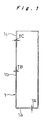
- Fig. 1 shows a cross-sectional view of this metal outer can 1.
- the bottom thickness (TA) of bottom portion 1a of this metal outer can 1 of cylindrical shape with a bottom shown in Fig. 1 is 0.4 mm, while the side thickness (TB) of side wall portion 1b is 0.18 mm, the ironing ratio being 55%. Also, the value of bottom thickness (TA)/side thickness (TB) is 2.22. It should be noted that the side thickness (TB) indicated here is the side thickness at intermediate height of metal outer can 1 and indicates a mean value of the side thickness.
- Metal outer can 1 was manufactured such that the side thickness at a position 5 mm below the aperture of the top 1c in metal outer can 1, constituting a portion in the vicinity of the sealing aperture (hereinbelow this is called the side thickness TC in the vicinity of the sealing aperture) was 0.2 mm i.e. about 11% thicker than the side thickness (TB) of the intermediate portion, with the object of increasing the strength of the sealing aperture.
- the HV value indicating the Vickers hardness of the nickel-plated steel sheet prior to processing of this metal outer can 1 was 108; the HV value of the side wall portion (1b) after formation of the metal outer can was 202; the HV value being thus increased 1.87 times by DI processing.
- a multiplicity of shallow grooves perpendicular to the bottom face are formed.
- This multiplicity of shallow grooves perpendicular to the bottom face in the battery inside face are the mold scratch marks in the DI can manufacturing step.
- Such scratch marks can be formed by introducing comparatively hard particles such as of alumina during DI processing.
- adopting the method of introducing alumina by mixing for example alumina particles in the plating bath in the nickel plating treatment step, the alumina particles that then become present in the plating in small amount can easily form a multiplicity of shallow grooves perpendicular to the bottom face.
- Fig. 3 and Fig. 4 show photographs taken using a scanning electron microscope showing this condition.
- Fig. 3 shows photographs taken with a scanning electron microscope in which the battery inside face of the metal outer can is magnified 300 times and in which the aperture region is further magnified 3000 times.
- the white longitudinal stripes in the photograph are the portions 7 of a multiplicity of shallow grooves perpendicular to the bottom face.
- Fig. 4 shows scanning electron microscope photographs of the cross-sectional surface of the metal outer can magnified 200 times and further of the aperture portion thereof magnified 10000 times; as shown by the photograph to a larger scale magnified 10000 times, in the nickel plating layer 8 of steel sheet SPCE material 9, a multiplicity of shallow grooves 7 of depth about 1 ⁇ m are formed in the battery inside face. In this way, manufacture of a metal outer can used in a battery according to the comparative example is completed.
- a cylindrical sealed nickel-hydrogen rechargeable battery was manufactured using the metal outer can manufactured as described above.
- the positive electrode and separator and negative electrode constituting the elements for electromotive-force were prepared.
- spherical nickel hydroxide powder and an additive such as zinc oxide, cobalt oxide, or cobalt hydroxide were mixed into the form of a paste, which was used to fill a sponge-like nickel conductive porous body, the electrode being constituted by forming to the prescribed dimensions (42 mm ⁇ 75 mm ⁇ 0.72 mm) by drying, pressurizing and cutting.
- Nickel metal leads were attached to this positive electrode plate such as to make it possible to connect with the positive electrode terminal of the battery.
- a paste was constituted by adding a conductive agent and/or bonding agent to alloy powder consisting of AB5 type MmNi 3.6 Mn 0.4 Al 0.3 Co 0.7 composition as a hydrogen-absorption alloy; this was applied on to a punching metal core member consisting of nickel-plated iron, and formed to the prescribed dimensions (42 mm ⁇ 101 mm ⁇ 0.44 mm) by drying, pressurizing and cutting, to constitute the electrode.
- the positive electrode and negative electrode were wound in spiral fashion with the separator in between and accommodated in the aforementioned metal outer can.
- the outermost periphery of the negative electrode 8 were arranged to directly contact the metal outer can.
- the positive electrode terminal constituted by the cap of the sealed battery was connected with the positive electrode plate by spot welding.
- 2.0 cc of an aqueous solution of potassium hydroxide (KOH) of specific gravity 1.30, in which was dissolved 40 g/l of lithium hydroxide (LiOH.H 2 O), constituting the electrolyte was introduced into the battery and a sealed battery was constituted by sealing the metal outer can and sealing cap by ordinary caulking sealing.
- KOH potassium hydroxide
- LiOH.H 2 O lithium hydroxide
- cell B was constructed using the aluminium-killed steel sheet directly without any nickel plating, but a multiplicity of shallow grooves perpendicular to the bottom face were formed in its surface.
- Cell C had a nickel layer but was of a construction in which the multiplicity of shallow grooves perpendicular to the bottom face were absent from its surface.
- the ironing ratio of this metal outer can was 12.5%, which was lower than that of the comparative example, with the result that the HV value of the side wall after formation of the metal-outer can was low, at 124, and could only be raised 1.15 times by processing.
- Cell D therefore differed from the comparative example not only in that the relationship of the bottom thickness/side thickness was outside the range of the comparative example but also in that the change of HV value produced by processing was less than 1.5 and in that the ironing ratio was less than 20%.
- Cell E was a battery employing carbon steel containing 0.11 wt.% carbon.
- Cell A according to the comparative example was of battery performance enabling it to be supplied as a nickel-hydrogen rechargeable battery and possessed excellent performance in respect of all of charging characteristic, discharge characteristic, cycle life characteristic, and storage characteristic; apart from this, it was a battery in which both the targeted high energy density of the battery and high reliability could be obtained simultaneously. More details concerning the performance of cell A will be given during the description of prior art cells B ⁇ E.
- Cell B was a battery in which the aluminium-killed steel sheet was used directly without nickel plating, but in which the metal outer can was subjected to formation of a multiplicity of shallow grooves perpendicular to the bottom face in its surface.
- drawing and ironing processing in the process of manufacturing the metal outer can did not necessarily proceed smoothly, and forming defects were found to be more easily produced than in the comparative example.
- cell C was of a construction wherein a nickel layer was provided but a multiplicity of shallow grooves perpendicular to the bottom face were not formed in the surface.
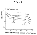
- a difference was found in comparison with cell A in respect of discharge characteristic, in particular the discharge voltage under high-rate discharge.
- Fig. 5 is a view showing a comparison of the characteristics under high-rate (1 CmA, 3 CmA) discharge at 20°C. As can be seen from Fig.
- cell D since the side wall of the metal outer can was processed to a thickness of 0.35 mm, although the HV value of the side wall was comparatively low, no problems occurred regarding the pressure withstanding strength. However, in the case of cell D, since its side thickness of 0.35 mm was about twice that of the comparative example, in which the side thickness was 0.18 mm, the effective volume within the battery was reduced by about 5%, with the result that the problem arose of a 5% drop of battery energy density.
- cell E was a battery using a metal outer can employing carbon steel of carbon content 0.11 wt.%.
- drawing and ironing working were difficult, making processing of the outer can difficult to perform.
- the material of the metal outer can is chiefly iron and which is constructed with a nickel layer provided on at least the battery inside face
- the material of the metal outer can is chiefly iron and which is constructed with a nickel layer provided on at least the battery inside face
- nickel-plated steel sheet of thickness 0.4 mm was employed, which was obtained by subjecting both sides of aluminium-killed steel sheet SPCE to nickel plating of about 3.5 micron, followed by heat treatment.
- This nickel plated steel sheet was first of all punched to rectangular shape and a metal can cup having a bottom was manufactured by drawing processing using a press. Little change in the bottom thickness and side thickness of this cup from those of the blank material was found.
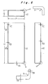
- this metal can cup having a bottom was introduced into a DI mold and a metal can having a bottom and having the external dimensions: width P 22 mm, height 52 mm and thickness Q 8 mm, was manufactured by continuous ironing processing. Since, in this condition, the upper parts of the sides (lugs) of the metal can having a bottom were not flat, but presented a somewhat distorted shape due to processing, the side upper parts were cropped to obtain a metal outer can 10 of height H 48 mm shown in Fig. 6.
- the bottom thickness (TA) of this metal outer can was 0.4 mm, while its side thickness (TB) was 0.2 mm, representing an ironing ratio of 50%. Also, the value of bottom thickness/side thickness was 2.0.
- the side thickness (TB) indicated here is the side thickness at intermediate height of metal outer can 10 and indicates a mean value of the side thickness.
- the metal outer can was manufactured such that the side thickness (TC; this will be termed the side thickness in the vicinity of the sealing aperture) at a position 5mm below the aperture at the top 10c which is the region in the vicinity of the sealing aperture in metal outer can 10 is about 25% thicker, at 0.25mm, than the side thickness (TB) of the intermediate portion, with the object of increasing sealing strength.
- TC side thickness
- TB side thickness
- the HV value indicating the Vickers hardness of the nickel plated steel sheet prior to processing this metal outer can was 108; the HV value indicating the Vickers hardness of the side wall portion 10b after molding of the metal outer can was 186; thus the HV value was increased 1.72 times by DI processing.
- a multiplicity of shallow grooves perpendicular to the bottom face are formed on the battery inside face in this DI can manufacturing step in which ironing processing is continuously performed.
- This multiplicity of shallow grooves perpendicular to the bottom face in the battery inside face are the mold scratch marks in the DI can manufacturing step.
- scratch marks can easily be formed by alumina particles.
- the radius R of the corner portions on the battery inside face produced by the metal mold in the DI can manufacturing step i.e. the corners present at the bottom face and the side face, and of the corners present between adjacent side faces is 0.4mm. This condition is shown with reference to the longitudinal cross-sectional view and transverse cross-sectional view in Fig. 6.
- a prismatic lithium ion secondary battery was manufactured using a metal outer can manufactured as above.
- First of all the positive electrode and separator and negative electrode constituting the elements for electromotive-force were prepared.
- LiCoO 2 , a conductive agent consisting of acetylene black, and a fluorine resin binder etc. were mixed into the form of a paste, which was applied to an aluminium foil plate, and formed to the desired dimensions by drying, pressurizing and cutting to constitute the electrode.
- a lead wire was attached to this positive electrode plate to make it possible to connect it with the positive electrode terminal.
- For the separator polyethylene porous film of thickness 0.027mm was employed.
- styrene butadiene rubber (SBR) adhesive and carboxymethyl cellulose (CMC) thickener were added to spherical graphite and applied to a copper foil substrate, and formed to the prescribed dimensions by drying, pressurizing and cutting to constitute the electrode.
- the positive electrode and negative electrode were wound in spiral fashion with the separator in between and accommodated in the aforementioned metal outer can.
- a cap portion constituting the positive electrode terminal of the sealed battery and the positive electrode plate were joined by an aluminium lead, and the negative electrode terminal of the metal outer can and the negative electrode plate were joined by a nickel lead.
- ethylene carbonate (EC) and diethyl carbonate (DEC) were blended in mol ratio 1:3 and used to dissolve lithium hexafluoro phosphate (LiPF 6 ) in a concentration of 1mol/l.
- This electrolyte was poured into the battery and the metal outer can and sealing cap were sealed by the ordinary laser sealing to constitute a sealed battery.
- This battery was of prismatic shape with width 22mm, height 48mm, thickness 8mm and the battery weight was about 18g.
- the battery had a capacity of 610mAh.
- This battery will be referred to as cell F according to the present invention.
- aluminium alloy sheet (3003) with manganese in solid solution was employed.
- Batteries such as cell G in which aluminium alloy is employed in the outer can of a lithium ion secondary battery currently hold the lime-light as batteries intended to have light weight, but, in order to ensure performance equivalent to that of cell F in regard to pressure withstanding strength, in the case of cell G, the side thickness of the metal can having a bottom must be at least 0.5mm and a side thickness of 0.5mm was therefore chosen.
- the external dimensions of this cell were made the same as cell F and the positive electrode, negative electrode, separator and electrolyte were made the same as those of cell F, the result was that the battery weight was about 18g and the battery capacity was 550mAh.
- cell F according to the present invention had a volume energy density of 260Wh/l and a weight energy density of 122Wh/kg; thus, in relation to the 234Wh/l and 110Wh/kg of cell G, it can be seen that cell F was much superior to the prior art cell G by 11% in terms of volume energy density and by 11% also in terms of weight energy density, respectively.
- the bottom thickness/side thickness of the metal outer can whose chief constituent is iron according to the present invention is specified as 1.5 ⁇ 7.0. It might be desirable to have a higher value in order to reduce size and weight but if the value is made high there are concerns regarding quality reliability and safety and as a result of several tests it was found that a range up to 7.0 is satisfactory. Also if this value is less than 1.5, the benefit in terms of raising battery energy density is insufficient. In particular it was found that this invention can be effectively practiced in a range of 2.5 ⁇ 5.0 of bottom thickness/side thickness.
- the iron-based blank material should be carbon steel for cold rolling containing 0.1%wt% or less of carbon (C), preferably carbon steel containing 0.1wt% or less of at least one of titanium (Ti) or niobium (Nb). It was ascertained that, in regard to the carbon content and ease of ironing processing, lowering the carbon content improves ease of processing, and furthermore if the steel is carbon steel containing 0.1wt% or less of at least one of titanium (Ti) or niobium (Nb), its ease of processing is increased.
- the metal outer can is of cylindrical shape with in particular an outer diameter of under 35 mm ⁇
- the side thickness (TC) in the vicinity of the battery sealing aperture is made at least 30% thicker than the side thickness (TB) in the other portions
- the benefits of the comparative example can further emphasized. This is because pressure withstanding strength can be comparatively satisfactorily maintained in batteries of cylindrical shape of external diameter under 35mm ⁇ or shape similar thereto even if the side thickness of the metal outer can is made quite thin. Rather the location where problems occur in such batteries in regard to pressure withstanding strength is the vicinity of the battery sealing aperture.
- the present invention can be applied apart from this to for example primary batteries such as alkali manganese dry batteries or lithium primary batteries, or polymer lithium batteries; in fact it can be applied to primary batteries or secondary batteries wherein the metal can is of prismatic shape or shape similar thereto, so long as they are batteries in which the elements for electromotive-force are accommodated in a metal outer can.
- primary batteries such as alkali manganese dry batteries or lithium primary batteries, or polymer lithium batteries
- the present invention thanks to the formation of a multiplicity of shallow grooves perpendicular to the bottom face in the surface of a nickel layer on the inside face of a battery metal outer can, the contact resistance of the metal outer can and the elements for electromotive-force that are accommodated therein can be greatly reduced. Also, it is greatly superior in corrosion resistance owing to the formation of this multiplicity of shallow grooves perpendicular to the bottom face solely in the nickel layer.
- a metal outer can made using a high ironing ratio is obtained, making it possible to reduce battery weight and overall thickness and as a result to achieve higher battery energy density.
- the present invention is therefore useful in achieving simultaneously both higher battery energy density and high reliability and safety.
Landscapes
- Chemical & Material Sciences (AREA)
- Chemical Kinetics & Catalysis (AREA)
- Electrochemistry (AREA)
- General Chemical & Material Sciences (AREA)
- Engineering & Computer Science (AREA)
- Mechanical Engineering (AREA)
- Inorganic Chemistry (AREA)
- Sealing Battery Cases Or Jackets (AREA)
- Secondary Cells (AREA)
Priority Applications (1)
| Application Number | Priority Date | Filing Date | Title |
|---|---|---|---|
| EP02011597A EP1246274B1 (en) | 1997-08-05 | 1998-08-03 | Battery and method of its manufacture |
Applications Claiming Priority (3)
| Application Number | Priority Date | Filing Date | Title |
|---|---|---|---|
| JP22428297 | 1997-08-05 | ||
| JP22428297A JP3604879B2 (ja) | 1997-08-05 | 1997-08-05 | 電池の製造方法 |
| PCT/JP1998/003465 WO1999008332A1 (en) | 1997-08-05 | 1998-08-03 | Battery and method of its manufacture |
Related Child Applications (1)
| Application Number | Title | Priority Date | Filing Date |
|---|---|---|---|
| EP02011597A Division EP1246274B1 (en) | 1997-08-05 | 1998-08-03 | Battery and method of its manufacture |
Publications (3)
| Publication Number | Publication Date |
|---|---|
| EP0971425A1 EP0971425A1 (en) | 2000-01-12 |
| EP0971425A4 EP0971425A4 (en) | 2000-08-16 |
| EP0971425B1 true EP0971425B1 (en) | 2004-03-17 |
Family
ID=16811336
Family Applications (2)
| Application Number | Title | Priority Date | Filing Date |
|---|---|---|---|
| EP98935349A Expired - Lifetime EP0971425B1 (en) | 1997-08-05 | 1998-08-03 | Battery case of prismatic shape and battery with increased energy density |
| EP02011597A Expired - Lifetime EP1246274B1 (en) | 1997-08-05 | 1998-08-03 | Battery and method of its manufacture |
Family Applications After (1)
| Application Number | Title | Priority Date | Filing Date |
|---|---|---|---|
| EP02011597A Expired - Lifetime EP1246274B1 (en) | 1997-08-05 | 1998-08-03 | Battery and method of its manufacture |
Country Status (8)
| Country | Link |
|---|---|
| US (1) | US6333124B1 (pl) |
| EP (2) | EP0971425B1 (pl) |
| JP (1) | JP3604879B2 (pl) |
| CN (2) | CN100502091C (pl) |
| DE (2) | DE69822448T2 (pl) |
| ID (1) | ID23985A (pl) |
| PL (1) | PL191768B1 (pl) |
| WO (1) | WO1999008332A1 (pl) |
Families Citing this family (38)
| Publication number | Priority date | Publication date | Assignee | Title |
|---|---|---|---|---|
| EP1202360A4 (en) * | 1999-05-07 | 2004-09-22 | Matsushita Electric Industrial Co Ltd | RECTANGULAR BATTERY CONTAINER AND MANUFACTURING METHOD THEREOF |
| JP3923259B2 (ja) * | 2000-08-22 | 2007-05-30 | 松下電器産業株式会社 | 電池の製造方法 |
| TW508860B (en) * | 2000-08-30 | 2002-11-01 | Mitsui & Amp Co Ltd | Paste-like thin electrode for battery, its manufacturing method, and battery |
| JP4853935B2 (ja) | 2000-09-01 | 2012-01-11 | 日立マクセルエナジー株式会社 | アルカリ乾電池 |
| US6946221B2 (en) * | 2000-12-26 | 2005-09-20 | Matsushita Electric Industrial Co., Ltd. | Square battery container, method of manufacturing the container, and square battery using the container |
| JP3694506B2 (ja) | 2003-02-04 | 2005-09-14 | 石崎プレス工業株式会社 | プレス加工を用いた電池用負極缶の製造方法 |
| JP2004326624A (ja) * | 2003-04-25 | 2004-11-18 | Aruze Corp | 識別センサ |
| JP4491208B2 (ja) * | 2003-08-29 | 2010-06-30 | パナソニック株式会社 | 電池缶およびその製造方法ならびに電池 |
| US20050079411A1 (en) * | 2003-10-08 | 2005-04-14 | Truelove & Maclean, Incorporated | Drawn and grooved battery can |
| JP4247831B2 (ja) * | 2003-11-27 | 2009-04-02 | 日立マクセル株式会社 | 密閉角形電池 |
| KR100561310B1 (ko) * | 2004-05-31 | 2006-03-15 | 삼성에스디아이 주식회사 | 리튬 폴리머 전지팩 및 코어팩과 케이스의 분리 방법 |
| JP5089861B2 (ja) * | 2004-12-15 | 2012-12-05 | 三星エスディアイ株式会社 | 蓄電デバイス及び蓄電デバイスの外装体の製造方法及び蓄電デバイスの外装体の成形装置 |
| JP4942365B2 (ja) * | 2006-02-28 | 2012-05-30 | 三洋電機株式会社 | 円筒形電池 |
| JP2010061892A (ja) * | 2008-09-02 | 2010-03-18 | M & G Eco Battery:Kk | 渦巻き電極群を有する二次電池 |
| JP5355012B2 (ja) | 2008-09-25 | 2013-11-27 | Fdkエナジー株式会社 | 電池缶及びアルカリ電池 |
| US20100323268A1 (en) * | 2009-06-19 | 2010-12-23 | White Box, Inc. | System and method for forming conductors of an energy generating device |
| CN102130309A (zh) * | 2010-01-12 | 2011-07-20 | 深圳市比克电池有限公司 | 一种锂离子电池钢壳、电池及其制造方法 |
| US20120028094A1 (en) * | 2010-07-27 | 2012-02-02 | Yongsam Kim | Battery pack |
| CN102169971A (zh) * | 2011-03-28 | 2011-08-31 | 慈晟 | 一种电池的金属壳体及其制备方法 |
| CN102290539A (zh) * | 2011-08-02 | 2011-12-21 | 深圳市豪鹏科技有限公司 | 电池壳生产工艺及电池壳 |
| US9876198B2 (en) * | 2012-12-18 | 2018-01-23 | Samsung Sdi Co., Ltd. | Rechargeable battery |
| KR101440893B1 (ko) * | 2012-12-18 | 2014-09-17 | 삼성에스디아이 주식회사 | 이차 전지 |
| JP6030178B2 (ja) * | 2014-09-18 | 2016-11-24 | 株式会社神戸製鋼所 | 車載電池用の角形電池ケースおよびその製造方法 |
| KR101621253B1 (ko) * | 2015-10-21 | 2016-05-16 | 공병인 | 2차 전지 케이스의 제조방법 |
| KR102484264B1 (ko) * | 2015-11-24 | 2023-01-02 | 삼성에스디아이 주식회사 | 이차 전지 및 그의 제조 방법 |
| DE102016121089A1 (de) * | 2016-11-04 | 2018-05-09 | Schuler Pressen Gmbh | Verfahren und Vorrichtung zur Herstellung eines prismatischen Batteriezellenbehälters |
| JP6610514B2 (ja) * | 2016-11-21 | 2019-11-27 | トヨタ自動車株式会社 | リチウムイオン二次電池 |
| PL3648192T3 (pl) * | 2017-10-23 | 2025-11-24 | Lg Energy Solution, Ltd. | Sposób wytwarzania cylindrycznej obudowy akumulatora mającej zmniejszoną chropowatość powierzchni |
| CN108393396A (zh) * | 2018-03-07 | 2018-08-14 | 江西双华实业发展有限公司 | 电池钢壳制造方法 |
| JP7610419B2 (ja) * | 2021-01-28 | 2025-01-08 | 大和製罐株式会社 | 角形電池缶の製造方法 |
| EP4513634A4 (en) * | 2022-06-10 | 2025-07-23 | Contemporary Amperex Technology Co Ltd | BATTERY CELL, BATTERY AND ELECTRICAL APPLIANCE |
| KR20250163988A (ko) * | 2023-04-03 | 2025-11-21 | 스페이라 게엠베하 | Co2 배출량이 적은 원통형 배터리 셀 하우징 |
| KR20250163987A (ko) * | 2023-04-03 | 2025-11-21 | 스페이라 게엠베하 | Co2 배출량이 낮은 각기둥형 배터리 셀 하우징 |
| DE102023204802A1 (de) | 2023-05-23 | 2024-11-28 | Fraunhofer-Gesellschaft zur Förderung der angewandten Forschung eingetragener Verein | Verfahren zur Herstellung eines metallischen Gehäuses |
| WO2024259692A1 (zh) | 2023-06-21 | 2024-12-26 | 宁德时代新能源科技股份有限公司 | 电池单体、电池、用电装置及储能装置 |
| WO2025151015A1 (ko) * | 2024-01-12 | 2025-07-17 | 주식회사 엘지에너지솔루션 | 탄소강 소재, 고강도 금속 캔 및 이에 수용된 이차전지 |
| CN117977072B (zh) * | 2024-02-04 | 2025-09-05 | 蜂巢能源科技股份有限公司 | 电芯壳体、电芯及电池包 |
| CN223977972U (zh) * | 2024-12-30 | 2026-03-06 | 惠州亿纬锂能股份有限公司 | 扣式壳体结构及扣式电池 |
Family Cites Families (18)
| Publication number | Priority date | Publication date | Assignee | Title |
|---|---|---|---|---|
| JPH0799686B2 (ja) * | 1984-02-28 | 1995-10-25 | 松下電器産業株式会社 | 電 池 |
| JP2563185B2 (ja) * | 1987-10-08 | 1996-12-11 | 東芝電池株式会社 | 角形密閉電池 |
| JPH01313848A (ja) * | 1988-06-10 | 1989-12-19 | Matsushita Electric Ind Co Ltd | 角形密閉電池およびその電池容器の製法 |
| JPH02150660A (ja) | 1988-11-30 | 1990-06-08 | Toshiba Corp | 温風暖房機 |
| JPH02150660U (pl) * | 1989-05-24 | 1990-12-27 | ||
| US5576113A (en) * | 1993-06-04 | 1996-11-19 | Katayama Special Industries, Ltd. | Battery can, sheet for forming battery can, and method for manufacturing sheet |
| JP3282887B2 (ja) * | 1993-06-17 | 2002-05-20 | 東洋鋼鈑株式会社 | 深絞り性、溶接性に優れた薄鋼板およびその製造方法 |
| JP2785237B2 (ja) | 1993-09-28 | 1998-08-13 | キヤノン株式会社 | 無線通信装置 |
| WO1995011527A1 (fr) * | 1993-10-22 | 1995-04-27 | Toyo Kohan Co., Ltd. | Feuille d'acier traite en surface pour boitier de batterie et boitier de batterie produit a l'aide de ladite feuille |
| JP3599391B2 (ja) * | 1994-12-09 | 2004-12-08 | 東芝電池株式会社 | 角形電池の製造方法 |
| JP3247570B2 (ja) * | 1995-03-17 | 2002-01-15 | 松下電器産業株式会社 | 電池缶の製造方法 |
| JP3096615B2 (ja) * | 1995-06-02 | 2000-10-10 | 三洋電機株式会社 | アルミニウム外装缶の二次電池 |
| JP3402047B2 (ja) * | 1996-02-08 | 2003-04-28 | 松下電器産業株式会社 | 電 池 |
| US6126759A (en) * | 1996-02-08 | 2000-10-03 | Nkk Corporation | Steel sheet for 2-piece battery can having excellent formability, anti secondary work embrittlement and corrosion resistance |
| TW338071B (en) * | 1996-05-09 | 1998-08-11 | Toyo Koban Kk | A battery container and surface treated steel sheet for battery container |
| JP3625008B2 (ja) * | 1997-04-04 | 2005-03-02 | 東芝電池株式会社 | アルカリ電池 |
| US6040082A (en) * | 1997-07-30 | 2000-03-21 | Medtronic, Inc. | Volumetrically efficient battery for implantable medical devices |
| US6001504A (en) * | 1998-03-11 | 1999-12-14 | Duracell Inc. | Prismatic battery housing |
-
1997
- 1997-08-05 JP JP22428297A patent/JP3604879B2/ja not_active Expired - Lifetime
-
1998
- 1998-08-03 DE DE69822448T patent/DE69822448T2/de not_active Expired - Lifetime
- 1998-08-03 DE DE69837291T patent/DE69837291T2/de not_active Expired - Lifetime
- 1998-08-03 CN CNB2006101728187A patent/CN100502091C/zh not_active Expired - Lifetime
- 1998-08-03 WO PCT/JP1998/003465 patent/WO1999008332A1/ja not_active Ceased
- 1998-08-03 EP EP98935349A patent/EP0971425B1/en not_active Expired - Lifetime
- 1998-08-03 EP EP02011597A patent/EP1246274B1/en not_active Expired - Lifetime
- 1998-08-03 US US09/254,365 patent/US6333124B1/en not_active Expired - Lifetime
- 1998-08-03 CN CNB988011131A patent/CN1324721C/zh not_active Expired - Lifetime
- 1998-08-03 PL PL332741A patent/PL191768B1/pl not_active IP Right Cessation
-
1999
- 1999-08-03 ID IDW990146D patent/ID23985A/id unknown
Also Published As
| Publication number | Publication date |
|---|---|
| EP0971425A4 (en) | 2000-08-16 |
| EP0971425A1 (en) | 2000-01-12 |
| PL332741A1 (en) | 1999-10-11 |
| PL191768B1 (pl) | 2006-06-30 |
| EP1246274A2 (en) | 2002-10-02 |
| DE69837291T2 (de) | 2007-11-15 |
| US6333124B1 (en) | 2001-12-25 |
| DE69837291D1 (de) | 2007-04-19 |
| EP1246274B1 (en) | 2007-03-07 |
| DE69822448D1 (de) | 2004-04-22 |
| ID23985A (id) | 2000-06-14 |
| JP3604879B2 (ja) | 2004-12-22 |
| CN1324721C (zh) | 2007-07-04 |
| JPH1154095A (ja) | 1999-02-26 |
| CN1236491A (zh) | 1999-11-24 |
| DE69822448T2 (de) | 2006-01-26 |
| EP1246274A3 (en) | 2004-01-14 |
| WO1999008332A1 (en) | 1999-02-18 |
| CN100502091C (zh) | 2009-06-17 |
| CN1983671A (zh) | 2007-06-20 |
Similar Documents
| Publication | Publication Date | Title |
|---|---|---|
| EP0971425B1 (en) | Battery case of prismatic shape and battery with increased energy density | |
| EP0944119B1 (en) | Battery and method of manufacturing the same | |
| CN100426558C (zh) | 电池壳及其制造方法和使用它的电池 | |
| JP3857818B2 (ja) | リチウムイオン二次電池 | |
| EP1183742B1 (en) | Lithium secondary battery and method of manufacturing the same | |
| US7087345B2 (en) | Spirally-rolled electrodes with separator and the batteries therewith | |
| JP3630992B2 (ja) | 電池及びその電池缶の製造方法 | |
| JP3846154B2 (ja) | 電池缶及びその製造方法と電池 | |
| US20250316812A1 (en) | Secondary battery | |
| US20260066399A1 (en) | Secondary battery and method of manufacturing the same | |
| KR100462128B1 (ko) | 전지용 나선형 전극군, 전지 및 전지용 전극 | |
| JP2003109554A (ja) | 密閉型電池 | |
| JP2000113862A (ja) | 角形アルカリ二次電池 |
Legal Events
| Date | Code | Title | Description |
|---|---|---|---|
| PUAI | Public reference made under article 153(3) epc to a published international application that has entered the european phase |
Free format text: ORIGINAL CODE: 0009012 |
|
| 17P | Request for examination filed |
Effective date: 19990426 |
|
| AK | Designated contracting states |
Kind code of ref document: A1 Designated state(s): DE FR GB |
|
| A4 | Supplementary search report drawn up and despatched |
Effective date: 20000705 |
|
| AK | Designated contracting states |
Kind code of ref document: A4 Designated state(s): DE FR GB |
|
| 17Q | First examination report despatched |
Effective date: 20020124 |
|
| RTI1 | Title (correction) |
Free format text: BATTERY CASE OF PRISMATIC SHAPE AND BATTERY WITH INCREASED ENERGY DENSITY |
|
| GRAP | Despatch of communication of intention to grant a patent |
Free format text: ORIGINAL CODE: EPIDOSNIGR1 |
|
| RTI1 | Title (correction) |
Free format text: BATTERY CASE OF PRISMATIC SHAPE AND BATTERY WITH INCREASED ENERGY DENSITY |
|
| RTI1 | Title (correction) |
Free format text: BATTERY CASE OF PRISMATIC SHAPE AND BATTERY WITH INCREASED ENERGY DENSITY |
|
| GRAA | (expected) grant |
Free format text: ORIGINAL CODE: 0009210 |
|
| GRAS | Grant fee paid |
Free format text: ORIGINAL CODE: EPIDOSNIGR3 |
|
| AK | Designated contracting states |
Kind code of ref document: B1 Designated state(s): DE FR GB |
|
| REG | Reference to a national code |
Ref country code: GB Ref legal event code: FG4D |
|
| REF | Corresponds to: |
Ref document number: 69822448 Country of ref document: DE Date of ref document: 20040422 Kind code of ref document: P |
|
| ET | Fr: translation filed | ||
| PLBE | No opposition filed within time limit |
Free format text: ORIGINAL CODE: 0009261 |
|
| STAA | Information on the status of an ep patent application or granted ep patent |
Free format text: STATUS: NO OPPOSITION FILED WITHIN TIME LIMIT |
|
| 26N | No opposition filed |
Effective date: 20041220 |
|
| PGFP | Annual fee paid to national office [announced via postgrant information from national office to epo] |
Ref country code: GB Payment date: 20120801 Year of fee payment: 15 |
|
| PGFP | Annual fee paid to national office [announced via postgrant information from national office to epo] |
Ref country code: FR Payment date: 20120823 Year of fee payment: 15 |
|
| GBPC | Gb: european patent ceased through non-payment of renewal fee |
Effective date: 20130803 |
|
| REG | Reference to a national code |
Ref country code: FR Ref legal event code: ST Effective date: 20140430 |
|
| PG25 | Lapsed in a contracting state [announced via postgrant information from national office to epo] |
Ref country code: GB Free format text: LAPSE BECAUSE OF NON-PAYMENT OF DUE FEES Effective date: 20130803 |
|
| PG25 | Lapsed in a contracting state [announced via postgrant information from national office to epo] |
Ref country code: FR Free format text: LAPSE BECAUSE OF NON-PAYMENT OF DUE FEES Effective date: 20130902 |
|
| PGFP | Annual fee paid to national office [announced via postgrant information from national office to epo] |
Ref country code: DE Payment date: 20170725 Year of fee payment: 20 |
|
| REG | Reference to a national code |
Ref country code: DE Ref legal event code: R071 Ref document number: 69822448 Country of ref document: DE |