EP0970814B1 - Printing method and printing apparatus - Google Patents
Printing method and printing apparatus Download PDFInfo
- Publication number
- EP0970814B1 EP0970814B1 EP99305069A EP99305069A EP0970814B1 EP 0970814 B1 EP0970814 B1 EP 0970814B1 EP 99305069 A EP99305069 A EP 99305069A EP 99305069 A EP99305069 A EP 99305069A EP 0970814 B1 EP0970814 B1 EP 0970814B1
- Authority
- EP
- European Patent Office
- Prior art keywords
- ink
- density
- printing
- inks
- discharge
- Prior art date
- Legal status (The legal status is an assumption and is not a legal conclusion. Google has not performed a legal analysis and makes no representation as to the accuracy of the status listed.)
- Expired - Lifetime
Links
Images


Classifications
-
- H—ELECTRICITY
- H04—ELECTRIC COMMUNICATION TECHNIQUE
- H04N—PICTORIAL COMMUNICATION, e.g. TELEVISION
- H04N1/00—Scanning, transmission or reproduction of documents or the like, e.g. facsimile transmission; Details thereof
- H04N1/40—Picture signal circuits
- H04N1/40087—Multi-toning, i.e. converting a continuous-tone signal for reproduction with more than two discrete brightnesses or optical densities, e.g. dots of grey and black inks on white paper
-
- B—PERFORMING OPERATIONS; TRANSPORTING
- B41—PRINTING; LINING MACHINES; TYPEWRITERS; STAMPS
- B41J—TYPEWRITERS; SELECTIVE PRINTING MECHANISMS, i.e. MECHANISMS PRINTING OTHERWISE THAN FROM A FORME; CORRECTION OF TYPOGRAPHICAL ERRORS
- B41J2/00—Typewriters or selective printing mechanisms characterised by the printing or marking process for which they are designed
- B41J2/005—Typewriters or selective printing mechanisms characterised by the printing or marking process for which they are designed characterised by bringing liquid or particles selectively into contact with a printing material
- B41J2/01—Ink jet
- B41J2/205—Ink jet for printing a discrete number of tones
- B41J2/2056—Ink jet for printing a discrete number of tones by ink density change
Definitions
- This invention relates to a printing method and printing apparatus and, more particularly, to a printing method and printing apparatus for printing an image on a printing medium using a printhead according to an inkjet printing method.
- Printing units incorporated in printers, copying machines, facsimile apparatuses, and the like print an image consisting of a dot pattern on a printing medium such as a paper sheet or thin plastic plate on the basis of image information.
- Such printing apparatuses are classified according to their printing methods into an inkjet type, wire dot type, thermal type, laser beam type, and the like.
- the inkjet type (inkjet printing apparatus) is designed to print an image by discharging ink (printing solution) droplets from the orifices of a printhead and adhering them to a printing medium.
- One of these inkjet printing apparatuses employs a printhead having an array of a plurality of orifices to realize high printing speed, and another one of these inkjet printing apparatuses employs a plurality of printheads in correspondence with the number of types of color inks in order to be capable of color printing.
- half-tone processing methods such as a dither method and error diffusion method are used in these inkjet printing apparatuses as methods of faithfully reproducing the tonality of image information.
- a printing apparatus when a printing apparatus has a high resolution (1,000 dots/inch or more), excellent multi-level printing can be performed. If, however, a printing apparatus has a low resolution (about 360 to 720 dots/inch), the printed dots of a highlight portion of a formed image become conspicuous, and the discontinuity of pixels tends to increase the graininess of a formed image.
- the voltage, the pulse width, or the like to be applied to a printhead is controlled to modulate the diameter of each print dot adhered to a printing medium, thereby attaining tonality.
- the minimum size of a printable dot according to this method is put into practical use for representing several tonality levels.
- a density modulation method is also available, in which the density of dots within a predetermined dot matrix (a predetermined area) is changed while the dot size remains the same.
- this method requires a considerably large area to increase the number of representable tonality levels, and hence the resolution decreases.
- EP-A-0 606 022 discloses an ink jet recording method for recording on a recording medium by discharging ink from discharge openings of a recording head, utilising plural inks of different densities of the same color.
- suction means and pressurizing means are used to remove undesirable substances and bubbles from liquid paths by forcibly drawing ink from the nozzles of the printhead.
- ink coagulations near orifices are removed by cleaning the ink discharge surfaces with a wiper.
- the orifice surfaces of the printhead are wiped at a predetermined timing.
- preliminary discharge which differs from ink discharge for printing, is performed at a predetermined timing. With this operation, fresh ink is always supplied into each nozzle to perform stable printing. In this way, recovery operation is done.
- the tonality balance deteriorates with an increase in ink density, and the tonality continuity loses smoothness.
- pseudo outlines appears on a printed image, and the quality deteriorates in some case.
- EP-A-0 942 585 which is prior art under Art. 54(3) EPC only, discloses an image processing method and apparatus in which ink is discharged from an inkjet printhead using a plurality of inks having different densities, which comprises an input step of inputting image data, a calculation step of calculating a lapse time from a previous ink discharge, a prediction step of predicting a density change of ink according to a time variation of ink based on the lapse time calculated at the calculation step, a selection step of selecting a type of ink suitable for representing a density value indicated by the input image data based on the density change of ink predicted at said prediction step; and a driving step of driving the printhead so as to cause ink discharge from the printhead based on the type of ink selected at the selection step.
- a printing method of performing printing on a printing medium by discharging ink from an inkjet printhead using a plurality of inks having different densities comprising: an input step of inputting multi-valued image data; characterised by further comprising a calculation step of calculating a lapse time from previous ink discharge by the printhead; a prediction step of predicting a printing density change of ink according to a time variation of ink based on the lapse time calculated at the calculation step; a selection step of selecting a type of ink and ink discharge amount per single discharge operation suitable for representing a density value indicated by the input multi-valued image data based on the printing density change of ink predicted at the prediction step; and the driving step of driving the printhead so as to cause ink discharge from the printhead based on the type of ink and ink discharge amount selected at the selection step.
- the selection step preferably includes a step of selecting a type of ink to be discharged based on the multi-valued image data and a step of changing a discharge amount of the selected type of ink in accordance with the predicted density change.
- droplets of a plurality of types of inks having different densities can be discharged to the substantially same pixel position of the printing medium.
- the prediction step preferably uses a characteristic change table storing the relationship between the lapse time and ink density change.
- the characteristic change table may be prepared for each of a plurality of inks having different densities, and may be rewritable.
- a plurality of printheads can be used in correspondence with the plurality of inks having. different densities.
- the selection step can comprise selecting the type of ink and an ink discharge amount for each pixel subjected to printing.
- the plurality of inks having different densities are inks of the same color.
- the printing method desirably further comprises the pseudo half-tone step of performing pseudo half-tone processing such as an error diffusion method in order to represent a density value indicated by the input multivalued image data.
- a printing apparatus for performing printing on a printing medium by discharging ink from an inkjet printhead using a plurality of inks having different densities, comprising: input means for inputting multivalued image data, characterised by further comprising calculation means for calculating a lapse time from previous ink discharge by the printhead; prediction means for predicting a printing density change of ink according to a time variation of ink based on the lapse time calculated by the calculation means; selection means for selecting a type of ink and ink discharge amount per single discharge operation suitable for representing a density value indicated by the input multi-valued image data based on the printing density change of ink predicted by the prediction means; and driving means for driving the printhead so as to cause ink discharge from the printhead based on the type of ink and ink discharge amount selected by the selection means.
- the apparatus preferably includes means for selecting a type of ink to be discharge based on the multi-valued image data and means for changing a discharge amount of the selected type of ink in accordance with the predicted density change.
- the printing apparatus using the printing method preferably comprises the following aspects in addition to the above-described preferred aspects of the printing method.
- the printhead comprises a plurality of nozzles for discharging ink
- each of the plurality of nozzles comprises an electrothermal transducer for generating heat energy in order to discharge ink by the heat energy
- each of the plurality of nozzles comprises a plurality of electrothermal transducers for changing an ink discharge amount from each of the plurality of nozzles.
- a table showing the relationship between a density value represented by the input multi-valued image data, and a representable density value by a combination of inks having different densities is referred.
- the foregoing object is attained by providing a computer-readable memory which stores a program for executing printing processing of performing printing on a printing medium by discharging ink from an inkjet printhead using a plurality of inks having different densities, the program comprising: codes for executing input processing of inputting multi-valued image data, and characterised by further comprising codes for executing calculation processing of calculating a lapse time from previous ink discharge by the printhead; codes for executing prediction processing of predicting a printing density change of ink according to a time variation of ink based on the lapse time calculated in the calculation processing; codes for executing selection processing of selecting a type of ink and ink discharge amount per single discharge operation suitable for representing a density value indicated by the input multi-valued image data based on the printing density change of ink predicted in prediction processing; and codes for executing driving processing of driving the printhead so as to cause ink discharge from the printhead based on the type of ink and ink discharge amount selected
- a lapse time from previous ink discharge by the printhead is calculated, a density change of ink according to the lapse time is predicted based on the calculated lapse time, a type of ink and ink discharge amount suitable for representing a density value indicated by input multi-valued image data are selected based on the predicted density change of ink, and the printhead is driven so as to cause ink discharge from the printhead based on the selected type of ink and ink discharge amount.
- the invention is particularly advantageous since, even when printing is performed using ink which is left in the printhead for a while and changes in density, the changed density can be corrected by using another ink having a different density or changing the ink discharge amount. As a result, a high-quality image can be printed.
- An ink/film system having an additive property is a system in which when a transmission image is to be printed on a transparent film using an inkjet printer, if ink is overlaid a plurality of number of times at the same pixel position, the density of the pixel increases.
- the number of tonality levels can be greatly increased by overlaying a plurality of inks having different densities at the same pixel position.
- the number of representable tonality levels can be maximized by changing the combination of inks D1, D2, D3, and D4 to be discharged with the ratio of the densities of the respective inks being set to 1 : 2 : 4 : 8.
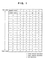
- Fig. 1 is a table showing an example of the contents of an ink distribution table representing the relationship between the density value of image data and the ink discharge.
- This embodiment can perform two-step ink discharge with ink discharge amounts of 40 pl or 20 pl from each nozzle in one discharge operation by the printhead of the inkjet printer.
- the ink discharge amount will be described in detail later.
- reference symbols d1 to d4 denote signals indicating the presence/absence of discharge of the inks D1 to D4.
- Each of these signals d1 to d4 is a ternary signal indicating "large droplet discharge” for "2", “small droplet discharge” for "1”, or “not discharge” for "0". If, for example, the density value of image data is "10”, the discharged inks D2 and D4 are overlaid at the same pixel position.
- image data showing sixteen (16) density levels can be represented from "0" to "15" with continuous density by combining the presence/absence of discharge of these inks.
- the number of tonality levels per pixel can be set to the maximum number, i.e., 2 n , by combining inks represented by density ratios of 1 : 2 : ⁇ : 2 i-1 : ⁇ : 2 n-1 .
- the ink discharge amount will be explained next.
- the ink discharge amount adhered to one pixel and the transmission density are proportional to each other.
- Fig. 2 is a graph showing the relationship between the ink discharge amount and transmission density in the ink/film system.
- the ink discharge amount and transmission density are proportional to each other. It has been confirmed by experiment that the proportional relationship between the ink discharge amount and transmission density substantially holds in the transmission density range of 0 to 2.5D.
- the number of representable tonality levels can be increased by changing the ink discharge amount.
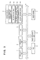
- Fig. 3 is a block diagram showing the functional arrangement of an inkjet printer according to a representative embodiment of the present invention.
- reference numeral 1 denotes an image input unit such as a scanner; 2, an operation unit having various keys for setting various parameters and designating a print start; and 3, a CPU for controlling the overall apparatus by executing various control programs.
- Reference numeral 4 denotes a storage medium, such as a ROM, FD (Floppy Disk), CD-ROM, HD (Hard Disk), memory card, and magneto-optical disk, that stores control programs and error processing programs for operating this apparatus. All the operations of the apparatus according to this embodiment are based on the execution of these programs.
- the storage medium 4 includes a gamma correction conversion table 4a to be referred to in gamma conversion processing, an ink distribution table 4b to be referred to in ink distribution processing to be described later, a table 4c, showing the increase rate of an ink density with respect to a lapse of a non-ink-discharge period, to be referred to during multi-level processing and ink distribution processing, and a control program group 4d corresponding to various programs.
- Reference numeral 5 denotes a RAM that serves as a work area used when the CPU 3 executes various programs stored in the storage medium 4, a temporary saving area in error processing, and a work area used in executing image processing. After the various tables in the storage medium 4 are copied to the RAM 5, the CPU 3 can change the contents of the tables to perform image processing while referring to the changed tables.
- Reference numeral 6 denotes an image processing unit for generating a discharge pattern for realizing multi-level representation by the inkjet method on the basis of input image data; 7, a printer unit (printer engine) for forming a dot image on the basis of the discharge pattern generated by the image processing unit 6 in printing operation; and 8, a bus line for transmitting address signals, data, control signals, and the like among the components of the apparatus.
- the image processing unit can adopt two conceivable arrangements.
- the two arrangements are one not using the error diffusion method for multi-valued representation of an image, and one using the error diffusion method.
- Fig. 4A is a block diagram showing the detailed functional arrangement of the image processing unit 6.
- an image signal CV input from the image input unit 1 is converted into a signal CD indicating a density in a gamma correction processor 11 using the gamma correction conversion table 4a.
- the obtained density signal CD is stored in a page memory area of the image processing work area in the RAM 5.
- a target pixel selector 12 selects one pixel (target pixel) from the signal CD stored in the page memory area to obtain the density value.
- An ink distribution processor 13 refers to the ink distribution table 4b on the basis of the density value of the target pixel to select an ink combination candidate for representing the density of the target pixel.
- a density increase correction processor 14 calculates the non-use time of each nozzle used for discharging ink, and predicts a specific variation in the density obtained by the ink combination selected by the ink distribution processor 13 with respect to the ideal density by referring to the ink density increase table 4c, which is linearly approximated by the least squares method.
- the pulse waveform of a head driving signal for discharging ink is changed, as needed, to determine the optimal density combination, i.e., ternary signals d1, d2, d3, and d4 for driving the printhead to discharge ink (for determining "large droplet discharge", "small droplet discharge", or "not discharge”).
- the above processing is repeated for all pixels on the basis of the density value of image data, thereby generating ternary signals d1, d2, d3, and d4 for respective pixels having different densities.
- reference numerals 17-1, 17-2, 17-3, and 17-4 denote delay circuits for adjusting the timings of discharging four types of inks for adhering and overlaying them to the same pixel position.
- Fig. 4B is a block diagram showing the detailed functional arrangement of the image processing unit 6.
- an image signal CV input from the image input unit 1 is converted into a signal CD indicating a density in a gamma correction processor 11 using the gamma correction conversion table 4a.
- the obtained density signal CD is stored in a page memory area of the image processing work area in the RAM 5.
- a target pixel selector 12 selects one pixel (target pixel) from the signal CD stored in the page memory area to obtain the density value.
- An ink distribution processor 13 refers to the ink distribution table 4b on the basis of the density value of the target pixel to select an ink combination candidate for representing the density of the target pixel.
- a density increase correction processor 14 calculates the non-use time of each nozzle used for discharging ink, and predicts a specific variation in the density obtained by the ink combination selected by the ink distribution processor 13 with respect to the ideal density by referring to the ink density increase table 4c, which is linearly approximated by the least squares method.
- the pulse waveform of a head driving signal for discharging ink is changed, as needed, to determine the optimal density combination, i.e., ternary signals d1, d2, d3, and d4 for driving the printhead to discharge ink (for determining "large droplet discharge", "small droplet discharge", or "not discharge”).
- a density error calculation unit 15 calculates the difference between a representable density from the ink combination determined by the density increase correction processor 14 in accordance with the additive property and the density value of the target pixel.
- An error diffusion processor 16 diffuses the difference calculated by the density error calculation unit 15 to neighboring pixels in the page memory area in accordance with diffusion coefficients.
- the above processing is repeated for all pixels on the basis of the density value of image data, thereby generating ternary signals d1, d2, d3, and d4 for respective pixels having different densities.
- reference numerals 17-1, 17-2, 17-3, and 17-4 denote delay circuits for adjusting the timings of discharging four types of inks for adhering and overlaying them to the same pixel position.
- the printer engine 7 uses four printheads corresponding to four types of inks, and discharges the inks from the orifice arrays of corresponding printheads in accordance with the ternary signals d1, d2, d3, and d4 to form a multi-level image.
- Fig. 5 is a plan view showing the detailed arrangement of the printer engine 7.
- printheads 21 are mounted on a carriage 20.
- the printheads 21-1 to 21-4 have orifice arrays for discharging inks.
- the orifice arrays of the printheads 21-1 to 21-4 are arranged at predetermined intervals.
- Inks to nozzle arrays corresponding to the printheads 21-1 to 21-4 are respectively supplied from four ink cartridges 22-1 to 22-4.
- the ink cartridges 22-1 to 22-4 are ink cartridges for respectively supplying the inks D1, D2, D3, and D4. The densities of these inks will be described later.
- the four ink cartridges are generically referred to as ink cartridges 22.
- Controls signals and the like to the printhead 21 are sent through a flexible cable 23.
- a printing medium 24 such as printing paper, film, or thin plastic plate is held by a paper discharge roller 25 through a convey roller (not shown) and conveyed in the direction indicated by the arrow in accordance with driving of a convey motor 26.
- the carriage 20 is guided and supported by a guide shaft 27 and linear encoder 28.
- the carriage 20 reciprocates along the guide shaft 27 through a driving belt 29 according to driving of a carriage motor 30.
- Two heating elements for generating heat energy for ink discharge are arranged inside (liquid paths) the orifices of the printhead 21 described above.
- the printhead 21 drives, on the basis of a print signal, the two heating elements at the same time for "large droplet discharge” of ink and one of them for "small droplet discharge” of ink in accordance with the read timing of the linear encoder 28 to discharge ink droplets onto the printing medium in the order of the inks D1, D2, D3, and D4 and adhere the droplets thereto, thereby forming an image.
- a recovery unit 32 having a cap unit 31 is provided at the home position of the carriage 20 which is set outside the print area.
- the cap unit 31 includes four caps 31-1 to 31-4 in correspondence with the number of printheads. While printing is not performed, the carriage 20 is moved to the home position, and the caps 31-1 to 31-4 of the cap unit 31 close the orifices of the corresponding printheads 21-1 to 21-4, thereby preventing the respective printheads from clogging up due to the coagulation of ink upon evaporation of the ink solvent or the adhesion of undesirable substances such as dust.
- the capping function of the cap unit 31 is used to prevent orifices exhibiting low printing frequencies from causing discharge failures or clogging by performing idling discharge operation, i.e., discharging ink to the cap unit 31 situated at some distance from the orifices, or is used to perform discharge recovery operation for orifices that have caused discharge failures by driving a pump (not shown) to draw ink from the orifices while the orifices are capped.
- Reference numeral 33 denotes an ink accepter used to accept preliminary discharged inks immediately before the printheads 21-1 to 21-4 perform printing operation. That is, preliminary discharge is performed toward the ink accepter 33 when the printheads 21-1 to 21-4 pass over the ink accepter 33.
- a blade and wiping member are provided near the cap unit 31 so as to clean the orifice formation surface of the printhead 21.
- the detailed arrangement of the inkjet printhead having at least two heating elements capable of independently receiving signals and being driven, and a method, applicable to the present invention, of performing multi-level printing by modulating, in accordance with the tonality value, the input timings of signals input to the heating elements will be explained.
- Fig. 17 is a cross sectional view of a liquid path in the printhead 21.
- a liquid path 59 filled with liquid is formed by combining a member 62 with a member 63 with a groove having a predetermined width by glue such that the groove is covered with the member 62.
- the member 62 consist of a base board 54 made of glass or the like, a heat sink layer 55 provided on the base board 54 and electrothermal transducers 50-1, 50-2 provided on the heat sink layer 55.
- An orifice 57 is formed at the end of the liquid path 59.
- Surface portions ( ⁇ L), in contact with ink in the liquid path 59, of the electrothermal transducers 50-1 and 50-2 and the adjacent portion serve as a thermal acting portion. Due to heat generated by the electrothermal transducers 50-1 and 50-2 in accordance with an input signal, liquid in this thermal acting portion is subject to a sudden state change. In other word, the liquid is evaporated so as to create a bubble. This bubble causes an ink droplet 58 to be discharge from the orifice.
- Liquid is supplied from a liquid reservoir 60 to the liquid path 59 through a tube 61.
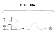
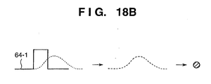
- Figs. 18A and 18B conceptually show the relationship among a signal inputted to the electrothermal transducers 50-1 and 50-2, a bubble volume and an amount (a size) of a discharged ink droplet.
- a solid line indicates a pulse signal showing an electric power supplied to the electrothermal transducers 50-1 and 50-2
- a broken line indicates the change of the bubble volume according to the heat generated by the electrothermal transducers 50-1 and 50-2.
- Fig. 18A shows a case where pulses 64-1 and 64-2 are concurrently applied to the electrothermal transducers 50-1 and 50-2, respectively. In this case, the volume of a created bubble is large and the size (amount) of discharged ink droplet is large.
- Fig. 18B shows a case where only a pulse 64-1 is applied to the electrothermal transducer 50-1. In this case, the volume of a created bubble is small and the size (amount) of discharged ink droplet is small.
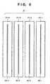
- Fig. 6 is a view showing the printhead 21 when viewed from the orifice formation surface side.
- reference numerals 40-1 to 40-4 denote orifice arrays for discharging the inks D1 to D4 in correspondence with the printheads 21-1 to 21-4.
- each orifice array has 256 orifices with a 600-dot pitch per inch (600 dpi).
- the orifice arrays 40-1 to 40-4 can discharge and overlay four types of inks D1 to D4 in the conveyance direction (subscanning direction) of the printing medium while the carriage 20 is scanned once. As a result, a multi-level image can be formed without prolonging the print time.
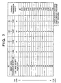
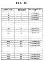
- Fig. 7 is a table showing the contents of the ink distribution table representing discharge/non-discharge of the inks D1, D2, D3, and D4 with respect to an 8-bit image signal level per pixel.
- Fig. 7 shows the transmission densities of the inks D1, D2, D3, and D4, and the overlaid transmission density for the combination of these inks.
- the image signal level represents the density value, with a smaller value representing a lower density and a larger value representing a higher density.
- the transmission density of a transparent film as a printing medium is set to 0D.
- the transmission densities of the inks D1, D2, D3, and D4 are expressed by the transmission densities obtained when printing is done over a predetermined area on the printing medium by discharging these inks using the inkjet printer in this embodiment.
- the density ratio of the inks D1, D2, D3, and D4 is 1 : 2 : 4 : 8, as described above.
- the table in Fig. 7 shows a case wherein an 8-bit image signal per pixel is expressed by 16 tonality levels from 0D to 2.4D.
- Fig. 8 is a graph showing the ink density increase rate with respect to the lapse of the non-discharge period of ink.
- the abscissa represents the non-discharge time of ink; and the ordinate, the increase rate of the transmission density of ink.
- a change shown in Fig. 8 is obtained by linearly approximating representative densities by the least squares method on the basis of experimental results.
- the "non-discharge time" is the time interval between a time when an ink droplet is discharged from one nozzle of the printhead 21 and a time when ink is discharged next.
- ink is discharged from the nozzle array of the printhead 21 at a frequency of 10 kHz.
- the ink density increases about 70% if no ink is discharged even once during scanning of the carriage 20 over a short side of an A3 printing sheet (about 0.7 sec).
- An increase in ink density during scanning for printing operation results from the evaporation of the ink solvent at each nozzle tip. Once the ink whose density has increased at a nozzle tip is discharged as an ink droplet, fresh ink is refilled into the nozzle tip. Then, the density at the nozzle tip returns to the specified density before the density increase.
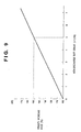
- Fig. 9 is a graph showing the ink density increase rate (dD) expressed by the non-discharge dot count at a discharge frequency of 10 kHz with respect to the non-discharge time on the abscissa in Fig. 8.
- an increase in ink density is predicted based on the non-discharge history by referring to the density increase graph in processing of generating ternary signals each having one of three values: "large droplet discharge”, “small droplet discharge”, or “not discharge”.
- the ink density is corrected by the increase amount, thereby printing an image free from any density increase.
- the ink density increase table is generated on the basis of changes shown in Fig. 9 so as to allow the CPU of the inkjet printer to easily refer to an ink density increase.
- the generated table is stored in the storage medium 4 such as a ROM.
- the ink density increase rate is 150%.
- the ink density increase table will be described on the basis of this graph.
- Fig. 10 is a graph showing the contents of the ink density increase table (characteristic change table).
- these contents are stored in the area of the ink density increase table 4c in the storage medium 4.
- the calculation results of the density increase rate (dD) shown in Fig. 9 are written in the density increase table shown in Fig. 10 in correspondence with the non-discharge count (N). By writing the calculation results in the table in advance, the calculation amount in real-time image processing can be reduced, resulting in an increase in processing speed. If the density increase rate (dD) for each non-discharge dot count (N) is expressed by 4-byte data, the address offset of the ink density increase table which can be accessed every byte is expressed by 4 bytes.
- the non-discharge count (N) corresponds to an address offset, and can be made to correspond to the address by multiplying the non-discharge count (N) by four.
- This value (4 x N) is added to the base address in the ink density increase table. The contents at the address are read out to obtain a density increase rate.
- this ink density at the corresponding time can be predicted by multiplying this increase rate by the basic ink density to be obtained.
- FIGs. 11A and 11B are schematic views showing a part of the printer engine 7 shown in Fig. 5 which concerns printing in the carriage moving direction (main scanning direction).
- Fig. 11A is a side view of this portion, and
- Fig. 11B is a view showing the printing medium 24 when viewed from above.
- the carriage 20, on which the printhead 21 is mounted starts to move from the home position (not shown) in the direction indicated by an arrow S.
- the carriage 20 reaches a constant speed when the printhead 21 passes over the ink accepter 33.
- the printheads 21-1, 21-2, 21-3, and 21-4 pass over the ink accepter 33 in the order named and performs preliminary discharge toward the ink accepter 33 at a position A.
- the printhead 21 can print an image in an area between B-C of the printing medium 24.
- Figs. 11A and 11B printing starts from a position D.
- the printhead 21 can print an image in an area having a width E - F on the printing medium 24 in one scanning operation of the carriage, and can print an image in an area having a width F - G in the next scanning operation.
- ink is discharged from the nozzle array of the printhead 21 of this apparatus at a frequency of 10 kHz, and the print density in the main scanning direction is 600 dpi.
- the main scanning speed of the carriage 20 is therefore about 423.3 mm/sec.
- the printhead reaches the print start position D at 0.5 sec after the preliminary discharge at the main scanning speed, and starts printing in accordance with a generated discharge pattern.
- ink is discharged by this printing start, ink whose density has increased at the nozzle tip of the printhead is discharged as an ink droplet, and the ink density at the nozzle tip is restored to the normal value.
- the density increase rate of each of the inks D1, D2, D3, and D4 exhibits the characteristics shown in Figs. 8 and 9 in application of ink densities and overlaid transmission densities corresponding to the density values of an image signal set in the ink distribution table shown in Fig. 7, and the ink density at the nozzle tip is restored to the normal value immediately after preliminary discharge at the position A on the ink accepter 33 shown in Fig. 11A. Then, the density of the nozzle tip increases by about 50% at the print start position D because the carriage 20 requires 0.5 sec to move from the position A to position D.
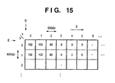
- Fig. 12 is a table showing an example of the density signal level of image data stored in the page memory area in the image processing work area of the RAM 5 in order to print an image on the printing medium 24 shown in Figs. 11A and 11B.
- Reference symbols shown in Fig. 12 correspond to those in Figs. 11A and 11B, and one square in Fig. 12 corresponds to one pixel of an image printed at a resolution of 600 dpi.
- this image is formed by repeating similar patterns such as two pixels having a density value "100" in the main scanning direction (S direction), one pixel having a density value "90", six pixels having a density value "0", and again two pixels having a density value "100". In the subscanning direction, pixels having the same value continue.
- the ink density increases by 0.01%. If, however, a change in image data value shown in Fig. 12, i.e., the number of non-discharged pixels is about 10 pixels in the main scanning direction, the density increase rate is about 0.1% at most. For the sake of descriptive simplicity, therefore, an increase in ink density will be neglected.
- the transmission densities of the inks D1, D2, D3, and D4 used alone correspond to "17”, “34", “68", and "136" at the image density signal level, respectively.
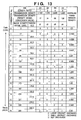
- Fig. 13 is a table which is obtained by adding multivalued error diffusion thresholds and values corresponding to the image density signal levels of transmission densities of inks to the table shown in Fig. 7.
- each pixel row in the main scanning direction corresponds to one nozzle of the printhead.
- an arbitrary pixel is indicated by (x, y) with x and y respectively indicating the horizontal and vertical directions.
- a pixel (0, 0) indicates the pixel at the upper left of the matrix.
- the density signal level of the pixel (0, 0) is "100" in Fig. 12.
- a combination of "large droplet discharge” by the ink D2 and “large droplet discharge” by the ink D3, which is indicated by the combination number No. 6, is selected as a candidate.
- the ink densities of both the inks D2 and D3 have increased by 50%. It can be predicted from this that the transmission density of the ink D2 has increased from "34" to "51", and the transmission density of the ink D3 has increased from "68" to "102". With the combination of "large droplet discharge” by the ink D2 and “large droplet discharge” by the ink D3, therefore, the density becomes "153" which is higher than target density "102" by about 50%.
- the density signal level of the ideal combination is "102"
- the density signal level "100" of the pixel (0, 0) is to be expressed. Since the ink density of both the inks D2 and D3 have increased, it is inappropriate that ink is discharged in accordance with the contents of the threshold table. Thus, the ink D3 is set to "small droplet discharge” under the control of this embodiment. As a result, the ink discharge amount of the ink D3 is halved from 40 pl to 20 pl to decrease the transmission density.
- the predicted density of "large droplet discharge” by the ink D2 becomes "51”
- the predicted density of "small droplet discharge” by the ink D3 becomes "51”
- the predicted density of this discharge combination becomes "102".
- the ink combination determined in this manner is stored as a ternary signal pattern indicating "large droplet discharge”, “small droplet discharge”, or “not discharge” of each ink at an address in a corresponding one of memories Md1, Md2, Md3, and Md4 defined in the RAM 5 in correspondence with the pixel (0, 0).
- the processing for the target pixel (0, 0) is terminated with the above operation, and the ternary signals d1, d2, d3, and d4 for the pixel (0, 0) are determined.
- the pixel (1, 0) is set as the next target pixel.
- the density signal level of this pixel (1, 0) is "100" as shown in Fig. 12.
- the combination No. 6 of "large droplet discharge” by the ink D2 and “large droplet discharge” by the ink D3 is selected as a candidate by referring to the threshold table shown in Fig. 13.
- the inks selected from the threshold table shown in Fig. 13 are the inks D2 and D3, and their densities have been restored to the normal values.
- the transmission density is "34" for "large droplet discharge” by the ink D2 and “68” for "large droplet discharge” by the ink D3. Consequently, the transmission density becomes “102” from the combination of "large droplet discharge” by the ink D2 and “large droplet discharge” by the ink D3.
- This combination is suitable for representing density signal level "100" of the pixel (1, 0), so that "large droplet discharge” by the inks D2 and D3 is determined.
- the ink combination determined in this manner is stored as a ternary signal pattern indicating "large droplet discharge”, “small droplet discharge”, or “not discharge” of each ink at an address of each of the memories Md1, Md2, Md3, and Md4 defined in the RAM 5 in correspondence with the pixel (1, 0).
- the pixel (2, 0) is set as the next target pixel.
- the density signal level of this pixel (2, 0) is "90" as shown in Fig. 12. Based on this value, the combination No. 5 of "large droplet discharge” by the ink D1 and “large droplet discharge” by the ink D3 is selected as a candidate by referring to the threshold table shown in Fig. 13. Since the inks D2 and D3 have been discharged for printing of the pixel (1, 0), the densities of the inks D2 and D3 are restored to the normal values. In contrast to this, the densities of the remaining inks (inks D1 and D4) have been increased by 50% since they are not discharged after preliminary discharge.
- the transmission density is "25.5" for "large droplet discharge” by the ink D1 and “68” for "large droplet discharge” by the ink D3.
- the transmission density of this combination is predicted to be "93.5". This predicted value reaches a predetermined threshold, so ink discharge according to the contents of the threshold table is inappropriate.
- discharge by the ink D1 is set to "small droplet discharge” under the control of this embodiment.
- the ink discharge amount of the ink D1 is halved from 40 pl to 20 pl to decrease the transmission density to "12.25”.
- the predicted density as the combination of the predicted density of "small droplet discharge” by the ink D1 and the predicted density of "large droplet discharge” by the ink D3 becomes "80.25".
- the ink combination determined in this manner is stored as a ternary signal pattern indicating "large droplet discharge”, “small droplet discharge”, or “not discharge” of each ink at an address in each of the memories Md1, Md2, Md3, and Md4 defined in the RAM 5 in correspondence with the pixel (2, 0).
- the above processing is repeated for the sequentially selected target pixels in the main scanning direction (S) on the basis of the density signal level of image data.
- the ternary signals d1, d2, d3, and d4 are generated for each pixel using the four inks having different densities.
- These ternary signals d1, d2, d3, and d4 are stored at the addresses in the memories Md1, Md2, Md3, and Md4 in correspondence with each pixel.
- the first pixel, i.e., pixel (0, 1) on the next line is set as the next target pixel, and similar processing is executed in the main scanning direction.
- processing is started on the basis of a prediction that the density of each ink has increased by 50% at the target pixel (0, 1).
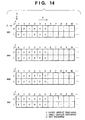
- Fig. 14 is a table showing ternary signal values generated by the above processing that are stored in the memories Md1, Md2, Md3, and Md4.
- ternary signals indicating "large droplet discharge”, “small droplet discharge”, or “not discharge” of each of the inks D1, D2, D3, and D4 are respectively stored in the memories Md1, Md2, Md3, and Md4.
- "x/y" at the upper left end of each memory matrix means “x/y” shown in Fig. 12, and each memory matrix corresponds to that in Fig. 12.
- Fig. 15 is a table showing the state of the density distribution when an input image density signal shown in Fig. 12 is actually used for printing by changing the combination of inks on the basis of the basic ink distribution table shown in Fig. 7 or 13. As is apparent from Fig. 15, an abrupt density increase at an image print start point, e.g., at the left end in Fig. 15 is suppressed.
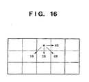
- Fig. 16 shows an example of how weighting is performed to distribute an error in a target pixel to neighboring pixels in multivalued error diffusion processing executed in this embodiment.
- reference symbol "*" denotes a target pixel.
- the difference error between the representable density level by a combination of four inks and the image density signal level is distributed to neighboring pixels in accordance with the error distribution coefficients shown in Fig. 16.
- the density signal level of the pixel (0, 0) is "100" in Fig. 12.
- a combination of "large droplet discharge” by the ink D2 and “large droplet discharge” by the ink D3, which is indicated by the combination number No. 6, is selected as a candidate.
- the ink densities of both the inks D2 and D3 have increased by 50%. It can be predicted from this that the transmission density of the ink D2 has increased from "34" to "51", and the transmission density of the ink D3 has increased from "68" to "102". With the combination of "large droplet discharge” by the ink D2 and “large droplet discharge” by the ink D3, therefore, the density becomes "153" which is higher than target density "102" by about 50%.
- the density signal level of the ideal combination is "102"
- the density signal level "100" of the pixel (0, 0) is to be expressed. Since the ink density of both the inks D2 and D3 have increased, it is inappropriate that ink is discharged in accordance with the contents of the threshold table. Thus, the ink D3 is set to "small droplet discharge” under the control of this embodiment. As a result, the ink discharge amount of the ink D3 is halved from 40 pl to 20 pl to decrease the transmission density.
- the predicted density of "large droplet discharge” by the ink D2 becomes "51”
- the predicted density of "small droplet discharge” by the ink D3 becomes "51”
- the predicted density of this discharge combination becomes "102".
- the ink combination determined in this manner is stored as a ternary signal pattern indicating "large droplet discharge”, “small droplet discharge”, or “not discharge” of each ink at an address in a corresponding one of memories Md1, Md2, Md3, and Md4 defined in the RAM 5 in correspondence with the pixel (0, 0).
- the difference error is difference "-2" obtained by subtracting predicted representable density "102" from image density signal level "100" of the pixel (0, 0). This difference is distributed to the neighbouring pixels of the target pixel in accordance with the error distribution coefficients in Fig. 14 such that "-8/8" is distributed to the pixel (1, 0), and "-6/8" is distributed to the pixel (0, 1).
- the distributed errors are added to the respective neighboring pixels in this manner, the density signal level of the pixel (1, 0) is changed to "99", and the density signal level of the pixel (0, 1) is changed to "99.25".
- the processing for the target pixel (0, 0) is terminated with the above operation, and the ternary signals d1, d2, d3, and d4 for the pixel (0, 0) are determined.
- the pixel (1, 0) is set as the next target pixel.
- the density signal level of this pixel (1, 0) has become “99” by error diffusion from the pixel (0, 0) described above.
- the combination No. 6 of "large droplet discharge” by the ink D2 and “large droplet discharge” by the ink D3 is selected as a candidate by referring to the threshold table shown in Fig. 13.
- the inks selected from the threshold table shown in Fig. 13 are the inks D2 and D3, and their densities have been restored to the normal values.
- the transmission density is "34" for "large droplet discharge” by the ink D2 and “68” for "large droplet discharge” by the ink D3. Consequently, the transmission density becomes “102” from the combination of "large droplet discharge” by the ink D2 and “large droplet discharge” by the ink D3.
- This combination is suitable for representing density signal level "99" of the pixel (1, 0), so that "large droplet discharge” by the inks D2 and D3 is determined.
- the ink combination determined in this manner is stored as a ternary signal pattern indicating "large droplet discharge”, “small droplet discharge”, or “not discharge” of each ink at an address of each of the memories Md1, Md2, Md3, and Md4 defined in the RAM 5 in correspondence with the pixel (1, 0).
- the difference error is difference "-3" obtained by subtracting predicted representable density value "102" from image density signal level "99" of the pixel (1, 0).
- This difference is distributed to the neighboring pixels in accordance with the error distribution coefficients in Fig. 14 such that "-12/8" is distributed to the pixel (2, 0), “-9/8” is distributed to the pixel (1, 1), and "-3/8” is distributed to the pixel (0, 1).
- These distributed errors are respectively added to the pixels (2, 0), (1, 1), and (0, 1) around the target pixel.
- the pixel (2, 0) is set as the next target pixel.
- the density signal level of this pixel (2, 0) has become "88.5" by error diffusion from the pixel (1, 0). Based on this value, the combination No. 5 of "large droplet discharge” by the ink D1 and “large droplet discharge” by the ink D3 is selected as a candidate by referring to the threshold table shown in Fig. 13. Since the inks D2 and D3 have been discharged for printing of the pixel (1, 0), the densities of the inks D2 and D3 are restored to the normal values. In contrast to this, the densities of the remaining inks (inks D1 and D4) have been increased by 50% since they are not discharged after preliminary discharge.
- the transmission density is "25.5" for "large droplet discharge” by the ink D1 and “68” for "large droplet discharge” by the ink D3.
- the transmission density of this combination is predicted to be "93.5". This predicted value reaches the threshold of error diffusion processing, so ink discharge according to the contents of the threshold table is inappropriate.
- discharge by the ink D1 is set to "small droplet discharge” under the control of this embodiment.
- the ink discharge amount of the ink D1 is halved from 40 pl to 20 pl to decrease the transmission density to "12.25”.
- the predicted density as the combination of the predicted density of "small droplet discharge” by the ink D1 and the predicted density of "large droplet discharge” by the ink D3 becomes "80.25".
- the ink combination determined in this manner is stored as a ternary signal pattern indicating "large droplet discharge”, “small droplet discharge”, or “not discharge” of each ink at an address in each of the memories Md1, Md2, Md3, and Md4 defined in the RAM 5 in correspondence with the pixel (2, 0).
- the difference error is difference "-8.25” obtained by subtracting image density signal level "88.5" of the pixel (2, 0) from predicted density value "80.25".
- This difference is distributed to the neighboring pixels in accordance with the error distribution coefficients shown in Fig. 14 such that "-33/8" is distributed to the pixel (3, 0), “-24.75/8” is distributed to the pixel (2, 1), and "-8.25/8" is distributed to the pixel (1, 1).
- These errors are then added to these neighboring pixels (3, 0), (2, 1), and (1, 1).
- the above processing is repeated for the sequentially selected target pixels in the main scanning direction (S) on the basis of the density signal level of image data.
- the ternary signals d1, d2, d3, and d4 are generated for each pixel using the four inks having different densities.
- These ternary signals d1, d2, d3, and d4 are stored at the addresses in the memories Md1, Md2, Md3, and Md4 in correspondence with each pixel.
- the first pixel, i.e., pixel (0, 1) on the next line is set as the next target pixel, and similar processing is executed in the main scanning direction.
- processing is started on the basis of a prediction that the density of each ink has increased by 50% at the target pixel (0, 1).
- an ink density increase is predicted by obtaining a lapse time from previous ink discharge using a preliminary discharge position, preliminary discharge time, and the density distribution on a formed image based on input image data. Discharging ink having a proper density is controlled on the basis of the predicted value. Thus, even if the ink density in the nozzle changes from the original density owing to the absence of ink discharge for a while, the density change is compensated by using another ink having a different density or changing the ink discharge amount. As a result, a high-quality image free from any density unevenness can be printed.
- one density increase table (characteristics change table) is referred to for the density of each ink.
- a plurality of ink increase tables may be prepared for different density increase rates due to different ink densities, or different density increase tables (characteristics change tables) may be prepared for respective inks.
- an ink density change over time is a density increase.
- the density change is not limited to the density increase as far as the density change indicates ink density change characteristics.
- a rewritable storage medium such as the RAM 5 is selected as the storage location of the density increase table (characteristics change table) described in the above embodiment, flexibility can be further enhanced.
- the combination of inks is changed on the basis of the ink distribution table formed based on inks before an ink density increase, i.e., inks which have not changed in density yet.
- the ink distribution table of the standard ink density adopts an algorithm of always discharging an ink having the highest standard density, an increase in OD value by an ink density increase can be suppressed to reduce image distortion.
- the ink D4 is not used unless the density signal level is equal to or more than "136", but is used at density signal level "68" or more in consideration of "small droplet discharge" of the ink. Therefore, for an ink density increase of 50%, the OD value of the ink D4 most greatly changes. For this reason, the ink D4 is desirably used as often as possible.
- a signal to the printhead having, in the nozzle, at least two heating elements capable of independently receiving signals is inputted, and an ink discharge amount is modulated in accordance with a tonality value.
- the present invention is not limited to this and can be applied to any printhead not having two heating elements in each nozzle so long as the printhead can modulate the ink discharge amount by changing the pulse waveform of a printhead driving signal.
- the present invention can also be applied to a printer apparatus of another printing method.
- a printer using a heating head such as a sublimation printer
- continuous printing operation raises the temperature of the printhead to increase the density of a printed image.
- the density increase table (characteristics change table) described in the above embodiment is replaced with the relationship between the print duty and density increase, a print density increase can be predicted to perform corresponding correction.
- a printer which comprises means (e.g., an electrothermal transducer, laser beam generator, and the like) for generating heat energy as energy utilized upon execution of ink discharge, and causes a change in state of an ink by the heat energy, among the ink-jet printers.
- means e.g., an electrothermal transducer, laser beam generator, and the like
- heat energy as energy utilized upon execution of ink discharge
- the system is effective because, by applying at least one driving signal, which corresponds to printing information and gives a rapid temperature rise exceeding film boiling, to each of electrothermal transducers arranged in correspondence with a sheet or liquid channels holding a liquid (ink), heat energy is generated by the electrothermal transducer to effect film boiling on the heat acting surface of the printhead, and consequently, a bubble can be formed in the liquid (ink) in one-to-one correspondence with the driving signal.
- the driving signal is applied as a pulse signal, the growth and shrinkage of the bubble can be attained instantly and adequately to achieve discharge of the liquid (ink) with the particularly high response characteristics.
- signals disclosed in U.S. Patent Nos. 4,463,359 and 4,345,262 are suitable. Note that further excellent printing can be performed by using the conditions described in U.S. Patent No. 4,313,124 of the invention which relates to the temperature rise rate of the heat acting surface.
- the arrangement using U.S. Patent Nos. 4,558,333 and 4,459,600 which disclose the arrangement having a heat acting portion arranged in a flexed region is also included in the present invention.
- the present invention can be effectively applied to an arrangement based on Japanese Patent Laid-Open Publication No. 59-123670 which discloses the arrangement using a slot common to a plurality of electrothermal transducers as a discharge portion of the electrothermal transducers, or Japanese Patent Laid-Open Publication No. 59-138461 which discloses the arrangement having an opening for absorbing a pressure wave of heat energy in correspondence with a discharge portion.
- a full line type printhead having a length corresponding to the width of a maximum printing medium which can be printed by the printer
- either the arrangement which satisfies the full-line length by combining a plurality of printheads as disclosed in the above specification or the arrangement as a single printhead obtained by forming printheads integrally can be used.
- a cartridge type printhead in which an ink tank is integrally arranged on the printhead itself but also an exchangeable chip type printhead, as described in the above embodiment, which can be electrically connected to the apparatus main unit and can receive an ink from the apparatus main unit upon being mounted on the apparatus main unit can be applicable to the present invention.
- recovery means for the printhead, preliminary auxiliary means, and the like provided as an arrangement of the printer of the present invention since the printing operation can be further stabilized.
- examples of such means include, for the printhead, capping means, cleaning means, pressurization or suction means, and preliminary heating means using electrothermal transducers, another heating element, or a combination thereof. It is also effective for stable printing to provide a preliminary discharge mode which performs discharge independently of printing.
- a printing mode of the printer not only a printing mode using only a primary color such as black or the like, but also at least one of a multicolor mode using a plurality of different colors or a full-color mode achieved by color mixing can be implemented in the printer either by using an integrated printhead or by combining a plurality of printheads.
- the ink is a liquid.
- the present invention may employ an ink which is solid at room temperature or less and softens or liquefies at room temperature, or an ink which liquefies upon application of a use printing signal, since it is a general practice to perform temperature control of the ink itself within a range from 30°C to 70°C in the ink-jet system, so that the ink viscosity can fall within a stable discharge range.
- an ink which is solid in a non-use state and liquefies upon heating may be used.
- an ink which liquefies upon application of heat energy according to a printing signal and is discharged in a liquid state, an ink which begins to solidify when it reaches a printing medium, or the like, is applicable to the present invention.
- an ink may be situated opposite electrothermal transducers while being held in a liquid or solid state in recess portions of a porous sheet or through holes, as described in Japanese Patent Laid-Open Publication No. 54-56847 or 60-71260.
- the above-mentioned film boiling system is most effective for the above-mentioned inks.
- the ink-jet printer of the present invention may be used in the form of a copying machine combined with a reader, and the like, or a facsimile apparatus having a transmission/reception function in addition to an image output terminal of an information processing equipment such as a computer.
- the present invention can be applied to a system constituted by a plurality of devices (e.g., host computer, interface device, reader, printer etc.) or to an apparatus comprising a single device (e.g., copy machine, facsimile etc.).
- a system constituted by a plurality of devices (e.g., host computer, interface device, reader, printer etc.) or to an apparatus comprising a single device (e.g., copy machine, facsimile etc.).
- the object of the present invention can be also achieved by providing a storage medium storing program codes for performing the aforesaid processes to a system or an apparatus, reading the program codes with a computer (e.g., CPU, MPU) of the system or apparatus from the storage medium, then executing the program.
- a computer e.g., CPU, MPU
- the program codes read from the storage medium realize the functions according to the embodiment, and the storage medium storing the program codes constitutes the invention.
- the storage medium such as a floppy disk, a hard disk, an optical disk, a magneto-optical disk, CD-ROM, CD-R, a magnetic tape, a non-volatile type memory card, and ROM can be used for providing the program codes.
- the present invention includes a case where an OS (operating system) or the like working on the computer performs a part or entire processes in accordance with designations of the program codes and realizes functions according to the above embodiment.
- the present invention also includes a case where, after the program codes read from the storage medium are written in a function expansion card which is inserted into the computer or in a memory provided in a function expansion unit which is connected to the computer, CPU or the like contained in the function expansion card or unit performs a part or entire process in accordance with designations of the program codes and realizes functions of the above embodiment.
Landscapes
- Physics & Mathematics (AREA)
- Discrete Mathematics (AREA)
- General Physics & Mathematics (AREA)
- Engineering & Computer Science (AREA)
- Multimedia (AREA)
- Signal Processing (AREA)
- Particle Formation And Scattering Control In Inkjet Printers (AREA)
- Fax Reproducing Arrangements (AREA)
- Ink Jet (AREA)
Applications Claiming Priority (4)
| Application Number | Priority Date | Filing Date | Title |
|---|---|---|---|
| JP18302898 | 1998-06-29 | ||
| JP18302898 | 1998-06-29 | ||
| JP17466899A JP3839996B2 (ja) | 1998-06-29 | 1999-06-21 | 記録方法及びその記録装置 |
| JP17466899 | 1999-06-21 |
Publications (3)
| Publication Number | Publication Date |
|---|---|
| EP0970814A2 EP0970814A2 (en) | 2000-01-12 |
| EP0970814A3 EP0970814A3 (en) | 2001-01-10 |
| EP0970814B1 true EP0970814B1 (en) | 2003-08-20 |
Family
ID=26496200
Family Applications (1)
| Application Number | Title | Priority Date | Filing Date |
|---|---|---|---|
| EP99305069A Expired - Lifetime EP0970814B1 (en) | 1998-06-29 | 1999-06-28 | Printing method and printing apparatus |
Country Status (4)
| Country | Link |
|---|---|
| US (1) | US6443548B1 (enExample) |
| EP (1) | EP0970814B1 (enExample) |
| JP (1) | JP3839996B2 (enExample) |
| DE (1) | DE69910502T2 (enExample) |
Families Citing this family (9)
| Publication number | Priority date | Publication date | Assignee | Title |
|---|---|---|---|---|
| JP3663919B2 (ja) * | 1998-06-26 | 2005-06-22 | セイコーエプソン株式会社 | 印刷装置および印刷方法並びに記録媒体 |
| JP3870046B2 (ja) * | 2000-08-31 | 2007-01-17 | キヤノン株式会社 | 記録装置及び記録方法 |
| US6666538B2 (en) * | 2001-07-30 | 2003-12-23 | Konica Corporation | Recording method of medical image and apparatus for recording medical image |
| JP4890693B2 (ja) * | 2001-08-10 | 2012-03-07 | キヤノン株式会社 | インクジェット記録装置 |
| JP4954494B2 (ja) * | 2004-05-06 | 2012-06-13 | オセ−テクノロジーズ ビーブイ | 欠陥印刷素子のカムフラージを用いた印刷方法 |
| KR100622368B1 (ko) * | 2005-06-10 | 2006-09-13 | 삼성전자주식회사 | 노즐 에러 보상 방법 및 이 방법이 적용되는 화상형성장치 |
| EP1935659B1 (en) * | 2006-12-21 | 2009-11-11 | Agfa Graphics N.V. | Inkjet printing methods and inkjet ink sets |
| JP2010234551A (ja) * | 2009-03-30 | 2010-10-21 | Fujifilm Corp | 画像形成装置 |
| JP2021069993A (ja) * | 2019-10-31 | 2021-05-06 | キヤノン株式会社 | ウルトラファインバブル生成装置およびその制御方法 |
Family Cites Families (16)
| Publication number | Priority date | Publication date | Assignee | Title |
|---|---|---|---|---|
| CA1127227A (en) | 1977-10-03 | 1982-07-06 | Ichiro Endo | Liquid jet recording process and apparatus therefor |
| JPS5936879B2 (ja) | 1977-10-14 | 1984-09-06 | キヤノン株式会社 | 熱転写記録用媒体 |
| US4330787A (en) | 1978-10-31 | 1982-05-18 | Canon Kabushiki Kaisha | Liquid jet recording device |
| US4345262A (en) | 1979-02-19 | 1982-08-17 | Canon Kabushiki Kaisha | Ink jet recording method |
| US4463359A (en) | 1979-04-02 | 1984-07-31 | Canon Kabushiki Kaisha | Droplet generating method and apparatus thereof |
| US4313124A (en) | 1979-05-18 | 1982-01-26 | Canon Kabushiki Kaisha | Liquid jet recording process and liquid jet recording head |
| US4558333A (en) | 1981-07-09 | 1985-12-10 | Canon Kabushiki Kaisha | Liquid jet recording head |
| JPS59123670A (ja) | 1982-12-28 | 1984-07-17 | Canon Inc | インクジエツトヘツド |
| JPS59138461A (ja) | 1983-01-28 | 1984-08-08 | Canon Inc | 液体噴射記録装置 |
| JPS6071260A (ja) | 1983-09-28 | 1985-04-23 | Erumu:Kk | 記録装置 |
| US4746935A (en) | 1985-11-22 | 1988-05-24 | Hewlett-Packard Company | Multitone ink jet printer and method of operation |
| US4860026A (en) * | 1987-06-25 | 1989-08-22 | Canon Kabushiki Kaisha | Halftone image recording method using recording data having a plurality of concentrations for one color |
| EP0707966B1 (en) | 1990-10-04 | 2000-02-02 | Canon Kabushiki Kaisha | Image recording apparatus for recording using a recording head |
| ATE214529T1 (de) | 1993-01-08 | 2002-03-15 | Canon Kk | Aufzeichnungsverfahren zur gradationsaufzeichnung mit hell- und dunkelfarbigen tinten und gerät dafür |
| US5734391A (en) * | 1993-12-28 | 1998-03-31 | Canon Kabushiki Kaisha | Printing system |
| JP4018286B2 (ja) | 1998-03-11 | 2007-12-05 | キヤノン株式会社 | インクジェット記録方法及び装置及び記録システム |
-
1999
- 1999-06-21 JP JP17466899A patent/JP3839996B2/ja not_active Expired - Fee Related
- 1999-06-24 US US09/339,380 patent/US6443548B1/en not_active Expired - Lifetime
- 1999-06-28 EP EP99305069A patent/EP0970814B1/en not_active Expired - Lifetime
- 1999-06-28 DE DE69910502T patent/DE69910502T2/de not_active Expired - Lifetime
Also Published As
| Publication number | Publication date |
|---|---|
| DE69910502T2 (de) | 2004-06-17 |
| JP2000079709A (ja) | 2000-03-21 |
| DE69910502D1 (de) | 2003-09-25 |
| JP3839996B2 (ja) | 2006-11-01 |
| US6443548B1 (en) | 2002-09-03 |
| EP0970814A3 (en) | 2001-01-10 |
| EP0970814A2 (en) | 2000-01-12 |
Similar Documents
| Publication | Publication Date | Title |
|---|---|---|
| US6439683B1 (en) | Image processing method and apparatus and recording apparatus | |
| US7438374B2 (en) | Inkjet printing apparatus, printing control method for inkjet printing apparatus, program, and storage medium | |
| JP4298127B2 (ja) | 画像記録方法、画像記録装置、該画像記録装置の制御方法、コンピュータ可読記憶媒体及び画像処理方法 | |
| KR100242783B1 (ko) | 큰 도트 및 작은 도트를 사용하는 기록 방법 | |
| US6942310B2 (en) | Ink-jet printing method and apparatus | |
| EP0851385A2 (en) | Multi-pass recording system using random mask | |
| US6572212B2 (en) | Ink-jet printer and control method and apparatus for the same | |
| JPH0946522A (ja) | 画像処理方法、プリント装置および表示装置 | |
| KR19990014017A (ko) | 잉크 젯 인쇄 장치 및 방법 | |
| JP2000079696A (ja) | 記録装置 | |
| JP3839989B2 (ja) | 画像処理方法及び装置及び記録方法とその装置 | |
| EP0970814B1 (en) | Printing method and printing apparatus | |
| US7298524B2 (en) | Image processing method, printer and storage medium | |
| JPH11240208A (ja) | 記録装置及び記録方法 | |
| KR20060054041A (ko) | 중간 계조 처리 장치, 인쇄 장치, 정보 처리 장치, 중간계조 처리 방법 및 프로그램 | |
| US6739772B2 (en) | Printing method and apparatus | |
| JP3058238B2 (ja) | カラーインクジェット記録方法及び記録装置 | |
| US6231149B1 (en) | Method and apparatus for image processing and image forming apparatus | |
| JP2002103652A (ja) | 記録装置、記録方法および記憶媒体 | |
| JPH1110916A (ja) | 階調記録方法および階調記録装置 | |
| JPH111006A (ja) | 記録装置及び記録方法 | |
| JP2002103651A (ja) | 記録装置、記録方法および記憶媒体 | |
| JPH10129010A (ja) | インクジェット多値多重記録装置および方法 | |
| JP3652181B2 (ja) | 記録方法および記録装置 | |
| JP3513341B2 (ja) | 記録装置及び記録方法 |
Legal Events
| Date | Code | Title | Description |
|---|---|---|---|
| PUAI | Public reference made under article 153(3) epc to a published international application that has entered the european phase |
Free format text: ORIGINAL CODE: 0009012 |
|
| AK | Designated contracting states |
Kind code of ref document: A2 Designated state(s): DE ES FR GB IT NL |
|
| AX | Request for extension of the european patent |
Free format text: AL;LT;LV;MK;RO;SI |
|
| PUAL | Search report despatched |
Free format text: ORIGINAL CODE: 0009013 |
|
| AK | Designated contracting states |
Kind code of ref document: A3 Designated state(s): AT BE CH CY DE DK ES FI FR GB GR IE IT LI LU MC NL PT SE |
|
| AX | Request for extension of the european patent |
Free format text: AL;LT;LV;MK;RO;SI |
|
| 17P | Request for examination filed |
Effective date: 20010525 |
|
| AKX | Designation fees paid |
Free format text: DE ES FR GB IT NL |
|
| 17Q | First examination report despatched |
Effective date: 20010823 |
|
| GRAG | Despatch of communication of intention to grant |
Free format text: ORIGINAL CODE: EPIDOS AGRA |
|
| GRAG | Despatch of communication of intention to grant |
Free format text: ORIGINAL CODE: EPIDOS AGRA |
|
| GRAH | Despatch of communication of intention to grant a patent |
Free format text: ORIGINAL CODE: EPIDOS IGRA |
|
| GRAH | Despatch of communication of intention to grant a patent |
Free format text: ORIGINAL CODE: EPIDOS IGRA |
|
| GRAA | (expected) grant |
Free format text: ORIGINAL CODE: 0009210 |
|
| AK | Designated contracting states |
Designated state(s): DE ES FR GB IT NL |
|
| PG25 | Lapsed in a contracting state [announced via postgrant information from national office to epo] |
Ref country code: NL Free format text: LAPSE BECAUSE OF FAILURE TO SUBMIT A TRANSLATION OF THE DESCRIPTION OR TO PAY THE FEE WITHIN THE PRESCRIBED TIME-LIMIT Effective date: 20030820 |
|
| REG | Reference to a national code |
Ref country code: GB Ref legal event code: FG4D |
|
| REF | Corresponds to: |
Ref document number: 69910502 Country of ref document: DE Date of ref document: 20030925 Kind code of ref document: P |
|
| PG25 | Lapsed in a contracting state [announced via postgrant information from national office to epo] |
Ref country code: ES Free format text: LAPSE BECAUSE OF FAILURE TO SUBMIT A TRANSLATION OF THE DESCRIPTION OR TO PAY THE FEE WITHIN THE PRESCRIBED TIME-LIMIT Effective date: 20031201 |
|
| NLV1 | Nl: lapsed or annulled due to failure to fulfill the requirements of art. 29p and 29m of the patents act | ||
| ET | Fr: translation filed | ||
| PLBE | No opposition filed within time limit |
Free format text: ORIGINAL CODE: 0009261 |
|
| STAA | Information on the status of an ep patent application or granted ep patent |
Free format text: STATUS: NO OPPOSITION FILED WITHIN TIME LIMIT |
|
| 26N | No opposition filed |
Effective date: 20040524 |
|
| PGFP | Annual fee paid to national office [announced via postgrant information from national office to epo] |
Ref country code: IT Payment date: 20090620 Year of fee payment: 11 |
|
| REG | Reference to a national code |
Ref country code: FR Ref legal event code: ST Effective date: 20110228 |
|
| PG25 | Lapsed in a contracting state [announced via postgrant information from national office to epo] |
Ref country code: IT Free format text: LAPSE BECAUSE OF NON-PAYMENT OF DUE FEES Effective date: 20100628 |
|
| PG25 | Lapsed in a contracting state [announced via postgrant information from national office to epo] |
Ref country code: FR Free format text: LAPSE BECAUSE OF NON-PAYMENT OF DUE FEES Effective date: 20100630 |
|
| PGFP | Annual fee paid to national office [announced via postgrant information from national office to epo] |
Ref country code: DE Payment date: 20150630 Year of fee payment: 17 Ref country code: GB Payment date: 20150626 Year of fee payment: 17 |
|
| PGFP | Annual fee paid to national office [announced via postgrant information from national office to epo] |
Ref country code: FR Payment date: 20090624 Year of fee payment: 11 |
|
| REG | Reference to a national code |
Ref country code: DE Ref legal event code: R119 Ref document number: 69910502 Country of ref document: DE |
|
| GBPC | Gb: european patent ceased through non-payment of renewal fee |
Effective date: 20160628 |
|
| PG25 | Lapsed in a contracting state [announced via postgrant information from national office to epo] |
Ref country code: DE Free format text: LAPSE BECAUSE OF NON-PAYMENT OF DUE FEES Effective date: 20170103 |
|
| PG25 | Lapsed in a contracting state [announced via postgrant information from national office to epo] |
Ref country code: GB Free format text: LAPSE BECAUSE OF NON-PAYMENT OF DUE FEES Effective date: 20160628 |