EP0969201A2 - Kraftstoff-Förderaggregat mit einer Kreiselpumpe und kraftstoffdurchströmtem Schalldämpfer - Google Patents
Kraftstoff-Förderaggregat mit einer Kreiselpumpe und kraftstoffdurchströmtem Schalldämpfer Download PDFInfo
- Publication number
- EP0969201A2 EP0969201A2 EP99109845A EP99109845A EP0969201A2 EP 0969201 A2 EP0969201 A2 EP 0969201A2 EP 99109845 A EP99109845 A EP 99109845A EP 99109845 A EP99109845 A EP 99109845A EP 0969201 A2 EP0969201 A2 EP 0969201A2
- Authority
- EP
- European Patent Office
- Prior art keywords
- fuel
- delivery unit
- pump
- silencer
- fuel delivery
- Prior art date
- Legal status (The legal status is an assumption and is not a legal conclusion. Google has not performed a legal analysis and makes no representation as to the accuracy of the status listed.)
- Withdrawn
Links
- 239000000446 fuel Substances 0.000 title claims abstract description 56
- 230000003584 silencer Effects 0.000 title claims description 17
- 238000011144 upstream manufacturing Methods 0.000 claims abstract 2
- 238000010521 absorption reaction Methods 0.000 claims 1
- 125000006850 spacer group Chemical group 0.000 claims 1
- 238000002485 combustion reaction Methods 0.000 description 5
- 238000013016 damping Methods 0.000 description 4
- 239000000463 material Substances 0.000 description 4
- 238000005086 pumping Methods 0.000 description 3
- 238000001228 spectrum Methods 0.000 description 3
- 230000000295 complement effect Effects 0.000 description 2
- 239000012530 fluid Substances 0.000 description 2
- 230000001788 irregular Effects 0.000 description 2
- 238000004519 manufacturing process Methods 0.000 description 2
- 230000001133 acceleration Effects 0.000 description 1
- 230000004308 accommodation Effects 0.000 description 1
- 238000010276 construction Methods 0.000 description 1
- 238000011109 contamination Methods 0.000 description 1
- 238000011161 development Methods 0.000 description 1
- 230000018109 developmental process Effects 0.000 description 1
- 239000002657 fibrous material Substances 0.000 description 1
- 239000006261 foam material Substances 0.000 description 1
- 239000002828 fuel tank Substances 0.000 description 1
- 238000009434 installation Methods 0.000 description 1
- 230000000149 penetrating effect Effects 0.000 description 1
- 239000011148 porous material Substances 0.000 description 1
- 239000000725 suspension Substances 0.000 description 1
Images


Classifications
-
- F—MECHANICAL ENGINEERING; LIGHTING; HEATING; WEAPONS; BLASTING
- F04—POSITIVE - DISPLACEMENT MACHINES FOR LIQUIDS; PUMPS FOR LIQUIDS OR ELASTIC FLUIDS
- F04D—NON-POSITIVE-DISPLACEMENT PUMPS
- F04D29/00—Details, component parts, or accessories
- F04D29/66—Combating cavitation, whirls, noise, vibration or the like; Balancing
- F04D29/669—Combating cavitation, whirls, noise, vibration or the like; Balancing especially adapted for liquid pumps
-
- B—PERFORMING OPERATIONS; TRANSPORTING
- B01—PHYSICAL OR CHEMICAL PROCESSES OR APPARATUS IN GENERAL
- B01D—SEPARATION
- B01D35/00—Filtering devices having features not specifically covered by groups B01D24/00 - B01D33/00, or for applications not specifically covered by groups B01D24/00 - B01D33/00; Auxiliary devices for filtration; Filter housing constructions
- B01D35/02—Filters adapted for location in special places, e.g. pipe-lines, pumps, stop-cocks
- B01D35/027—Filters adapted for location in special places, e.g. pipe-lines, pumps, stop-cocks rigidly mounted in or on tanks or reservoirs
-
- F—MECHANICAL ENGINEERING; LIGHTING; HEATING; WEAPONS; BLASTING
- F02—COMBUSTION ENGINES; HOT-GAS OR COMBUSTION-PRODUCT ENGINE PLANTS
- F02M—SUPPLYING COMBUSTION ENGINES IN GENERAL WITH COMBUSTIBLE MIXTURES OR CONSTITUENTS THEREOF
- F02M37/00—Apparatus or systems for feeding liquid fuel from storage containers to carburettors or fuel-injection apparatus; Arrangements for purifying liquid fuel specially adapted for, or arranged on, internal-combustion engines
- F02M37/04—Feeding by means of driven pumps
-
- F—MECHANICAL ENGINEERING; LIGHTING; HEATING; WEAPONS; BLASTING
- F02—COMBUSTION ENGINES; HOT-GAS OR COMBUSTION-PRODUCT ENGINE PLANTS
- F02M—SUPPLYING COMBUSTION ENGINES IN GENERAL WITH COMBUSTIBLE MIXTURES OR CONSTITUENTS THEREOF
- F02M37/00—Apparatus or systems for feeding liquid fuel from storage containers to carburettors or fuel-injection apparatus; Arrangements for purifying liquid fuel specially adapted for, or arranged on, internal-combustion engines
- F02M37/22—Arrangements for purifying liquid fuel specially adapted for, or arranged on, internal-combustion engines, e.g. arrangements in the feeding system
- F02M37/32—Arrangements for purifying liquid fuel specially adapted for, or arranged on, internal-combustion engines, e.g. arrangements in the feeding system characterised by filters or filter arrangements
- F02M37/50—Filters arranged in or on fuel tanks
Definitions
- the present invention relates to a fuel delivery unit, in particular for the fuel supply of an internal combustion engine of a motor vehicle.
- conveying units have mainly been volumetric Pumps, such as gear pumps, have been used. These pumps work at a rotation frequency of some 10 Hertz and generate a spectrum of noise by the rotational frequency and some low Harmonic is dominated by it. This noise can be eliminated with the help a vibration-damped suspension of the feed pump without difficulty dampen so much that it is next to the running noise of the same time operated internal combustion engine can hardly be heard.
- a centrifugal pump could be used, i.e. a pump in which the pumping action is by at least one rotating Impeller based on the fluid to be pumped acceleration.
- Centrifugal pumps have a different noise spectrum due to their design as volumetric pumps.
- a centrifugal pump for use in one Fuel delivery unit must be compact, consequently the diameter of the impeller be small. To still have sufficient pumping action achieve, the impeller must rotate at high speed and on carry a large number of blades, often 40 to 80 pieces in circumference, which set the fluid to be pumped in motion.
- the running noise of this Pumping therefore not only has a share in the rotation frequency of the Impeller and some low harmonics of it, but in addition a share at a frequency that is the product of speed and number of blades corresponds. This latter part forms a high-frequency whistle with a frequency up to 16 kHz, which is considered uncomfortable by many people is felt. Since such a frequency component in the running noise is one of the internal combustion engine supplied is not included can also be clearly heard even at low intensity.
- the conveyor assembly according to the invention with the features of claim 1 has the advantage that it is cheap and easy Construction of a delivery unit with a centrifugal pump with the unobtrusive Operating noise of a volumetric pump combines.
- a space-saving accommodation option for the silencer is in a prechamber before an inlet connection of the centrifugal pump, one Wall of the antechamber at least partially formed by a suction filter is through which fuel to be fed enters the prechamber.
- the silencer can be between the suction filter and the Extend the inlet connection over an entire cross-sectional area of the prechamber.
- the silencer can also be in a housing with an outlet connection be housed close to an inlet connection of the centrifugal pump attached, e.g. inserted or screwed into it.
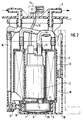
- FIG. 1 shows a first exemplary embodiment of the fuel delivery unit according to the invention in longitudinal section, which is intended to be placed in a fuel tank of a vehicle inserted through an opening in its wall and to be attached with the help of a flange 1 in this opening.
- a substantially cylindrical housing 10 of the fuel delivery module has a cylindrical inner chamber 11 and an inner chamber annular outer chamber 12 on.
- An electric fuel pump Centrifugal pump type 2 is housed in the inner chamber 11.
- An inlet port or intake 3 of the fuel pump 2 extends through an opening at the bottom of the inner chamber 11.
- Die Pump 2 contains in a known manner an electric motor, which is an impeller drives with a rotation speed of approx. 6000 - 24000 U / min.
- the Impeller has 40 - 80 identical, evenly distributed over its circumference Blades and has a diameter of about 35 to 50 mm. The one from the Fuel pump 2 is sucked in and delivered initially following the fuel pump 2, a filter 4 in the outer chamber 12 and then a supply line 5 to a (not shown) Internal combustion engine.
- a flat cylindrical prechamber 6 Under the bottom of the housing 10 is a flat cylindrical prechamber 6 arranged.
- This chamber 6 is formed by an annular side wall 8, on a complementary projection 9 at the bottom of the housing 10 is attached or screwed on, and a bottom wall through a suction filter 7 made of a thin layer of a rigid, permeable Fiber material is formed.
- a suction filter 7 made of a thin layer of a rigid, permeable Fiber material is formed.
- a silencer 13 is arranged in the prechamber so that it covers the entire cross section of the inlet connection 3 and thus prevents that a running noise of the pump 2 transmitted by the fuel straight ways can exit from the inlet port 3.
- the muffler 13 extends across the entire horizontal Cross section of the pre-chamber 6 and lies close to the side wall 8. This arrangement also means that reflected running noise cannot be damped get out of the intake 3.
- the inner structure of the muffler 13 will be discussed later.
- the fuel pump 2 is through a connector 14 and through the Electrical lines 15 passed through flange 1 are supplied with energy.
- Fuel not consumed by the internal combustion engine passes through a Return line 16 to a jet pump 17 which is near the bottom of the tank facing an opening 18 in the wall of a cup 19 is arranged, which surrounds the prechamber 6.
- the jet pump 17 The generated fuel jet tears fuel from the tank through the opening 18 in the cup 19 and thus ensures a compared to the rest of the Tanks raised fuel levels in cup 19.
- Fig. 2 shows a second embodiment of the fuel delivery unit according to the invention. Parts that those of the first embodiment same, have the same reference numerals and will not be described again.
- the silencer 20 in this embodiment comprises a fixed one Housing with an outlet 21, which in the intake 3 of Fuel pump 2 is plugged in tightly. Since in this embodiment efficient damping is ensured even from reflected running noise, without the muffler 20 sealingly connecting to the side wall 8, can have inlet openings for the fuel according to convenience largely arbitrarily on the cylindrical housing of the silencer 20, even on its upper side.
- silencer 20 and prechamber 6 are in cross section dimensioned so that the muffler is free around the axis of its outlet rotated and screwed into the intake 3.
- FIG. 3 shows a perspective view of a further variant of a Muffler in a fuel delivery unit according to the invention is usable.
- the silencer 20 is shown seen obliquely from below, with the outlet nozzle facing away from the viewer 21.
- the inlet opening is on the side of the silencer body facing the viewer arranged and is surrounded by a plurality of projections in a ring shape. Further projections 24 can be on the surface of the muffler be arranged.
- the job of the protrusions is after installation in the Pre-chamber 6 to support the suction filter 7 from the inside and thus to prevent that the suction filter 7 at too high pressure through the flowing through Fuel, for example if the fuel consumption is temporarily increased or if it is more advanced Contamination of the suction filter with the surface of the silencer comes into contact and thereby the effective cross-sectional area of the suction filter 7 is reduced.
- the muffler can be constructed differently inside. He can made entirely of a porous, vibration-damping material, e.g. one open-pored foam material, the fuel has low flow resistance opposed and that emerging from the inlet port 3 Dampens running noise by dissipating the vibrations. This possibility comes in particular with the fuel delivery unit shown in FIG. 1 into consideration.
- FIG. 4 Another possibility is shown in FIG. 4.
- the in this figure in Cross section shown muffler contains a flat in a housing Reflector, here in the form of an air-filled chamber 25, the at his entire outer circumference in a porous, vibration-damping material 26 is embedded.
- the material 26 extends in a ring around the entire outer periphery of chamber 25.
- Through lower inlet opening 22nd entering fuel is deflected laterally at the chamber 25, flows through the porous material 26 and enters through the outlet 21 in the Fuel pump on. From the fuel pump through the outlet port 21 Coming running noise is largely on the reflector 25 in the Pump reflected back. Further damping takes place in material 26.
Landscapes
- Engineering & Computer Science (AREA)
- Mechanical Engineering (AREA)
- General Engineering & Computer Science (AREA)
- Chemical & Material Sciences (AREA)
- Combustion & Propulsion (AREA)
- Chemical Kinetics & Catalysis (AREA)
- Structures Of Non-Positive Displacement Pumps (AREA)
- Pipe Accessories (AREA)
Abstract
Description
- Fig. 1
- ein erstes Ausführungsbeispiel des erfindungsgemäßen Kraftstoff-Förderaggregates;
- Fig. 2
- ein zweites Ausführungsbeispiel des erfindungsgemäßen Kraftstoff-Förderaggregates;
- Fig. 3
- eine perspektivische Ansicht eines Schalldämpfers zur Verwendung in einem erfindungsgemäßen Förderaggregat; und
- Fig. 4
- einen Schalldämpfer im Querschnitt.
Claims (7)
- Kraftstoff-Förderaggregat mit einer als Kreiselpumpe ausgebildeten Kraftstoffpumpe (2), welche wenigstens ein Laufrad mit einer Mehrzahl von Schaufeln aufweist, zum Fördern von Kraftstoff aus einem Vorrat,
dadurch gekennzeichnet, daß
ein kraftstoff-durchströmter Schalldämpfer (13, 20) stromauf von einem Kraftstoff-Einlaßanschluß (3) der Kraftstoffpumpe angeordnet ist. - Kraftstoff-Förderaggregat nach Anspruch 1, dadurch gekennzeichnet, daß der Schalldämpfer (20) ein von dem Kraftstoff durchströmtes Gehäuse mit einem Auslaßstutzen (21) umfaßt, der dicht an dem Einlaßanschluß (3) der Kraftstoffpumpe (2) angeschlossen ist.
- Kraftstoff-Förderaggregat nach Anspruch 1 oder 2, dadurch gekennzeichnet, daß der Schalldämpfer (13, 20) in einer Vorkammer (6) vor dem Einlaßanschluß (3) der Kraftstoffpumpe (2) untergebracht ist, wobei eine Wand der Vorkammer (6) wenigstens zum Teil durch einen Saugfilter (7) gebildet ist, durch zu fördernder Kraftstoff in die Vorkammer (6) eintritt.
- Kraftstoff-Förderaggregat nach Anspruch 3, dadurch gekennzeichnet, daß der Schalldämpfer (13) sich zwischen dem Saugfilter (7) und dem Einlaßanschluß (3) über eine gesamte Querschnittsfläche der Vorkammer (6) erstreckt.
- Kraftstoff-Förderaggregat nach Anspruch 3 oder 4, dadurch gekennzeichnet, daß der Schalldämpfer an einer dem Saugfilter (7) zugewandten Seite Abstandshalter-Vorsprünge (23, 24) trägt.
- Kraftstoff-Förderaggregat nach einem der vorhergehenden Ansprüche, dadurch gekennzeichnet, daß der Schalldämpfer einen Absorptions-Schalldämpferabschnitt (26) umfaßt.
- Kraftstoff-Förderaggregat nach einem der vorhergehenden Ansprüche, dadurch gekennzeichnet, daß der Schalldämpfer einen Reflektor (25) umfaßt.
Applications Claiming Priority (2)
| Application Number | Priority Date | Filing Date | Title |
|---|---|---|---|
| DE19828932A DE19828932A1 (de) | 1998-06-29 | 1998-06-29 | Kraftstoff-Förderaggregat mit einer Kreiselpumpe |
| DE19828932 | 1998-06-29 |
Publications (2)
| Publication Number | Publication Date |
|---|---|
| EP0969201A2 true EP0969201A2 (de) | 2000-01-05 |
| EP0969201A3 EP0969201A3 (de) | 2000-07-05 |
Family
ID=7872363
Family Applications (1)
| Application Number | Title | Priority Date | Filing Date |
|---|---|---|---|
| EP99109845A Withdrawn EP0969201A3 (de) | 1998-06-29 | 1999-05-19 | Kraftstoff-Förderaggregat mit einer Kreiselpumpe und kraftstoffdurchströmtem Schalldämpfer |
Country Status (4)
| Country | Link |
|---|---|
| US (1) | US6308691B1 (de) |
| EP (1) | EP0969201A3 (de) |
| JP (1) | JP2000038970A (de) |
| DE (1) | DE19828932A1 (de) |
Families Citing this family (7)
| Publication number | Priority date | Publication date | Assignee | Title |
|---|---|---|---|---|
| JP2003155963A (ja) * | 2001-11-20 | 2003-05-30 | Kyosan Denki Co Ltd | フューエルポンプモジュールにおける脈動減衰装置 |
| JP2004028054A (ja) | 2002-06-28 | 2004-01-29 | Denso Corp | 燃料供給装置 |
| US20040089274A1 (en) * | 2002-11-12 | 2004-05-13 | Visteon Global Technologies, Inc. | Fuel delivery module integral resonator |
| DE10355309A1 (de) * | 2003-11-27 | 2005-06-30 | Siemens Ag | Kraftstofffördereinheit |
| DE102004034842A1 (de) * | 2004-07-19 | 2006-03-16 | Siemens Ag | Abstützelement mit einer Abstützfläche zur Abstützung einer Kraftstoff-Fördereinheit und Kraftstoff-Fördereinheit |
| JP4785576B2 (ja) * | 2006-03-17 | 2011-10-05 | 株式会社ケーヒン | 自動二輪車用の燃料供給装置 |
| JP5645506B2 (ja) * | 2010-06-29 | 2014-12-24 | 本田技研工業株式会社 | 燃料供給装置 |
Family Cites Families (19)
| Publication number | Priority date | Publication date | Assignee | Title |
|---|---|---|---|---|
| US4844621A (en) * | 1985-08-10 | 1989-07-04 | Nippondenso Co., Ltd. | Fuel pump with passage for attenuating noise generated by impeller |
| US4844704A (en) * | 1986-04-03 | 1989-07-04 | Honda Giken Kogyo Kabushiki Kaisha | Fuel pump assembly |
| US4878518A (en) * | 1986-11-07 | 1989-11-07 | Walbro Corporation | In-tank fuel reservoir with fuel vapor separation |
| JPH0614073Y2 (ja) * | 1989-01-13 | 1994-04-13 | 愛三工業株式会社 | 燃料ポンプ |
| DE3914081A1 (de) * | 1989-04-28 | 1990-11-08 | Bosch Gmbh Robert | Vorrichtung zum foerdern von kraftstoff aus einem vorratstank zur brennkraftmaschine eines kraftfahrzeuges |
| JPH03102089U (de) * | 1990-02-07 | 1991-10-24 | ||
| US4989572A (en) * | 1990-02-16 | 1991-02-05 | General Motors Corporation | Vehicle fuel system with reduced tank heating |
| US5186152A (en) * | 1992-02-10 | 1993-02-16 | General Motors Corporation | Automotive fuel system |
| US5516266A (en) * | 1993-09-07 | 1996-05-14 | Walbro Corporation | Fuel pump tubular pulse damper |
| US5368001A (en) * | 1994-01-21 | 1994-11-29 | Walbro Corporation | Fuel handling system |
| DE4444854C2 (de) | 1994-12-16 | 2002-10-24 | Bosch Gmbh Robert | Förderaggregat |
| JPH08200175A (ja) * | 1995-01-30 | 1996-08-06 | Nippondenso Co Ltd | 燃料ポンプ用フィルタ |
| DE19523634A1 (de) * | 1995-06-29 | 1997-01-02 | Bosch Gmbh Robert | Vorrichtung zur Aufnahme eines Kraftstofförderaggregats innerhalb eines Kraftstoffbehälters |
| US5647328A (en) * | 1995-06-30 | 1997-07-15 | Walbro Corporation | In-tank fuel pump and reservoir |
| US5875816A (en) * | 1996-05-17 | 1999-03-02 | Robert Bosch Gmbh | Fuel feeding module with integrated fuel fine filter |
| US5718208A (en) * | 1996-09-16 | 1998-02-17 | Ford Motor Company | Fuel vapor management system |
| JP3659453B2 (ja) * | 1997-09-23 | 2005-06-15 | 本田技研工業株式会社 | 自動2輪車用燃料供給装置 |
| US5787865A (en) * | 1997-09-29 | 1998-08-04 | General Motors Corporation | Reservoir for motor vehicle fuel tank |
| US5980221A (en) * | 1997-10-27 | 1999-11-09 | Walbro Corporation | Fuel pump pulse damper |
-
1998
- 1998-06-29 DE DE19828932A patent/DE19828932A1/de not_active Withdrawn
-
1999
- 1999-05-19 EP EP99109845A patent/EP0969201A3/de not_active Withdrawn
- 1999-06-25 US US09/344,828 patent/US6308691B1/en not_active Expired - Fee Related
- 1999-06-28 JP JP11182253A patent/JP2000038970A/ja active Pending
Non-Patent Citations (1)
| Title |
|---|
| None |
Also Published As
| Publication number | Publication date |
|---|---|
| DE19828932A1 (de) | 1999-12-30 |
| EP0969201A3 (de) | 2000-07-05 |
| US6308691B1 (en) | 2001-10-30 |
| JP2000038970A (ja) | 2000-02-08 |
Similar Documents
| Publication | Publication Date | Title |
|---|---|---|
| DE19712202C2 (de) | Kraftstoff-Fördersystem | |
| DE69830204T2 (de) | Flüssigkeitspumpen | |
| EP1074743A2 (de) | Elektrische Luftpumpe für ein Kraftfahrzeug | |
| DE69511217T2 (de) | Abflusspumpe | |
| DE10355483A1 (de) | Kraftstoffzuführgerät mit einer Schwingungsdämpfungsstruktur | |
| DE4102161A1 (de) | Luefterrad mit einer topffoermigen nabe | |
| EP0607515B1 (de) | Elektrisch angetriebene Luftpumpe | |
| WO2014075658A2 (de) | Kraftfahrzeug-vakuumpumpe | |
| DE20106595U1 (de) | Gebläseventilator mit einer Zweifach-Einlassanordnung | |
| WO2014075660A2 (de) | Kraftfahrzeug-vakuumpumpe | |
| EP0969201A2 (de) | Kraftstoff-Förderaggregat mit einer Kreiselpumpe und kraftstoffdurchströmtem Schalldämpfer | |
| DE102007040461A1 (de) | Kreiselmotorpumpe | |
| EP1045972B1 (de) | Kraftstoff-fördermodul | |
| EP2510861A2 (de) | Motoranordnung für ein elektromotorisch angetriebenes Haushaltsgerät | |
| DE2147147A1 (de) | Vorrichtung zur Regulierung der Fördermenge von Kreiselpumpen | |
| DE3832648A1 (de) | Staubsauger | |
| DE202004021970U1 (de) | Drehbelüfter für Aquarien und Teiche | |
| DE69922946T2 (de) | Waschmaschine mit unterdrückung des lärms der entleerungspumpe | |
| DE102005006192A1 (de) | Wärmeableitungsstruktur für einen Motor | |
| EP0358731B1 (de) | Axiallüfter | |
| DE3114998C2 (de) | Schalldämmend gekapselte Brennkraftmaschine | |
| DE8030909U1 (de) | Kreiselpumpe zum foerdern von waschfluessigkeit auf die oberflaeche einer scheibe an einem kraftfahrzeug | |
| DE19511911A1 (de) | Ölbadluftfilter | |
| EP0196363A1 (de) | Ein- und mehrstufiger Axialkompressor | |
| EP0122602B1 (de) | Ölnebelgenerator |
Legal Events
| Date | Code | Title | Description |
|---|---|---|---|
| PUAI | Public reference made under article 153(3) epc to a published international application that has entered the european phase |
Free format text: ORIGINAL CODE: 0009012 |
|
| AK | Designated contracting states |
Kind code of ref document: A2 Designated state(s): DE FR IT |
|
| AX | Request for extension of the european patent |
Free format text: AL;LT;LV;MK;RO;SI |
|
| PUAL | Search report despatched |
Free format text: ORIGINAL CODE: 0009013 |
|
| AK | Designated contracting states |
Kind code of ref document: A3 Designated state(s): AT BE CH CY DE DK ES FI FR GB GR IE IT LI LU MC NL PT SE |
|
| AX | Request for extension of the european patent |
Free format text: AL;LT;LV;MK;RO;SI |
|
| 17P | Request for examination filed |
Effective date: 20010105 |
|
| AKX | Designation fees paid |
Free format text: DE FR IT |
|
| STAA | Information on the status of an ep patent application or granted ep patent |
Free format text: STATUS: THE APPLICATION IS DEEMED TO BE WITHDRAWN |
|
| 18D | Application deemed to be withdrawn |
Effective date: 20021203 |