EP0968907A2 - Fahrrad-Anti-Diebstahlvorrichtung mit Energiesparvorrichtung - Google Patents
Fahrrad-Anti-Diebstahlvorrichtung mit Energiesparvorrichtung Download PDFInfo
- Publication number
- EP0968907A2 EP0968907A2 EP98309176A EP98309176A EP0968907A2 EP 0968907 A2 EP0968907 A2 EP 0968907A2 EP 98309176 A EP98309176 A EP 98309176A EP 98309176 A EP98309176 A EP 98309176A EP 0968907 A2 EP0968907 A2 EP 0968907A2
- Authority
- EP
- European Patent Office
- Prior art keywords
- signal
- lock control
- circuit according
- lock
- circuit
- Prior art date
- Legal status (The legal status is an assumption and is not a legal conclusion. Google has not performed a legal analysis and makes no representation as to the accuracy of the status listed.)
- Granted
Links
- 230000004044 response Effects 0.000 claims abstract description 9
- 230000000007 visual effect Effects 0.000 claims 1
- 238000004891 communication Methods 0.000 description 7
- 238000010586 diagram Methods 0.000 description 5
- 238000000034 method Methods 0.000 description 3
- 230000008569 process Effects 0.000 description 3
- 230000003213 activating effect Effects 0.000 description 2
- 239000004973 liquid crystal related substance Substances 0.000 description 2
- 230000003287 optical effect Effects 0.000 description 2
- 230000005540 biological transmission Effects 0.000 description 1
- 230000007246 mechanism Effects 0.000 description 1
- 238000012986 modification Methods 0.000 description 1
- 230000004048 modification Effects 0.000 description 1
Images

Classifications
-
- B—PERFORMING OPERATIONS; TRANSPORTING
- B62—LAND VEHICLES FOR TRAVELLING OTHERWISE THAN ON RAILS
- B62H—CYCLE STANDS; SUPPORTS OR HOLDERS FOR PARKING OR STORING CYCLES; APPLIANCES PREVENTING OR INDICATING UNAUTHORIZED USE OR THEFT OF CYCLES; LOCKS INTEGRAL WITH CYCLES; DEVICES FOR LEARNING TO RIDE CYCLES
- B62H5/00—Appliances preventing or indicating unauthorised use or theft of cycles; Locks integral with cycles
- B62H5/08—Appliances preventing or indicating unauthorised use or theft of cycles; Locks integral with cycles preventing the drive
-
- B—PERFORMING OPERATIONS; TRANSPORTING
- B62—LAND VEHICLES FOR TRAVELLING OTHERWISE THAN ON RAILS
- B62H—CYCLE STANDS; SUPPORTS OR HOLDERS FOR PARKING OR STORING CYCLES; APPLIANCES PREVENTING OR INDICATING UNAUTHORIZED USE OR THEFT OF CYCLES; LOCKS INTEGRAL WITH CYCLES; DEVICES FOR LEARNING TO RIDE CYCLES
- B62H5/00—Appliances preventing or indicating unauthorised use or theft of cycles; Locks integral with cycles
- B62H5/20—Appliances preventing or indicating unauthorised use or theft of cycles; Locks integral with cycles indicating unauthorised use, e.g. acting on signalling devices
Definitions
- the present invention is directed to antitheft devices for bicycles and, more particularly, to an efficient antitheft control device that can be used with a normal lightweight battery.
- Bicycle antitheft devices take many different forms.
- the simplest antitheft device is a lock that physically secures the bicycle to a stationary object such as a fence.
- More elaborate bicycle antitheft devices use electronic circuits to control a lock.
- JP 8-260784 shows an antitheft device that may be operated either manually using a key or electronically using a transmitter.
- Antitheft control devices that operate electronically are often also used in automobiles and are very convenient because the user can operate the antitheft control device by merely pressing a button on a key or key holder to transmit a lock or unlock command signal to the antitheft control device.
- the antitheft control device then locks or unlocks the antitheft device (e.g., the locks on the automobile door) in response to the command signal.
- the command signal receiver in the antitheft control device In order to receive the lock or unlock command signal at any time, the command signal receiver in the antitheft control device must be powered at all times. This does not pose a problem with automobiles because automobiles use rather large batteries that are regularly recharged during operation of the automobile. However, such batteries are not used on bicycles because of the size and weight of the batteries. Electronic devices used with bicycles, such as bicycle computers and automatic transmission devices, must use small batteries that are as lightweight as possible.
- the first aspect of the present invention is directed to an antitheft control circuit for a bicycle in accordance with Claim 1.
- the second aspect of the present invention is directed to a key for operating an antitheft control circuit for a bicycle in accordance with Claim 26.
- Preferred embodiments provide an antitheft control circuit for a bicycle which includes a lock control circuit for providing a lock control signal for at least one of locking and unlocking a bicycle antitheft device, a switch for selectively enabling the lock control circuit to provide the lock control signal, and a sensor for sensing an externally transmitted enabling signal.
- the switch is operatively coupled to the sensor for enabling the lock control circuit, in response to the enabling signal, to provide the lock control signal.
- the switch is disposed between the lock control circuit and a power source such as a small and lightweight battery for providing power to the lock control circuit in response to the enabling signal.
- the lock control circuit also includes a command receiving circuit for receiving a command signal for commanding the lock control circuit to provide the lock control signal. Since power is supplied to the lock control circuit in response to the enabling signal, the antitheft control device may be in an off state until the enabling signal is received. Thereafter, the command receiving circuit may receive the lock command signal, and the antitheft control circuit can process the command and issue the appropriate lock control signal for locking or unlocking the antitheft device.
- the senor is a magnetic sensor and the command receiving circuit is a circuit capable of receiving wireless signals such as infrared signals.
- the key used to operate the antitheft control device includes a magnet for transmitting the enabling signal and a wireless command signal transmitter for transmitting the command signal.
- the magnetic enabling signal is provided to the sensor when the key is placed in close proximity to the sensor.
- the magnetic signal activates the switch which, in turn, powers the lock control circuit.
- the command signal transmitter on the key then may be activated to send the appropriate lock/unlock signal to the lock control circuit for selectively locking and/or unlocking the antitheft control device.
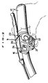
- FIG. 1 is a side view of a bicycle in which a particular embodiment of an antitheft control device according to the present invention may be employed.
- the bicycle includes a frame 1 with a double-loop type of frame unit 2 and a front fork 3; a handle component 4; a drive component 5; a front wheel 6; a rear wheel 7 in which a four-speed internal shifting hub 10 is mounted; front and rear brake devices 8 (only the front brake device is shown); and a shift control element 9 for conveniently operating the internal shifting hub 10.
- Shift control element 9 and internal shifting hub 10 may be constructed in accordance with the teachings of copending European publication No 0,869,054 filed March 25, 1998 entitled "Motor Control Device for a Bicycle" and incorporated herein by reference.
- the drive component 5 has a gear crank 18 that is provided to the lower portion (bottom bracket portion) of the frame body 2, and a chain 19 is wrapped around the gear crank 18 and the internal shifting hub 10.
- a bicycle speed sensor 12 furnished with a bicycle speed sensing lead switch is mounted on the front fork 3.
- This bicycle speed sensor 12 outputs a bicycle speed signal by detecting a magnet 13 mounted on the front wheel 6.
- the handle component 4 has a handle stem 14 that is fixed to the upper portion of the front fork 3 and a handlebar 15 that is fixed to the handle stem 14.
- Brake levers 16 and grips 17 which constitute part of the brake devices 8 are mounted at either end of the handlebar 15.
- Shift control element 9 is mounted on the right-side brake lever 16.
- the shift control element 9 has a control housing 20 formed integrally with the right-side (front-wheel) brake lever 16, two control buttons 21 and 22 disposed next to each other to the left and right on the lower portion of the housing 20, a control dial 23 disposed above the control buttons 21 and 22, and a liquid-crystal display component 24 disposed to the left of the control dial 23.
- the current riding speed is displayed on the liquid-crystal display component 24, as is the speed step selected at the time of the shift.
- the control buttons 21 and 22 are triangular push buttons.
- the control button 21 on the left side is used to perform shifts to a higher speed step, while the control button 22 on the right side is used to perform shifts to a lower speed step.
- the control dial 23 is used to switch among two shifting modes, A and M.
- the shift modes comprise an automatic shift mode (A) and a manual shift mode (M).
- the automatic shift mode is for automatically shifting the internal shifting hub 10 by means of a bicycle speed signal from the bicycle speed sensor 12, and the manual shift mode is for shifting the internal shifting hub 10 through the operation of the control buttons 21 and 22.
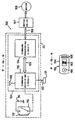
- antitheft control circuit 100 shown in Figure 3 may be used to remotely lock or unlock hub 10.
- antitheft control circuit 100 includes a lock control circuit 104 for providing a lock control signal over a communication path 106 to a motor driver 107 which, in turn, drives a motor 108 for controlling the operational states of hub 10 (including placing hub 10 in the locked and unlocked states); a switch 110 for selectively enabling the lock control circuit 104 to provide the lock control signal; and a sensor 112 for sensing an externally transmitted enabling signal.
- sensor 112 is a magnetic sensor for sensing magnetic signals
- switch 110 is a normally open switch that closes and remains closed only as long as a magnetic signal is sensed by sensor 112.
- switch 110 is a magnetic switch.
- Switch 110 is disposed between a power source such as a battery 116 and lock control circuit 104 for selectively providing power to lock control circuit 104.
- a power source such as a battery 116
- lock control circuit 104 is in the unpowered or off state, and no lock control signals are provided on communication path 106.
- Lock control circuit 104 includes a command receiving circuit 120 for receiving lock/unlock commands and a command processing circuit 124 for processing the commands received by command receiving circuit 120 and providing lock control signals on communication path 106.
- command receiving circuit 120 is constructed for receiving wireless command signals over an antenna 128.
- command receiving circuit 120 could be constructed for receiving radio frequency signals and/or optical signals, such as infrared signals, or some other wireless signals, wherein antenna 128 is replaced by the appropriate optical, infrared or other receiver.
- Command receiving circuit 120 is coupled to an indicator light such as a taillight 121 through a communication path 122 for indicating when a lock/unlock command has been received, and command receiving circuit 120 is coupled to command processing circuit 124 over a communication path 123.
- the command signals received by command receiving circuit 120 may include a lock command signal for locking the antitheft device and/or an unlock command signal for unlocking the antitheft device. Such signals may be separate signals bearing different information, or the lock command signal and the unlock command signal may be identical. In the latter case command processing circuit 124 processes the incoming command based on the current state of the antitheft device. In other words, the incoming command is processed like a lock command signal when the antitheft device is in the unlocked state, and the incoming command is processed like an unlock command signal when the antitheft device is in the locked state. Similarly, the lock control signal provided by command processing circuit 124 may include a lock signal for locking the antitheft device and/or an unlock signal for unlocking the antitheft device.
- Such signals may be separate signals bearing different information, or the lock signal and the unlock signal may be identical.
- the former case may be used when motor driver 107 is an unintelligent controller and merely provides drive signals to motor 108.
- motor driver 107 is an intelligent circuit and processes the incoming lock control signal based on the current state of the antitheft device.
- the lock control signal is processed like a lock signal when the antitheft device is in the unlocked state
- the lock control signal is processed like an unlock signal when the antitheft device is in the locked state.
- FIG 4 is a diagram of a wireless key 150 used to remotely control lock control circuit 104.
- key 150 includes a key base 154, an enabling signal transmitter 158 supported to key base 154 for transmitting the enabling signal for enabling the bicycle antitheft control device, a command signal transmitter 162 supported to key base 154 for transmitting the command signal for locking and/or unlocking the bicycle antitheft device, and an operating button 166 for activating the command transmitter 162.
- the enabling signal transmitter 158 comprises a magnet for emitting a magnetic enabling signal
- command signal transmitter 162 is a wireless signal transmitter for transmitting the wireless commands.
- Command signal transmitter 162 outputs the command signal when operating button 166 is pressed.
- the command signals may include a lock command signal for locking the antitheft device and/or an unlock command signal for unlocking the antitheft device.
- Such signals may be separate signals bearing different information, or the lock command signal and the unlock command signal may be identical.
- the codes generated by the command signal transmitter of one key should be different from the codes transmitted by another key so that an arbitrary key cannot lock or unlock the antitheft device.
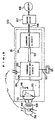
- FIG. 5 is a block diagram showing the operation of antitheft control device 100.
- switch 110 is a normally open switch, so power from battery 116 is not supplied to any of the antitheft control device operating components.
- antitheft control device 100 normally is in a powered off state and battery 116 is not discharged.
- key 150 is placed in close proximity to sensor 112. The magnetic enabling signal causes switch 110 to close, thus providing power from battery 116 to lock control circuit 104.
- button 166 is pressed to cause command transmitter 162 to transmit the lock/unlock command.
- the lock/unlock command is received by command receiving circuit 120 through antenna 128, the receipt of the command is indicated by activating or flashing taillight 121, and the command is communicated to command processing circuit 124 over communication path 123.
- Command processing circuit 124 determines whether to generate the lock and/or unlock signal and provides the appropriate signal to motor driver 107 over communication path 106. Motor driver 107 then drives motor 108 for locking or unlocking hub 10.
- key 150 is removed from the proximity of sensor 112, switch 110 opens, power from battery 116 is cut off from lock control circuit 104, and lock control circuit 104 resumes the powered off state.
- antitheft control device 100 may be a stand-alone system and operate independently of shift control element 9. If desired, the antitheft device may be incorporated into a shift control element 9 that has a manual locking mode such as shown in EP Publication no. 0,869,054 noted above.
Landscapes
- Engineering & Computer Science (AREA)
- Mechanical Engineering (AREA)
- Lock And Its Accessories (AREA)
Applications Claiming Priority (2)
| Application Number | Priority Date | Filing Date | Title |
|---|---|---|---|
| US109450 | 1998-07-02 | ||
| US09/109,450 US5945794A (en) | 1998-07-02 | 1998-07-02 | Power saving antitheft control device for a bicycle |
Publications (3)
| Publication Number | Publication Date |
|---|---|
| EP0968907A2 true EP0968907A2 (de) | 2000-01-05 |
| EP0968907A3 EP0968907A3 (de) | 2000-11-15 |
| EP0968907B1 EP0968907B1 (de) | 2004-06-23 |
Family
ID=22327720
Family Applications (1)
| Application Number | Title | Priority Date | Filing Date |
|---|---|---|---|
| EP98309176A Expired - Lifetime EP0968907B1 (de) | 1998-07-02 | 1998-11-10 | Fahrrad-Anti-Diebstahlvorrichtung mit Energiesparvorrichtung |
Country Status (5)
| Country | Link |
|---|---|
| US (1) | US5945794A (de) |
| EP (1) | EP0968907B1 (de) |
| CN (1) | CN100335734C (de) |
| DE (1) | DE69824707T2 (de) |
| TW (1) | TW495461B (de) |
Families Citing this family (18)
| Publication number | Priority date | Publication date | Assignee | Title |
|---|---|---|---|---|
| KR20010107245A (ko) * | 2000-05-26 | 2001-12-07 | 김용희 | 오토바이 도난 방지 방법 및 이를 수행하기 위한 시스템 |
| JP2002240758A (ja) | 2001-02-19 | 2002-08-28 | Honda Motor Co Ltd | 軽車両における遠隔ロック操作装置 |
| TWI242511B (en) * | 2001-02-19 | 2005-11-01 | Honda Motor Co Ltd | Remote lock operation apparatus for light vehicle |
| EP1504092B2 (de) * | 2002-03-21 | 2014-06-25 | Sangamo BioSciences, Inc. | Verfahren und zusammensetzungen zur verwendung von zinkfinger-endonukleasen zur verbesserung der homologen rekombination |
| TWI232826B (en) * | 2002-09-30 | 2005-05-21 | Honda Motor Co Ltd | Electronic key system for vehicle |
| US20080094192A1 (en) * | 2004-09-01 | 2008-04-24 | Kane Dutt | Lock Apparatus and Method of Use |
| US9027681B2 (en) * | 2009-12-04 | 2015-05-12 | Massachusetts Institute Of Technology | Hybrid sensor-enabled electric wheel and associated systems, multi-hub wheel spoking systems, and methods of manufacturing and installing wheel spokes |
| EP3126184B1 (de) | 2014-04-04 | 2019-09-04 | Superpedestrian, Inc. | Systeme, verfahren und vorrichtungen zum betrieb elektrisch motorisierter fahrzeuge |
| US10308065B2 (en) | 2014-04-04 | 2019-06-04 | Superpedestrian, Inc. | Devices and methods for connecting a spoke to a hub |
| GB201512700D0 (en) * | 2014-08-01 | 2015-08-26 | Ford Global Tech Llc | Electric bicycle |
| CN111216558A (zh) | 2014-11-24 | 2020-06-02 | 极步公司 | 机动车轮的设备和方法 |
| CN104890768B (zh) * | 2015-05-25 | 2017-11-28 | 江苏金彭车业有限公司 | 电动车防盗告警系统及其告警方法 |
| CN107489317B (zh) * | 2016-06-13 | 2021-04-09 | 江苏宏溥科技有限公司 | 节能车锁及管理方法 |
| CN106347528A (zh) * | 2016-10-13 | 2017-01-25 | 天津恺丰义科技有限公司 | 一种电动自行车防盗监控系统 |
| US10444370B2 (en) * | 2017-04-29 | 2019-10-15 | HangZhou HaiCun Information Technology Co., Ltd. | Shared bicycle comprising an infrared sensor |
| US10562580B2 (en) * | 2017-04-29 | 2020-02-18 | HangZhou HaiCun Information Technology Co., Ltd. | Shared infrared (IR) bicycle and methods |
| DE102018111286A1 (de) * | 2018-05-11 | 2019-11-14 | ABUS August Bremicker Söhne KG | Handsender für ein mobiles Schloss |
| FR3164180A1 (fr) * | 2024-07-02 | 2026-01-09 | Vel'co | Système et procédé de contrôle d’une assistance électrique au pédalage d’un véhicule à pédales |
Citations (2)
| Publication number | Priority date | Publication date | Assignee | Title |
|---|---|---|---|---|
| JPH08260784A (ja) | 1995-03-24 | 1996-10-08 | Sekisui Chem Co Ltd | 自転車用遠隔操作錠 |
| EP0869054A1 (de) | 1997-03-31 | 1998-10-07 | Shimano Inc. | Motorsteuerung für ein Fahrrad |
Family Cites Families (10)
| Publication number | Priority date | Publication date | Assignee | Title |
|---|---|---|---|---|
| DE9106147U1 (de) * | 1991-05-17 | 1991-08-08 | Lii, Jein-Hei, Tainan | Drahtlose Diebstahlsicherung für Motorräder |
| US5408213A (en) * | 1993-05-12 | 1995-04-18 | Ungarsohn; Benjamin I. | Portable breakaway alarm system |
| DE4434571A1 (de) * | 1993-10-01 | 1995-04-06 | Marquardt Gmbh | Elektronisches Türschließsystem an einem Kraftfahrzeug |
| US5637984A (en) * | 1994-10-20 | 1997-06-10 | Nanotechnology, Inc. | Pseudo-mechanical system incorporating ohmic electromechanical transducer and electrical generator |
| US5534847A (en) * | 1994-11-23 | 1996-07-09 | Mcgregor; Gerald C. | Bicycle alarm system |
| US5783996A (en) * | 1996-07-15 | 1998-07-21 | Muszynski; Francis E. | Portable gravity activated alarm device for golf bags and other similar items |
| DE29619966U1 (de) * | 1996-11-16 | 1997-04-30 | Gann, Simon, 75397 Simmozheim | Wegfahrsperre/Alarmanlage für Zweiräder |
| FR2757474B1 (fr) * | 1996-12-20 | 1999-04-23 | Allouche Joelle Nicole Chantal | Dispositif antivol de haute securite pour engins motorises |
| GB9626743D0 (en) * | 1996-12-23 | 1997-02-12 | Anwyl Davies Nicholas | A lock |
| DE19741643A1 (de) * | 1997-09-22 | 1999-03-25 | Klaus Dr Keck | Vorrichtung zur Sicherung von Fahrrädern, Motorrädern und dergleichen |
-
1998
- 1998-07-02 US US09/109,450 patent/US5945794A/en not_active Expired - Lifetime
- 1998-10-29 CN CNB981234909A patent/CN100335734C/zh not_active Expired - Fee Related
- 1998-11-10 EP EP98309176A patent/EP0968907B1/de not_active Expired - Lifetime
- 1998-11-10 DE DE69824707T patent/DE69824707T2/de not_active Expired - Lifetime
- 1998-11-18 TW TW087119115A patent/TW495461B/zh not_active IP Right Cessation
Patent Citations (2)
| Publication number | Priority date | Publication date | Assignee | Title |
|---|---|---|---|---|
| JPH08260784A (ja) | 1995-03-24 | 1996-10-08 | Sekisui Chem Co Ltd | 自転車用遠隔操作錠 |
| EP0869054A1 (de) | 1997-03-31 | 1998-10-07 | Shimano Inc. | Motorsteuerung für ein Fahrrad |
Also Published As
| Publication number | Publication date |
|---|---|
| CN100335734C (zh) | 2007-09-05 |
| DE69824707D1 (de) | 2004-07-29 |
| CN1240866A (zh) | 2000-01-12 |
| US5945794A (en) | 1999-08-31 |
| TW495461B (en) | 2002-07-21 |
| EP0968907A3 (de) | 2000-11-15 |
| EP0968907B1 (de) | 2004-06-23 |
| DE69824707T2 (de) | 2005-08-04 |
Similar Documents
| Publication | Publication Date | Title |
|---|---|---|
| EP0968907B1 (de) | Fahrrad-Anti-Diebstahlvorrichtung mit Energiesparvorrichtung | |
| EP1057720B1 (de) | Magnetisch betätigte Anti-Diebstahlvorrichtung für Fahrräder | |
| TWI853975B (zh) | 電動腳踏車 | |
| EP1262925B1 (de) | Fernverriegelungsvorrichtung für Fahrzeuge | |
| EP1886884B1 (de) | Fahrzeugsteuerungsvorrichtung und damit ausgestattetes Fahrzeug | |
| US7062980B2 (en) | Bicycle shift control device with decreased stress during shifting | |
| KR100606483B1 (ko) | 차량용 잠금장치 | |
| JP4100568B2 (ja) | 車両用リモートキー | |
| US7190255B2 (en) | Anti-theft device in motorcycle | |
| EP1120337B1 (de) | Verfahren und Einrichtung zum Auswählen des Verarbeitungsmodus für einen Fahrradcomputer | |
| EP1544067B1 (de) | Elektronisches fahrzeugschlüsselsystem | |
| CA2441735A1 (en) | Anti-theft device in motorcycle | |
| US20100077804A1 (en) | Vehicle trunk locking device | |
| EP0860353A1 (de) | Indentifizierungsvorrichtung für Zweiradfahrzeug | |
| JP2000095181A (ja) | 自転車用変速システム | |
| JP3305681B2 (ja) | 自転車用盗難防止制御装置、キー及び盗難防止システム | |
| JP2000190885A (ja) | 自転車用錠 | |
| JP3503108B2 (ja) | 自転車用リモコン式オート錠前の安全装置 | |
| WO2012046477A1 (ja) | 車両用キーおよびアンサーバック装置 | |
| JP6147046B2 (ja) | リモコンシステム | |
| JP4519976B2 (ja) | 盗難防止装置 | |
| JPH09226649A (ja) | 二輪車 | |
| US20240251460A1 (en) | Bicycle component | |
| JPH0715461U (ja) | オートチェンジ | |
| JPH0543557B2 (de) |
Legal Events
| Date | Code | Title | Description |
|---|---|---|---|
| PUAI | Public reference made under article 153(3) epc to a published international application that has entered the european phase |
Free format text: ORIGINAL CODE: 0009012 |
|
| 17P | Request for examination filed |
Effective date: 19981126 |
|
| AK | Designated contracting states |
Kind code of ref document: A2 Designated state(s): DE FR GB IT |
|
| AX | Request for extension of the european patent |
Free format text: AL;LT;LV;MK;RO;SI |
|
| PUAL | Search report despatched |
Free format text: ORIGINAL CODE: 0009013 |
|
| AK | Designated contracting states |
Kind code of ref document: A3 Designated state(s): AT BE CH CY DE DK ES FI FR GB GR IE IT LI LU MC NL PT SE |
|
| AX | Request for extension of the european patent |
Free format text: AL;LT;LV;MK;RO;SI |
|
| AKX | Designation fees paid |
Free format text: DE FR GB IT |
|
| 17Q | First examination report despatched |
Effective date: 20021212 |
|
| GRAP | Despatch of communication of intention to grant a patent |
Free format text: ORIGINAL CODE: EPIDOSNIGR1 |
|
| GRAS | Grant fee paid |
Free format text: ORIGINAL CODE: EPIDOSNIGR3 |
|
| GRAA | (expected) grant |
Free format text: ORIGINAL CODE: 0009210 |
|
| AK | Designated contracting states |
Kind code of ref document: B1 Designated state(s): DE FR GB IT |
|
| REG | Reference to a national code |
Ref country code: GB Ref legal event code: FG4D |
|
| REF | Corresponds to: |
Ref document number: 69824707 Country of ref document: DE Date of ref document: 20040729 Kind code of ref document: P |
|
| ET | Fr: translation filed | ||
| PLBE | No opposition filed within time limit |
Free format text: ORIGINAL CODE: 0009261 |
|
| STAA | Information on the status of an ep patent application or granted ep patent |
Free format text: STATUS: NO OPPOSITION FILED WITHIN TIME LIMIT |
|
| 26N | No opposition filed |
Effective date: 20050324 |
|
| PGFP | Annual fee paid to national office [announced via postgrant information from national office to epo] |
Ref country code: GB Payment date: 20051109 Year of fee payment: 8 |
|
| GBPC | Gb: european patent ceased through non-payment of renewal fee |
Effective date: 20061110 |
|
| PG25 | Lapsed in a contracting state [announced via postgrant information from national office to epo] |
Ref country code: GB Free format text: LAPSE BECAUSE OF NON-PAYMENT OF DUE FEES Effective date: 20061110 |
|
| PGFP | Annual fee paid to national office [announced via postgrant information from national office to epo] |
Ref country code: FR Payment date: 20131108 Year of fee payment: 16 |
|
| PGFP | Annual fee paid to national office [announced via postgrant information from national office to epo] |
Ref country code: IT Payment date: 20141111 Year of fee payment: 17 |
|
| REG | Reference to a national code |
Ref country code: FR Ref legal event code: ST Effective date: 20150731 |
|
| PG25 | Lapsed in a contracting state [announced via postgrant information from national office to epo] |
Ref country code: FR Free format text: LAPSE BECAUSE OF NON-PAYMENT OF DUE FEES Effective date: 20141201 |
|
| PGFP | Annual fee paid to national office [announced via postgrant information from national office to epo] |
Ref country code: DE Payment date: 20151103 Year of fee payment: 18 |
|
| PG25 | Lapsed in a contracting state [announced via postgrant information from national office to epo] |
Ref country code: IT Free format text: LAPSE BECAUSE OF NON-PAYMENT OF DUE FEES Effective date: 20151110 |
|
| REG | Reference to a national code |
Ref country code: DE Ref legal event code: R119 Ref document number: 69824707 Country of ref document: DE |
|
| PG25 | Lapsed in a contracting state [announced via postgrant information from national office to epo] |
Ref country code: DE Free format text: LAPSE BECAUSE OF NON-PAYMENT OF DUE FEES Effective date: 20170601 |