EP0968339B1 - Befestigung von flächenelementen in nuten von klemmprofilstäben - Google Patents
Befestigung von flächenelementen in nuten von klemmprofilstäben Download PDFInfo
- Publication number
- EP0968339B1 EP0968339B1 EP98922617A EP98922617A EP0968339B1 EP 0968339 B1 EP0968339 B1 EP 0968339B1 EP 98922617 A EP98922617 A EP 98922617A EP 98922617 A EP98922617 A EP 98922617A EP 0968339 B1 EP0968339 B1 EP 0968339B1
- Authority
- EP
- European Patent Office
- Prior art keywords
- metal strip
- sheet metal
- groove
- wall
- surface elements
- Prior art date
- Legal status (The legal status is an assumption and is not a legal conclusion. Google has not performed a legal analysis and makes no representation as to the accuracy of the status listed.)
- Expired - Lifetime
Links
Images

Classifications
-
- F—MECHANICAL ENGINEERING; LIGHTING; HEATING; WEAPONS; BLASTING
- F16—ENGINEERING ELEMENTS AND UNITS; GENERAL MEASURES FOR PRODUCING AND MAINTAINING EFFECTIVE FUNCTIONING OF MACHINES OR INSTALLATIONS; THERMAL INSULATION IN GENERAL
- F16B—DEVICES FOR FASTENING OR SECURING CONSTRUCTIONAL ELEMENTS OR MACHINE PARTS TOGETHER, e.g. NAILS, BOLTS, CIRCLIPS, CLAMPS, CLIPS OR WEDGES; JOINTS OR JOINTING
- F16B7/00—Connections of rods or tubes, e.g. of non-circular section, mutually, including resilient connections
- F16B7/04—Clamping or clipping connections
- F16B7/044—Clamping or clipping connections for rods or tubes being in angled relationship
- F16B7/0446—Clamping or clipping connections for rods or tubes being in angled relationship for tubes using the innerside thereof
-
- E—FIXED CONSTRUCTIONS
- E04—BUILDING
- E04B—GENERAL BUILDING CONSTRUCTIONS; WALLS, e.g. PARTITIONS; ROOFS; FLOORS; CEILINGS; INSULATION OR OTHER PROTECTION OF BUILDINGS
- E04B2/00—Walls, e.g. partitions, for buildings; Wall construction with regard to insulation; Connections specially adapted to walls
- E04B2/74—Removable non-load-bearing partitions; Partitions with a free upper edge
- E04B2/7407—Removable non-load-bearing partitions; Partitions with a free upper edge assembled using frames with infill panels or coverings only; made-up of panels and a support structure incorporating posts
- E04B2/7453—Removable non-load-bearing partitions; Partitions with a free upper edge assembled using frames with infill panels or coverings only; made-up of panels and a support structure incorporating posts with panels and support posts, extending from floor to ceiling
-
- F—MECHANICAL ENGINEERING; LIGHTING; HEATING; WEAPONS; BLASTING
- F16—ENGINEERING ELEMENTS AND UNITS; GENERAL MEASURES FOR PRODUCING AND MAINTAINING EFFECTIVE FUNCTIONING OF MACHINES OR INSTALLATIONS; THERMAL INSULATION IN GENERAL
- F16B—DEVICES FOR FASTENING OR SECURING CONSTRUCTIONAL ELEMENTS OR MACHINE PARTS TOGETHER, e.g. NAILS, BOLTS, CIRCLIPS, CLAMPS, CLIPS OR WEDGES; JOINTS OR JOINTING
- F16B21/00—Means for preventing relative axial movement of a pin, spigot, shaft or the like and a member surrounding it; Stud-and-socket releasable fastenings
- F16B21/10—Means for preventing relative axial movement of a pin, spigot, shaft or the like and a member surrounding it; Stud-and-socket releasable fastenings by separate parts
- F16B21/20—Means for preventing relative axial movement of a pin, spigot, shaft or the like and a member surrounding it; Stud-and-socket releasable fastenings by separate parts for bolts or shafts without holes, grooves, or notches for locking members
Definitions
- the invention relates to a fastening of surface elements in grooves of clamping profile bars according to Features of the preamble of claim 1.
- Such fasteners are used when surface elements and clamping profile bars assembled to form wall elements with which, for example, mobile room layouts can be achieved should be.
- the wall elements then serve as presentation walls or are used as supporting walls in production plants or the like. used.
- the surface elements also serve to stiffen the entire Wall.
- the fasteners help to relieve the impact connection means Angled clamping profile bars at.
- DE 9 110 357 U is a fastening with the input known features known.
- the well-known spring plate is multi-legged. His thighs rest on the bottom of the Groove, on a groove wall and on the inserted surface element from. In addition, the well-known spring plate on two legs slotted several times. The formation of the known spring plate assumes that several punching and Deformation processes take place. This manufacture of the known Spring plate is comparatively complex and leads to a voluminous element with a corresponding storage volume.
- the spring plate is able used in conjunction with thinner and thicker surface elements to become.
- the angle of attack of the spring leg pressing on the surface element the smaller, the thicker the surface element is.
- the thicker surface elements Clawing the edge of the spring plate leg on the surface element, the thicker the latter.
- the clamping profile bar is essentially U-shaped so that its Groove extends between the two legs, between which the Surface element is arranged.
- the surface element must be something be wider than the distance between the legs so that it surface element not inserted into the clamping profile rod doesn't fall out.
- the invention is based on the object a fastening with the features mentioned above improve that even thicker surface elements in the grooves of Clamp profile bars held securely and with simplified means are.
- the undeflected Spring plate is the simplest training. It is a plate-like and unslit sheet metal strip, that is is fully available and practically flat. He can by simply cut to length from a metal strip roll become. Undeflected, the metal strip is completely flat, maybe apart from minor deformations that are due to the winding of the metal strip on a roll after a longer storage period.
- the attachment is designed so that the Groove off-center to the clamping profile rod near a first one Outside wall is arranged, and that the groove and the hollow chamber together form a deflection space of the sheet metal strip. Consequently can the sheet metal strip over a considerable Elevation section deformed, which is different for the recording thick surface elements is important.
- the sheet metal strip near the groove opening is arranged to the groove, inserting a surface element regardless of its thickness in any case considerable deformation of the sheet metal strip and thus to corresponding Holding forces. It is also achieved that the groove is covered by the metal strip. Complete coverage of the Groove arises when the sheet metal strip extends over the extends the entire length of the clamping profile bar. Besides, is the extent of coverage of the groove from the width of the sheet metal strip dependent across the profile bar.
- the attachment is expediently designed such that that the metal strip is longer than high. With such a Formation of the metal strip results in the usual Dimensioning the cross sections of the clamping profile bars a safe Bracket for the metal strip.
- the investment or pressing surface of the sheet metal strip on the surface element comparatively large. A surface element is therefore only at in certain areas.
- a particularly uniform mounting of a surface element on one edge results when the sheet metal strip extends practically over the entire length of the clamping profile bar.
- the sheet metal strip acts on an edge of a surface element then over its entire edge length.
- An advantageous arrangement of the sheet metal strip inside of the clamping profile rod is achieved in that the sheet metal strip with one extending over the entire length of the strip Edge within a hollow chamber of the clamping profile bar is arranged.
- the Hollow chamber are formed so that the sheet metal strip on an abutment against its edge inserted into the hollow chamber Bends are found by an inserted surface element caused.
- a further embodiment of the attachment is thereby characterized that the hollow chamber a third, with the second one-piece outer wall that forms the groove mouth having.
- the cavity is as wide as possible from the center of the clamping profile bar, in particular if the third outer wall corresponds to the second outer wall has minimal wall thickness.
- the attachment can be improved in that the sheet metal strip at a distance against its bending direction to its edge opposite the surface element is supported on the clamping profile rod. Because of this, on the one hand possible to optimally design the clamping bar profile, for example in the desired way thin-walled, but on the other hand one use comparatively wide metal strips and to measure the deflection space in a suitable manner.
- the attachment can be done in this way be formed that the third outer wall on its inner surface on the nut side and / or the second outer wall side Has sheet metal strip supporting projection.
- the lead the third outer wall serves, for example, with the aforementioned Support of the sheet metal strip against its direction of bending to achieve a predetermined support length.
- the attachment is so trained that the sheet metal strip lengthways in the clamping bar profile is inserted.
- the rod 12 extends vertically to the display level over a predetermined length.
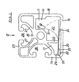
- the profile rod 12 is substantially square. Accordingly there are outer walls 18 to 20 and 25 of the same length. These outer walls are with a central rod 26 and further trained according to the profiling requirements Crosspieces 27 in one piece connection.
- the Outer walls 19, 25 are each with undercut grooves 28 provided and the outer wall 20 has the groove mouth 15 one Groove 11, in which a surface element 10 with its longitudinal edge can be inserted.
- This longitudinal groove 11 extends parallel to the outer wall 18, which is smooth over its entire width passes through to beyond the center of the profile near the groove 28 associated with outer wall 25.
- the metal strip is essentially arranged parallel to the outer wall 20 and extends inside a hollow chamber 17 of the clamping profile rod 12 from the latter Outer wall 19 up to the vicinity of the outer wall 18 the sheet metal strip 13 in its removable from FIGS. 1 to 3 Height adapted to the distance of the outer walls 18, 19 and takes practically the entire width between these walls.
- Fig.1 shows that the metal strip 13, the groove 11 in the Near the groove mouth 15 covers almost completely.
- the sheet metal strip 13 with its edge 13 ' abuts the outer wall 19.
- the sheet metal strip 13 is a spring plate and is, for example made of resilient steel.
- the length of the metal strip 13, i.e. its extension perpendicular to the plane of the representation, is chosen according to the fastening requirements.
- the length of the sheet metal strip 13 is expediently greater, as the height evident from FIGS. 1 to 3.
- the metal strip 13 can also extend over the entire length of the clamping profile bar 12 extend.
- the assembly of the metal strip 13 and the clamping rod 12 is conveniently such that the sheet metal strip 13 preferably in the longitudinal direction in the Clamping rod profile 10 is inserted.
- Fig. 1 shows two extreme positions 29.30 of a flat sheet metal strip 13, that is is accordingly plate-like.
- the sheet metal strip 13 is not slotted and thus unwound as a strip material from a roll and cut to length can be manufactured.
- the one through the extreme positions 29.30 illustrated scope allows the longitudinal insertion of the metal strip 13 in the clamping profile bar 12 also when the sheet metal strip 13 should not be ideally flat.
- the groove 11 and the sheet metal strip 13 essentially receiving hollow chamber 17 form a coherent Space in which there is also the deflection space 21 of the sheet metal strip 13 is located. 1 characterizes this deflection space 21 an extreme position 31 of the sheet metal strip 13 and a line 32, on which the surface-side edge 13 '' depending on the thickness of the inserted surface elements 10 come to rest can. This deflection space 21 is also supported by the Clamp profile bar 12 determined.
- the projection 23 secures with its fixed distance to Projection 33 a defined deflection of the metal strip 13 even if its edge 13 'from the outer wall 19 something is removed.
- the deflection of the Sheet metal strip 13 depends on the thickness of the surface elements 10 is. If the surface element 10 is comparatively thin, is its thickness is only about 25% of the width of the groove 15, so is the sheet metal strip, the edge 13 '' in the case of a still non-deformation of the support surface 14 immediately is only slightly deflected. It takes place a very strong claw of this edge 13 '' on the nut side Surface 10 'of the surface element 10. If the thickness of the Surface element 10 is larger and practically the entire width corresponds to the groove 15, the edge 13 '' of the metal strip 13 moved considerably further to the central rod 26. The claw of the edge 13 '' with the surface 10 'is then somewhat lower, but the contact pressure of the sheet metal strip is 13 larger, so that sufficient in this case Determination of the element 10 takes place.
Landscapes
- Engineering & Computer Science (AREA)
- General Engineering & Computer Science (AREA)
- Architecture (AREA)
- Mechanical Engineering (AREA)
- Physics & Mathematics (AREA)
- Electromagnetism (AREA)
- Civil Engineering (AREA)
- Structural Engineering (AREA)
- Clamps And Clips (AREA)
Description
- Fig.1
- einen Querschnitt eines Klemmprofilstabs mit eingelegtem Blechstreifen, und
- Fig.2,3
- einen der Fig.1 entsprechenden Querschnitt, jedoch mit unterschiedlich breiten eingesteckten Flächenelementen, die den Blechstreifen entsprechend ihrer Dicke auslenken.
Claims (8)
- Befestigung von Flächenelementen (10) in Nuten (11) von Klemmprofilstäben (12), mit einem in einer Nut (11) angeordneten Federblech, das von einem in die Nut (11) eingesteckten Flächenelement (10) ausgelenkt ist und dieses dementsprechend gegen eine in der Nut (11) befindliche Abstützfläche (14) drückt, wobei das Federblech ein unausgelenkt plattenartiger und ungeschlitzter Blechstreifen (13) ist, dadurch gekennzeichnet, daß die Nut (11) und eine den Blechstreifen (13) aufnehmenden Hohlkammer (17) des Klemmprofilstabs (12) gemeinsam einen einer Auslenkung des Blechstreifens (13) dienenden Auslenkraum (21) bilden, bei dem die Nut (11) außenmittig zum Klemmprofilstab (12) in der Nähe einer ersten Außenwand (18) angeordnet ist, und bei dem sich die Hohlkammer (17) von der Nut (11) bis zu einer zweiten, der ersten parallelen Außenwand (19) erstreckt und den Blechstreifen (13) in der Nähe einer Nutenmündung (15) quer zur Nut (11) angeordnet hält.
- Befestigung von Flächenelementen (10) nach Anspruch 1, dadurch gekennzeichnet, daß der Blechstreifen (13) länger als hoch ist.
- Befestigung von Flächenelementen (10) nach Anspruch 1 oder 2, dadurch gekennzeichnet, daß sich der Blechstreifen (13) praktisch über die gesamte Länge des Klemmprofilstabs (12) erstreckt.
- Befestigung von Flächenelementen (3) nach einem der Ansprüche 1 bis 4, dadurch gekennzeichnet, daß der Blechstreifen (13) mit einem sich über die gesamte Streifenlänge erstreckenden Rand (16) innerhalb der Hohlkammer (17) des Klemmprofilstabs (12) angeordnet ist.
- Befestigung von Flächenelementen (10) nach einem der Ansprüche 1 bis 4, dadurch gekennzeichnet, daß die Hohlkammer (17) eine dritte, mit der zweiten einstückige Außenwand (20) bildet, die die Nutenmündung (11) aufweist.
- Befestigung von Flächenelementen (10) nach einem der Ansprüche 1 bis 5, dadurch gekennzeichnet, daß der Blechstreifen (13) entgegen seiner Ausbiegerichtung mit Abstand zu seiner dem Flächenelement (10) gegenüberliegenden Kante (13') am Klemmprofilstab (10) abgestützt ist.
- Befestigung von Flächenelementen (10) nach einem der Ansprüche 5 oder 6, dadurch gekennzeichnet, daß die dritte Außenwand (20) an ihrer Innenfläche (22) nutseitig und/oder zweiteaußenwandseitig einen den Blechstreifen (13) abstützenden Vorsprung (23,24) aufweist.
- Befestigung von Flächenelementen (10) nach einem der Ansprüche 1 bis 7, dadurch gekennzeichnet, daß der Blechstreifen (13) längs in das Klemmstabprofil (10) eingeschoben ist.
Applications Claiming Priority (3)
| Application Number | Priority Date | Filing Date | Title |
|---|---|---|---|
| DE29704548U | 1997-03-13 | ||
| DE29704548U DE29704548U1 (de) | 1997-03-13 | 1997-03-13 | Befestigung von Flächenelementen in Nuten von Klemmprofilstäben |
| PCT/EP1998/001415 WO1998040575A1 (de) | 1997-03-13 | 1998-03-12 | Befestigung von flächenelementen in nuten von klemmprofilstäben |
Publications (2)
| Publication Number | Publication Date |
|---|---|
| EP0968339A1 EP0968339A1 (de) | 2000-01-05 |
| EP0968339B1 true EP0968339B1 (de) | 2002-10-30 |
Family
ID=8037400
Family Applications (1)
| Application Number | Title | Priority Date | Filing Date |
|---|---|---|---|
| EP98922617A Expired - Lifetime EP0968339B1 (de) | 1997-03-13 | 1998-03-12 | Befestigung von flächenelementen in nuten von klemmprofilstäben |
Country Status (4)
| Country | Link |
|---|---|
| EP (1) | EP0968339B1 (de) |
| AT (1) | ATE226993T1 (de) |
| DE (2) | DE29704548U1 (de) |
| WO (1) | WO1998040575A1 (de) |
Families Citing this family (3)
| Publication number | Priority date | Publication date | Assignee | Title |
|---|---|---|---|---|
| DE20001923U1 (de) | 2000-02-04 | 2000-05-18 | Dämmler Türensysteme GmbH, 08058 Zwickau | Rahmenprofilschiene zur Stabilisierung von frei im Raum anordenbaren Wandelementen |
| DE20300413U1 (de) | 2003-01-10 | 2003-03-27 | Portal Vordach-Systeme GmbH, 33142 Büren | Vorrichtung zum Verbinden von Platten |
| WO2008094566A2 (en) * | 2007-02-01 | 2008-08-07 | Marlite, Inc. | Wall panel system |
Family Cites Families (11)
| Publication number | Priority date | Publication date | Assignee | Title |
|---|---|---|---|---|
| US2464470A (en) * | 1945-09-24 | 1949-03-15 | Grand Rapids Store Equip Co | Store furniture |
| DE1061991B (de) * | 1954-12-23 | 1959-07-23 | Williams & Williams Ltd | Vorrichtung zum Befestigen einer Platte, Scheibe od. dgl., insbesondere aus Glas an einem Traeger |
| US3261625A (en) * | 1961-12-27 | 1966-07-19 | Reynolds Metals Co | Joint between vertical and horizontal members in a partition construction |
| FR2376927A1 (fr) * | 1977-01-06 | 1978-08-04 | Diffusion Materiel Stockage | Dispositif d'assemblage d'elements de cloison amovible |
| DE7925197U1 (de) * | 1978-09-11 | 1979-12-06 | Regie Nationale Des Usines Renault, Boulogne-Billancourt, Hauts-De-Seine (Frankreich) | Halteklammer |
| FR2456246B1 (fr) * | 1979-05-08 | 1985-11-08 | Bobath Peter | Dispositif pour joindre bord a bord des panneaux |
| DE3605949A1 (de) * | 1986-02-25 | 1987-08-27 | Dieter Kellermann | Zugfeste einspannung eines flaechenelementes in eine von zwei im abstand voneinander parallel zueinander verlaufenden widerlagerflaechen gebildete lagerstelle |
| EP0262282A1 (de) * | 1986-10-02 | 1988-04-06 | PICO-GLASS S.p.A. | Halteklammer, mit der zwei Platten zu einem Bilderhalter zusammengeklemmt werden können und an der ein Rahmen angebracht werden kann |
| DE9014987U1 (de) * | 1990-10-31 | 1991-01-10 | Häfele KG, 7270 Nagold | Beschlag |
| US5251418A (en) * | 1991-07-17 | 1993-10-12 | The Stanley Works | Panel door frame assembly |
| DE9110357U1 (de) * | 1991-08-22 | 1991-11-28 | Pies, Gerrit, 5650 Solingen | Befestigung für die Kanten von Flächenelementen in Nuten von Klemmprofilstäben |
-
1997
- 1997-03-13 DE DE29704548U patent/DE29704548U1/de not_active Expired - Lifetime
-
1998
- 1998-03-12 EP EP98922617A patent/EP0968339B1/de not_active Expired - Lifetime
- 1998-03-12 DE DE59806118T patent/DE59806118D1/de not_active Expired - Lifetime
- 1998-03-12 WO PCT/EP1998/001415 patent/WO1998040575A1/de not_active Ceased
- 1998-03-12 AT AT98922617T patent/ATE226993T1/de active
Also Published As
| Publication number | Publication date |
|---|---|
| WO1998040575A1 (de) | 1998-09-17 |
| DE59806118D1 (de) | 2002-12-05 |
| DE29704548U1 (de) | 1998-07-16 |
| EP0968339A1 (de) | 2000-01-05 |
| ATE226993T1 (de) | 2002-11-15 |
Similar Documents
| Publication | Publication Date | Title |
|---|---|---|
| DE2502807C2 (de) | Leitungsklemme | |
| EP2059146B1 (de) | Schubkasten | |
| DE2435147C3 (de) | Aus teilweise abgebogenen Profilstangen gebildetes Gestell | |
| DE2412774A1 (de) | Im schlitz einer platte verschiebbar zu lagernde mutter | |
| EP4069933B1 (de) | Beschattungsvorrichtung | |
| DE3042309C2 (de) | Elastische Halteklammer für Rundstäbe mit variablen Durchmessern | |
| EP0968339B1 (de) | Befestigung von flächenelementen in nuten von klemmprofilstäben | |
| DE2923903C2 (de) | ||
| CH681883A5 (de) | ||
| DE3405094A1 (de) | Elastische halteklammer fuer rundstaebe mit variablen durchmessern | |
| DE29709362U1 (de) | Schublade | |
| DE10029544A1 (de) | Befestigungselement | |
| EP3727091B1 (de) | Anordnung aus wenigstens einer relingstange und wenigstens einem wandelement einer schublade | |
| DE2150650B2 (de) | Abstandhalter zur Aufnahme der Längsstäbe von Bewehrungsmatten | |
| DE102022112947A1 (de) | Anordnung aus einem Regalboden und einem Trennelement, sowie Trennelement | |
| DE4404390C2 (de) | Haltevorrichtung für Wandschalungen | |
| DE3802971C2 (de) | Elektrisches Installationsgerät, wie Schalter, Taster, Tastschalter od. dgl. | |
| DE2741875A1 (de) | Verbesserungen an buerstenhaltern mit feder, die aus sich selbst aufrollendem, elastischem band besteht | |
| EP0358854B1 (de) | Rahmen für Bandfördervorrichtung | |
| DE3625138C1 (en) | Furniture, in particular office furniture | |
| DE29805841U1 (de) | Anschlußplatte für einen Montagerahmen zur Installation eines Sanitärapparates | |
| DE9314672U1 (de) | Tragelement zum hängenden Halten einer Halteschiene an einer Gebäudedecke | |
| DE2166276C3 (de) | Verstellbeschlag zur einstellbaren Befestigung der Frontplatte eines ausziehbaren Möbelteiles | |
| EP4296444A2 (de) | Montagevorrichtung | |
| DE2016298C (de) | Drucktastenschalter mit beweglichem Schieber |
Legal Events
| Date | Code | Title | Description |
|---|---|---|---|
| PUAI | Public reference made under article 153(3) epc to a published international application that has entered the european phase |
Free format text: ORIGINAL CODE: 0009012 |
|
| 17P | Request for examination filed |
Effective date: 19990702 |
|
| AK | Designated contracting states |
Kind code of ref document: A1 Designated state(s): AT CH DE LI |
|
| 17Q | First examination report despatched |
Effective date: 20011009 |
|
| GRAG | Despatch of communication of intention to grant |
Free format text: ORIGINAL CODE: EPIDOS AGRA |
|
| GRAG | Despatch of communication of intention to grant |
Free format text: ORIGINAL CODE: EPIDOS AGRA |
|
| GRAH | Despatch of communication of intention to grant a patent |
Free format text: ORIGINAL CODE: EPIDOS IGRA |
|
| GRAH | Despatch of communication of intention to grant a patent |
Free format text: ORIGINAL CODE: EPIDOS IGRA |
|
| GRAA | (expected) grant |
Free format text: ORIGINAL CODE: 0009210 |
|
| AK | Designated contracting states |
Kind code of ref document: B1 Designated state(s): AT CH DE LI |
|
| REF | Corresponds to: |
Ref document number: 226993 Country of ref document: AT Date of ref document: 20021115 Kind code of ref document: T |
|
| REG | Reference to a national code |
Ref country code: CH Ref legal event code: EP |
|
| REG | Reference to a national code |
Ref country code: CH Ref legal event code: NV Representative=s name: E. BLUM & CO. PATENTANWAELTE |
|
| REF | Corresponds to: |
Ref document number: 59806118 Country of ref document: DE Date of ref document: 20021205 |
|
| PLBE | No opposition filed within time limit |
Free format text: ORIGINAL CODE: 0009261 |
|
| STAA | Information on the status of an ep patent application or granted ep patent |
Free format text: STATUS: NO OPPOSITION FILED WITHIN TIME LIMIT |
|
| 26N | No opposition filed |
Effective date: 20030731 |
|
| REG | Reference to a national code |
Ref country code: CH Ref legal event code: PFA Owner name: RIXEN, WOLFGANG, DIPL.-ING. Free format text: RIXEN, WOLFGANG, DIPL.-ING.#FRIEDENSTRASSE 107-109#42699 SOLINGEN (DE) $ PIES, GERRIT#FRIEDENSTRASSE 107-109#42699 SOLINGEN (DE) -TRANSFER TO- RIXEN, WOLFGANG, DIPL.-ING.#FRIEDENSTRASSE 107-109#42699 SOLINGEN (DE) $ PIES, GERRIT#FRIEDENSTRASSE 107-109#42699 SOLINGEN (DE) |
|
| PGFP | Annual fee paid to national office [announced via postgrant information from national office to epo] |
Ref country code: DE Payment date: 20170224 Year of fee payment: 20 Ref country code: CH Payment date: 20170322 Year of fee payment: 20 |
|
| PGFP | Annual fee paid to national office [announced via postgrant information from national office to epo] |
Ref country code: AT Payment date: 20170322 Year of fee payment: 20 |
|
| REG | Reference to a national code |
Ref country code: DE Ref legal event code: R071 Ref document number: 59806118 Country of ref document: DE |
|
| REG | Reference to a national code |
Ref country code: CH Ref legal event code: PL |
|
| REG | Reference to a national code |
Ref country code: AT Ref legal event code: MK07 Ref document number: 226993 Country of ref document: AT Kind code of ref document: T Effective date: 20180312 |