EP0966909B1 - Küchenmaschine mit einem Rührgefäss und einem Antrieb für ein Rührwerk in dem Rührgefäss - Google Patents
Küchenmaschine mit einem Rührgefäss und einem Antrieb für ein Rührwerk in dem Rührgefäss Download PDFInfo
- Publication number
- EP0966909B1 EP0966909B1 EP99118360A EP99118360A EP0966909B1 EP 0966909 B1 EP0966909 B1 EP 0966909B1 EP 99118360 A EP99118360 A EP 99118360A EP 99118360 A EP99118360 A EP 99118360A EP 0966909 B1 EP0966909 B1 EP 0966909B1
- Authority
- EP
- European Patent Office
- Prior art keywords
- food processor
- processor according
- temperature
- agitator
- heating
- Prior art date
- Legal status (The legal status is an assumption and is not a legal conclusion. Google has not performed a legal analysis and makes no representation as to the accuracy of the status listed.)
- Expired - Lifetime
Links
Images


Classifications
-
- A—HUMAN NECESSITIES
- A47—FURNITURE; DOMESTIC ARTICLES OR APPLIANCES; COFFEE MILLS; SPICE MILLS; SUCTION CLEANERS IN GENERAL
- A47J—KITCHEN EQUIPMENT; COFFEE MILLS; SPICE MILLS; APPARATUS FOR MAKING BEVERAGES
- A47J36/00—Parts, details or accessories of cooking-vessels
- A47J36/16—Inserts
-
- A—HUMAN NECESSITIES
- A47—FURNITURE; DOMESTIC ARTICLES OR APPLIANCES; COFFEE MILLS; SPICE MILLS; SUCTION CLEANERS IN GENERAL
- A47J—KITCHEN EQUIPMENT; COFFEE MILLS; SPICE MILLS; APPARATUS FOR MAKING BEVERAGES
- A47J27/00—Cooking-vessels
- A47J27/004—Cooking-vessels with integral electrical heating means
-
- A—HUMAN NECESSITIES
- A47—FURNITURE; DOMESTIC ARTICLES OR APPLIANCES; COFFEE MILLS; SPICE MILLS; SUCTION CLEANERS IN GENERAL
- A47J—KITCHEN EQUIPMENT; COFFEE MILLS; SPICE MILLS; APPARATUS FOR MAKING BEVERAGES
- A47J27/00—Cooking-vessels
- A47J27/14—Cooking-vessels for use in hotels, restaurants, or canteens
-
- A—HUMAN NECESSITIES
- A47—FURNITURE; DOMESTIC ARTICLES OR APPLIANCES; COFFEE MILLS; SPICE MILLS; SUCTION CLEANERS IN GENERAL
- A47J—KITCHEN EQUIPMENT; COFFEE MILLS; SPICE MILLS; APPARATUS FOR MAKING BEVERAGES
- A47J36/00—Parts, details or accessories of cooking-vessels
- A47J36/16—Inserts
- A47J36/165—Stirring devices operatively connected to cooking vessels when being removably inserted inside
-
- A—HUMAN NECESSITIES
- A47—FURNITURE; DOMESTIC ARTICLES OR APPLIANCES; COFFEE MILLS; SPICE MILLS; SUCTION CLEANERS IN GENERAL
- A47J—KITCHEN EQUIPMENT; COFFEE MILLS; SPICE MILLS; APPARATUS FOR MAKING BEVERAGES
- A47J36/00—Parts, details or accessories of cooking-vessels
- A47J36/32—Time-controlled igniting mechanisms or alarm devices
-
- A—HUMAN NECESSITIES
- A47—FURNITURE; DOMESTIC ARTICLES OR APPLIANCES; COFFEE MILLS; SPICE MILLS; SUCTION CLEANERS IN GENERAL
- A47J—KITCHEN EQUIPMENT; COFFEE MILLS; SPICE MILLS; APPARATUS FOR MAKING BEVERAGES
- A47J43/00—Implements for preparing or holding food, not provided for in other groups of this subclass
- A47J43/04—Machines for domestic use not covered elsewhere, e.g. for grinding, mixing, stirring, kneading, emulsifying, whipping or beating foodstuffs, e.g. power-driven
- A47J43/046—Machines for domestic use not covered elsewhere, e.g. for grinding, mixing, stirring, kneading, emulsifying, whipping or beating foodstuffs, e.g. power-driven with tools driven from the bottom side
-
- G—PHYSICS
- G05—CONTROLLING; REGULATING
- G05D—SYSTEMS FOR CONTROLLING OR REGULATING NON-ELECTRIC VARIABLES
- G05D23/00—Control of temperature
- G05D23/19—Control of temperature characterised by the use of electric means
- G05D23/1902—Control of temperature characterised by the use of electric means characterised by the use of a variable reference value
-
- G—PHYSICS
- G05—CONTROLLING; REGULATING
- G05D—SYSTEMS FOR CONTROLLING OR REGULATING NON-ELECTRIC VARIABLES
- G05D23/00—Control of temperature
- G05D23/19—Control of temperature characterised by the use of electric means
- G05D23/1951—Control of temperature characterised by the use of electric means with control of the working time of a temperature controlling device
-
- A—HUMAN NECESSITIES
- A47—FURNITURE; DOMESTIC ARTICLES OR APPLIANCES; COFFEE MILLS; SPICE MILLS; SUCTION CLEANERS IN GENERAL
- A47J—KITCHEN EQUIPMENT; COFFEE MILLS; SPICE MILLS; APPARATUS FOR MAKING BEVERAGES
- A47J43/00—Implements for preparing or holding food, not provided for in other groups of this subclass
- A47J43/04—Machines for domestic use not covered elsewhere, e.g. for grinding, mixing, stirring, kneading, emulsifying, whipping or beating foodstuffs, e.g. power-driven
- A47J43/07—Parts or details, e.g. mixing tools, whipping tools
- A47J43/08—Driving mechanisms
Definitions
- the invention relates to a food processor according to the preamble of claim 1.
- a food processor is known from JP-A-04148635.
- Object of the present invention is a how at the beginning specified food processor in an advantageous Way to educate.
- the subject of the invention is the drive unit formed so that these from a motor and a transmission with fixed translation, wherein the motor with appropriate control, over the Characteristics of the engine and the transmission ratio is designed so that the entire required speed range at a base or normal load, as in the predominantly use of the device, electronically is driven through regulated and at one for the Device application maximum prescribed load (eg. Teigrrocksclien), which is used less often, the engine is driven unregulated while the necessary output power to perform the required Work up.
- the for a use of the drive unit prescribed thermal limits be respected.
- a stationary universal motor (series motor) via a belt parallel to the engine arranged agitator drives.
- the engine comes with mains voltage supplied and controlled by a triac.
- the per se maximum speed of, for example, 11,500 rpm on a speed of 100 to 3,000, on average about 500 RPM reduced.
- the drive unit consisting of Engine and transmission, is designed so that in the maximum load for use of the device a sufficient rotational movement to the circulation Production of doughs or similar guaranteed is.
- the external blower generates during this mode the maximum air flow, however, alone not enough for the engine under the for use prescribed limit of temperature down to cool.
- the engine is at high loads driven only with pulses, the full Mains voltage is kept and one of the load set corresponding speed.
- the duration (pulse width) the drive pulse must be sufficient to at the maximum for the use of the device Burden to do the necessary work.
- the Ratio of the pulse width of the drive pulse for the Motor at each subsequent off-time is set that at maximum air flow of the external cooling fan and at the maximum load for a certain duration for the use of the device prescribed limit temperature of the motor windings is not exceeded. Due to the characteristic a universal motor (series motor) runs the Motor in a pulsed operation with each switch-on with the maximum available torque from a standstill, causing one for certain Applications useful breakaway effect.
- the dough stirring circuit only activatable if the heating temperature below a certain limit temperature, for example 70 ° C is preset.
- a certain limit temperature for example 70 ° C is preset.
- This security feature is also in a so-called turbo function, at which in the short term very high speeds are achieved, conceivable.
- the dependence on a particular one Limit temperature in particular has the background that at temperatures of more than 70 ° C already local Boiling phenomena may occur by the Stirring be reinforced (Siedeverzug). This can at very high speeds, both at a Teigrrockscnies as well as a turbo circuit can be achieved, then cause a builds up very strong pressure, which leads to a lift off lead a arranged on the mixing vessel lid can.
- a start-up of the agitator to this speed first slowly and then faster.
- the training be chosen so that at a speed of the agitator to about 1000 revolutions A slow start always takes place per minute. at higher set speeds, above about 1000 revolutions per minute, there is a jerky Starting.
- the change is via control over made the phase angle.
- High speeds of more than 1,000 rpm are used in most applications set for crushing the pot contents. You need the maximum torque of the engine, at startup, a wedging of the mixing tool in the medium to avoid.
- the available Drive motor can only reach the maximum torque at maximum Apply supply voltage, d. H. without phase control start and then regulate to the setpoint speed. Lower speeds of less than 1,000rpm will be mostly used in cooking for stirring. Here a crushing of the pot contents must be avoided in which the motor with lower supply voltage (maximum phase angle) started and then on the target speed is controlled.
- the speed control is implemented programmatically via a microprocessor.
- the setpoint is infinitely variable via a Potentiometer, the feedback on the respective Actual value is measured by a sensor that detects the rotational movements of the motor on the motor shaft.
- the interpretation the control circuit determining components must be such that a control range of at least 1: 100 is reached, d. H. Speeds of z. B. 100 to about 10,000 rpm on the mixing tool.
- the desired temperature is preferably in a known manner via a linear Potentiometer set and as a voltage value one Control loop supplied as a target value. This can be a Conversion of the voltage value into a desired value, for example via an analog / digital converter a integrated circuit done.
- a preferably arranged outside on the bottom of the pot of the mixing vessel, or this acting temperature sensor Measures the current temperature and leads this as Actual value to the control loop. It is thus an outer one Temperature control loop closed. At the same time during the heating process, the temperature rise rate calculated, so that also the heating energy to influence.
- linear power consumption of the heater which causes the inventive design an adjustment of power consumption depending on the temperature rise rate.
- a relative low rate of temperature rise determined so is via an integrated circuit or the like calculates an optimal power consumption value, which is relatively large here.
- the relatively low Temperature rise rate leaves on a heavy close the heatable medium inside the mixing vessel, thus corresponding to the heating of this medium more energy must be supplied.
- a water-similar Medium exists, so this requires one relatively high rate of temperature rise. Dement value calculated. It proves to be particularly advantageous in this case, that the heating in dependence of a Filling quantity determination is performed. Due This embodiment is an optimal interpretation of Power consumption of the heater ensured.
- Latter depends on the amount of filling, temperature rise speed and set / actual value comparison regulated. This regulation is optimized by determining the filling quantity by the temperature rise rate at a given heat output with empirical at different fillings determined temperature rise values is carried out. It is suggested here the filling quantity determination approximately in the second Minute after switching on the heating process, to bridge the dead time / inertia of the heating system. The ratio of supplied heating energy to Temperature gradient allows a conclusion on the capacity to. The determined comparison values are with empirically determined values at different fillings compared. According to the comparative values regulated the power consumption. It is provided that the filling quantity determination in dependence of selected speed of the agitator is performed. At different speeds of the agitator result different heat transfer resistances with the same medium.
- the heating by an electrical resistance heating takes place and that the For this required energy absorption in each case in one the heating power adapted time interval of for example 15 seconds is regulated.
- the power consumption is influenced by the fact that within one, for example time window formed by a sawtooth generator 15 seconds the heating time of the heating is varied. For example, is a full power consumption required, then corresponds to the driving time the heating the time interval, or the time window. However, if a lower power consumption is required, For example, the activation period of the Heating for 5 seconds. In the case of a time interval of 15 seconds remaining 10 seconds remaining the power consumption of the heating is interrupted. Due to the previously described embodiments results in an optimal regulation of power consumption the heating as a function of temperature rise speed, Capacity and speed of the agitator.
- the food processor 1 shown in Figure 1 has a housing 2, which consists essentially of two Composed of areas.
- the first, lower range is a stirring vessel receiving area 3, starting from which at an angle of about 60 degrees to the horizontal upwardly extending operator and Electronics area 4 extends.
- the mixing vessel receiving area 3 has a circular Recording 5 for a mixing vessel 6 on.
- the mixing vessel 6 is one, in the inserted state the operator and electronics area 4 facing away from the handle 10 provided. Furthermore, the stirring vessel 6 a lid 11 which, for example by means of a stapling or the like on the mixing vessel 6 is held.
- the provided with feet 12 housing 2 has in Bottom area of the receptacle 5 a temperature sensor 13, which is used in the receptacle 5 stirred vessel occurs against the bottom of the pot 14.
- the temperature sensor 13 essentially has a covered sensor head 50, which by means of a compression spring 51 always in the direction on the bottom of the pot 14, i. vertically upwards, is charged.
- Both with an electrical connection 52 provided sensor head 50 and the compression spring 51 are accommodated in a housing 53, which in Bottom area of the receptacle 5 is fixed (see FIG 5).
- a Operator display 15 is provided in the operator and electronics area 4 facing surface of the housing.
- the latter includes a rotary switch 16 for a temperature preset, a another rotary switch 17 for preselecting a speed of the Stirrer 9, an electronic clock 18 with a to Setting this clock 18 serving rotary switch 19, a button 20 to achieve a turbo circuit and an electronic weight indicator 21 with one of these Display associated reset button 22.
- the rotary switch 16 and 17 are for temperature or speed setting each illuminated by means of an LED display 23, 24, each display 23, 24 having set points.
- control electronics for the food processor 1. This is in the figures shown in the form of a Box 25 shown schematically.
- a Sammelstekker 26 provided in which interrogation loops with respect electrical and / or mechanical components are merged. This collective plug 26 is also shown schematically.
- the electric cable connection for supplying the food processor 1 is designated by the numeral 27.
- the lower region of the mixing vessel 6 is in the region of Recording 5 of the housing 2 heated. Owns for this the food processor 1 in the field of recording 5 a electrical resistance heater 28, which is the lower Surrounds the stirring bowl 6.
- FIG. 6 is a block diagram of the control of FIG Resistance heater 28 shown.
- the desired temperature is via the rotary switch 16, which as a linear Potentiometer is formed, adjusted and as Voltage value via an analog / digital converter the Control circuit 29 supplied as a target value.
- the temperature sensor 13 measures the current temperature on the bottom of the pot 14 and reports after passing through a linearization module 30 the determined actual value the control circuit 29. Since the current temperature is determined at the bottom of the vessel takes place
- the thus corrected actual value corresponds thus the actually essential product temperature.
- This actual value becomes the target value in a comparator 32, for example, a differential amplifier, faced.
- the heating is controlled according to the setpoint, being at specifications of 40 ° C to 60 ° C with lesser Energy is controlled at specifications of more than 60 ° C becomes.
- a proportionality module 33 provided, in which, depending on the specification of the desired value Proportionality factors are chosen. Prefers These are factors which, with specifications of 40 ° C up to 60 ° C a value of 1.6 and with specifications of more 60 ° C corresponds to a value of 2.8.
- This proportionality module 33 is a fuse module 34 downstream, which ensures that a temperature of 100 ° C is not exceeded.
- the determined Data about another proportionality module 35 and a filter 36 forwarded to a control module 37.
- a generator 38 preferably a sawtooth generator, which in a 15 second clock works. This will be in the Control module 37 continues for 15 seconds Control window opened in which a Control of the power consumption of the resistance heating 28 takes place.
- a clock 39 is provided, which the data between the second proportionality module 35 and the filter 36 picks off and in a Second clock in the control module 37 can flow.
- the resistance heater 28 is a lower one Energy is required, e.g. within the 15-second window for just 5 seconds high signal delivered, followed by 10 seconds continuous lower signal. It is also conceivable within the set window the resistance heating 28 completely on or off. The power consumption the resistance heater 28 is thus in a time interval of 15 seconds, where within these 15 seconds periods of high and high low signals are provided.
- the control of the heating power will continue to be provided by the Temperature rise rate affected.
- the determined actual values are after the temperature compensation module 31 tapped and, after pass a filter 40, to a temperature rise rate module 41 forwarded.
- the determined here Values are connected via a coupling point 42 to an intermediate the fuse module 34 and the second proportionality module 35 arranged comparator 43, for example in the form of a differential amplifier, guided.
- the latter now determines the to the control module 37th To conductive value from the values of the first proportionality module 33 and the coupling point 42.
- a filling quantity determination also influences the Control of heating power.
- a branch is provided, which also contains the data after the temperature compensation module 31 picks up and, after one expires given time after switching on the agitator 9, For example, 2 minutes, this signal on a capacity calculation module 44 switches.
- the result of Filling quantity determination is performed in an evaluation unit 45 in FIG Relation to the preset speed of the agitator 9, which is adjustable via the rotary switch 17 is set.
- the ratio of supplied heating energy to increase the temperature determines what a conclusion on the capacity allows.
- a corrected Greegenu required is a corrected Greegenu required. This takes place in the already mentioned Evaluation unit 45.
- the thus determined value is with the Content of a characteristic field compared.
- the content of the characteristic field is based on empirically determined Measured values, which at different fillings with different Temperature rise rates and speeds were determined.
- the empirically determined values are secured in a non-volatile memory.
- corrected Filling quantity is given as value to the already mentioned Coupling point 42 forwarded where a link of these values with the temperature rise rate values he follows.
- the control of the resistance heater 28 thus takes place in addition to the usual target / actual value comparison by the Determination of the temperature rise speed and the capacity.
- the controller is designed so that regardless of thermal conductivity and amount of heat to be heated Stirred in the mixing vessel 6 a gleichschreibte Heating takes place.
- Figure 7 an example is a temperature rise curve shown.
- Figure 8 shows the line the power consumption at the same time unit as at the temperature characteristic.
- T1 is the preset maximum temperature characterized.
- P1 denotes the maximum in FIG Power consumption.
- a stirrer setting is selectable which a Teigrlickscnies in operation sets.
- this agitator setting is the rotary switch 17th from a zero position 46 counterclockwise twisted into a Teigrlick ein 47.
- stirrer phases due to regular stoppages interrupted. The latter extend in comparison to the stirring phases approximately over a threefold time span, preferably a rest period of 4.5 seconds preset in comparison to a stirring phase of 1.5 seconds is.
- Advantageous to this Teigrlickscnies is that in the stirring phases of the dough to be stirred can sit again.
- the circuit is also to that effect advantageous that they are used for engine cooling can. In the stirring phase can therefore be short-term realize very high rpm.
- the engine temperature rises due to the increased Losses in the copper windings over the prescribed Limit.
- the engine is here designed so that when using the device maximum provided load sufficient rotational movement (Circulation in the production of dough) guaranteed is.
- the external cooling fan 60 generates during this operating mode the maximum air flow, however alone is not sufficient for the drive motor. 7 below the limit prescribed for use to cool down the temperature.
- the drive motor 7 only driven by pulses, where the full mains voltage is switched and a speed corresponding to the load is set.
- the duration (pulse width) of the drive pulse is while sufficiently designed so that in the for the Use of the device maximum provided load the necessary work is done.
- the ratio of Pulse width of the drive pulse for the motor to each subsequent off-time is set so that at maximum air flow of the external cooling fan 60 and at the maximum provided load for a given Duration the prescribed for the use of the device Limit temperature of the motor windings not exceeded becomes.
- the cooling fan shown schematically in Figure 9 60 is via its own, not shown electric motor driven.
- buttons 20 in the operator display 15 are a Turbo function switchable, which is very short in the short term high speeds of the agitator 9 can be achieved.
- the Drive motor 7 within its characteristic by phase control regulated to the required speeds.
- the external cooling fan 60 wherein the air power of the heat development in the drive motor 7, measured by a temperature sensor, not shown in the drive motor 7, by electronic control is adapted.
- Both the Teigrlickscnies and the turbo circuit are only activated when the heating temperature preset below a certain limit temperature is.
- a limit temperature is preferred from 70 ° C. This has in particular the background that already locally at temperatures of more than 70 ° C Boiling phenomena may occur by the Be stirred stirring function. This can be very high Speeds, which in both the Teigrlickscnies than can also occur in the turbo circuit, to lead that builds up a very strong pressure and the Lid of the mixing vessel is lifted.
- an electronics that depends on a preset speed of the agitator 9 a Start up the agitator 9 at this speed first slow and then faster.
- a preset speed of up to about a 1000 revolutions per minute always a slow one Approach takes place.
- a jerky start At higher set speeds, above about 1000 revolutions per minute a jerky start. Is however the heating temperature set to greater than 70 ° C, so also at a setting of a number of revolutions of more than 1,000 rpm a slow start and the speed however, does not exceed the 1,000 rpm.
- the Speed change during normal operation i. at constant speed of the agitator, without gearbox. The change of the speed is by means of a Control over the phase angle made.
- High speeds of more than 1,000 rpm are at the Most applications for crushing the pot contents set. You need the maximum torque here the drive motor 7 to a wedging when starting of the mixing tool in the medium. Of the available drive motor 7, the maximum Apply torque only at maximum supply voltage, d. H. start without phase control and then on regulate the setpoint speed. Low speeds of less than 1,000 rpm are predominantly in cooking mode used for stirring. Here must be a crushing of the Pot contents are avoided, in which the drive motor 7 with low supply voltage (maximum phase angle) started and then regulated to the target speed becomes.
- the speed control is via a microprocessor realized in the program.
- the setpoint specification takes place Stepless over the already mentioned rotary switch 17, which is designed as a potentiometer.
- the feedback over the respective actual value takes place by a sensor that detects the rotational movements of the drive motor 7 picks up on the motor shaft.
- the interpretation of the Control circuit determining components is so kind, that a control range of at least 1: 100 reached is, d. H. Speeds of z. B. 100 to about 10,000 Rpm on the mixing tool.
- the mentioned switches 16 and 17 for presetting Temperature and speed are, as already mentioned, means LED displays 23, 24 illuminated. These lights have signal effect for the user, as at higher Setting values a lighting of a different color and / or intensity is assigned as at lower Setting values.
- the LED displays 23, 24 are bicoloured, where a yellow area is the lower setting and a red associated with the higher setting values is. While at the lower setting ranges the yellow LEDs are strongly activated, the red ones are only weak, with increasingly higher settings a weakening of the activation of the yellow and an amplification of the activation of the red LEDs.
- Light emitting components such.
- the light guide is designed so that Light emitted perpendicular to the direction of the feed and thus the effect of a light beam is created.
- the feed components LED's
- the intensity of one side of the light beam are shifted to the other and increased (for the same colored feed components) or with colored different feed components an effect of fluid change from the color of the a feed component via mixed light up to the Color of the other feed component can be achieved.
- For the speed can at double monochrome feed a lower speed corresponding Intensity assigned and displayed and when increasing the speed setting the intensity to the other end the light beam shifted or increased.
- the arranged in the operator display 15 electrical Clock 18 has a rotary switch 19, to the area code a heating time and / or a stirring time.
- the arranged at the rear of the housing 2 Collective plug 26 is designed as an interface. In this can be related to the electrical / electronic and / or mechanical components interrogation loops be merged. For example, about this Collective plug 26 functional failures in the main components, like engine 7 and heater 28, or in other electrical Elements are detected. Furthermore also possible Error messages. For example, also voltage drops in the motor windings or in the electronic elements, with which a targeted troubleshooting is realized.
- EEPROM non-volatile memory
- a part of the calibration circuit with respect to each Interrogation loop of an electrical / electronic component the food processor 1 in a removable and be formed plug-housing part is such a housing part in terms of Calibration values programmable and designed as dongle.
- the main components of the food processor 1 can be calibrated be the values in a non-volatile Memory (EEPROM) are stored.
- EEPROM non-volatile Memory
- a calibration can be done so that the dongle set to the collective plug 26 and the interface and then the food processor 1 is turned on becomes.
- the time display 18 shows the respective calibration step , wherein preferably carried out ten steps become.
- the balance display 21 shows in the various Calibration steps to be adjusted Characteristics, such as, for example, in the taring of the balance one point. After switching on the food processor 1 to Calibration shows the balance display 21 first the Version number of the dongle. Is the food processor 1 earlier with an older one Dongle version has been calibrated, the version number flashes in the balance display 21. After completion of a each calibration step, the reset button 22 pressed to go to the next calibration step reach.
- the collective plug 26 can also serve as an interface for be formed a computer.
- the over the polling loops determined values can thus be determined by a Computer are detected and evaluated. Here are for example the actual and target temperatures, as well as the Actual and target speeds, the result of filling quantity determination and possible results of a weighing device to call. Because of this determined and per Computer recorded data can also be in the computer stored nominal data comparisons are drawn according to which the user is informed by the computer of possible operating errors, such as set too high Temperature or speed, can be communicated.
- the interface, or the collective plug 26 to a computer-aided operation of the Use food processor 1.
- the computer for example after filling of predetermined ingredients in the mixing vessel 6 the computer the speed of the agitator 9, the Temperature of the resistance heater 28 and the duration of the Stirring or heating determine, regulate and control.
Landscapes
- Engineering & Computer Science (AREA)
- Food Science & Technology (AREA)
- Physics & Mathematics (AREA)
- General Physics & Mathematics (AREA)
- Automation & Control Theory (AREA)
- Mechanical Engineering (AREA)
- Food-Manufacturing Devices (AREA)
- Mixers Of The Rotary Stirring Type (AREA)
- Manufacturing And Processing Devices For Dough (AREA)
Description
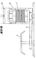
- Fig. 1
- eine erfindungsgemäße Küchenmaschine mit einem Rührgefäß in einer Seitenansicht,
- Fig. 2
- die Küchenmaschine gemäß Figur 1 in Vorderansicht,
- Fig. 3
- die Küchenmaschine in Draufsicht, jedoch nach Abnahme des Rührgefäßes,
- Fig. 4
- die Unteransicht des Rührgefäßes,
- Fig. 5
- eine Ausschnittsvergrößerung des Bereiches V in Figur 1, in Schnittdarstellung,
- Fig. 6
- ein Blockschaltbild einer Heizungssteuerung der Küchenmaschine,
- Fig. 7
- ein Diagramm zur Darstellung einer Temperatursteigung in Abhängigkeit zur Zeit, bezüglich der Heizungssteuerung,
- Fig. 8
- ein weiteres Diagramm zur Darstellung der Leistungsaufnahme in Abhängigkeit zur Zeit, in Bezug auf das Diagramm in Figur 7 und
- Fig. 9
- eine schematische Darstellung eines Rührwerkantriebes mit einer Kühlung.
Claims (12)
- Küchenmaschine mit einem Rührgefäß (6) und einem Antrieb (7) für ein Rührwerk (9) in dem Rührgefäß (6), wobei das Rührgefäß (6) in seinem unteren Bereich aufheizbar ist, wobei weiter eine Rührwerk-Einstellung (Teigrührschaltung) vorgesehen ist, in welcher Rührphasen durch regelmäßige Stillstände unterbrochen sind, dadurch gekennzeichnet, dass die Teigrührschaltung nur aktivierbar ist, wenn die Aufheiztemperatur unterhalb einer bestimmten Grenztemperatur, bspw. 70°C, voreingestellt ist.
- Küchenmaschine nach Anspruch 1, dadurch gekennzeichnet, dass unter Nutzung eines Rührgutwiderstandes eine Reduzierung der sich an sich aus der Leistungsaufnahme ergebenden maximalen Drehzahl auf ein Drittel oder weniger gegeben ist.
- Küchenmaschine nach Anspruch 1 oder 2, dadurch gekennzeichnet, dass die Ruhepausen zur aktiven Kühlung des Antriebsmotors genutzt sind.
- Küchenmaschine nach einem der vorhergehenden Ansprüche, dadurch gekennzeichnet, dass die Stillstände sich im Vergleich zu den Rührphasen etwa über eine dreifache Zeitspanne erstreckt.
- Küchenmaschine nach einem der Ansprüche 1 bis 4, dadurch gekennzeichnet, dass abhängig von einer voreingestellten Drehzahl des Rührwerkes (9) ein Hochfahren des Rührwerkes (9) auf diese Drehzahl zunächst langsam und dann schneller erfolgt.
- Küchenmaschine nach einem der Ansprüche 1 bis 5, dadurch gekennzeichnet, dass eine Aufheizung in Abhängigkeit einer Temperaturanstiegsgeschwindigkeit vorgenommen wird.
- Küchenmaschine nach einem der Ansprüche 1 bis 6, dadurch gekennzeichnet, dass die Aufheizung in Abhängigkeit einer Füllmengenermittlung durchgeführt wird.
- Küchenmaschine nach Anspruch 7, dadurch gekennzeichnet, dass die Füllmengenermittlung durch Vergleich der Temperaturanstiegsgeschwindigkeit bei einer bestimmten Heizleistung mit empirisch bei verschiedenen Füllungen ermittelten Temperaturanstiegswerten durchgeführt wird.
- Küchenmaschine nach Anspruch 7 oder 8, dadurch gekennzeichnet, dass die Füllmengenermittlung weiter in Abhängigkeit der gewählten Drehzahl des Rührwerkes (9) durchgeführt wird.
- Küchenmaschine nach einem der Ansprüche 1 bis 9, dadurch gekennzeichnet, dass ein nicht flüchtiger Speicher vorgesehen ist, in welchem die empirisch ermittelten Werte gespeichert sind.
- Küchenmaschine nach einem der Ansprüche 1 bis 10, dadurch gekennzeichnet, dass Proportionalitätsfaktoren, welche die Aufheizung steuern, je nach gewünschter Endtemperatur unterschiedlich gewählt sind.
- Küchenmaschine nach einem der Ansprüche 1 bis 11, dadurch gekennzeichnet, dass die Aufheizung durch eine elektrische Widerstandsheizung (28) erfolgt und dass die hierfür erforderliche Energieaufnahme jeweils in einem der Leistung angepassten Zeitintervall von beispielsweise 15 Sekunden geregelt ist.
Priority Applications (2)
| Application Number | Priority Date | Filing Date | Title |
|---|---|---|---|
| EP04013318A EP1472962B1 (de) | 1994-04-28 | 1995-04-28 | Küchenmaschine mit einem Rührgefäss und einem Antrieb für ein Rührwerk in dem Rührgefäss |
| EP05109332A EP1616514B1 (de) | 1994-04-28 | 1995-04-28 | Küchenmaschine mit einem Rührgefäß und einem Antrieb für ein Rührwerk in dem Rührgefäß |
Applications Claiming Priority (3)
| Application Number | Priority Date | Filing Date | Title |
|---|---|---|---|
| DE4414825 | 1994-04-28 | ||
| DE4414825A DE4414825A1 (de) | 1994-04-28 | 1994-04-28 | Küchenmaschine mit einem Rührgefäß und einem Antrieb für ein Rührwerk in dem Rührgefäß |
| EP95919365A EP0757529B1 (de) | 1994-04-28 | 1995-04-28 | Küchenmaschine mit einem rührgefäss und einem antrieb für ein rührwerk in dem rührgefäss |
Related Parent Applications (2)
| Application Number | Title | Priority Date | Filing Date |
|---|---|---|---|
| EP95919365A Division EP0757529B1 (de) | 1994-04-28 | 1995-04-28 | Küchenmaschine mit einem rührgefäss und einem antrieb für ein rührwerk in dem rührgefäss |
| EP95919365.7 Division | 1995-11-09 |
Related Child Applications (4)
| Application Number | Title | Priority Date | Filing Date |
|---|---|---|---|
| EP05109332A Division EP1616514B1 (de) | 1994-04-28 | 1995-04-28 | Küchenmaschine mit einem Rührgefäß und einem Antrieb für ein Rührwerk in dem Rührgefäß |
| EP04013318A Division EP1472962B1 (de) | 1994-04-28 | 1995-04-28 | Küchenmaschine mit einem Rührgefäss und einem Antrieb für ein Rührwerk in dem Rührgefäss |
| EP04013318.3 Division-Into | 2004-06-05 | ||
| EP05109332.6 Division-Into | 2005-10-07 |
Publications (3)
| Publication Number | Publication Date |
|---|---|
| EP0966909A2 EP0966909A2 (de) | 1999-12-29 |
| EP0966909A3 EP0966909A3 (de) | 2000-01-05 |
| EP0966909B1 true EP0966909B1 (de) | 2005-11-30 |
Family
ID=6516655
Family Applications (4)
| Application Number | Title | Priority Date | Filing Date |
|---|---|---|---|
| EP99118360A Expired - Lifetime EP0966909B1 (de) | 1994-04-28 | 1995-04-28 | Küchenmaschine mit einem Rührgefäss und einem Antrieb für ein Rührwerk in dem Rührgefäss |
| EP04013318A Expired - Lifetime EP1472962B1 (de) | 1994-04-28 | 1995-04-28 | Küchenmaschine mit einem Rührgefäss und einem Antrieb für ein Rührwerk in dem Rührgefäss |
| EP05109332A Expired - Lifetime EP1616514B1 (de) | 1994-04-28 | 1995-04-28 | Küchenmaschine mit einem Rührgefäß und einem Antrieb für ein Rührwerk in dem Rührgefäß |
| EP95919365A Expired - Lifetime EP0757529B1 (de) | 1994-04-28 | 1995-04-28 | Küchenmaschine mit einem rührgefäss und einem antrieb für ein rührwerk in dem rührgefäss |
Family Applications After (3)
| Application Number | Title | Priority Date | Filing Date |
|---|---|---|---|
| EP04013318A Expired - Lifetime EP1472962B1 (de) | 1994-04-28 | 1995-04-28 | Küchenmaschine mit einem Rührgefäss und einem Antrieb für ein Rührwerk in dem Rührgefäss |
| EP05109332A Expired - Lifetime EP1616514B1 (de) | 1994-04-28 | 1995-04-28 | Küchenmaschine mit einem Rührgefäß und einem Antrieb für ein Rührwerk in dem Rührgefäß |
| EP95919365A Expired - Lifetime EP0757529B1 (de) | 1994-04-28 | 1995-04-28 | Küchenmaschine mit einem rührgefäss und einem antrieb für ein rührwerk in dem rührgefäss |
Country Status (9)
| Country | Link |
|---|---|
| EP (4) | EP0966909B1 (de) |
| AT (4) | ATE194056T1 (de) |
| AU (1) | AU2523395A (de) |
| DE (5) | DE4414825A1 (de) |
| DK (1) | DK0757529T3 (de) |
| ES (4) | ES2290856T3 (de) |
| GR (1) | GR3034422T3 (de) |
| PT (3) | PT1472962E (de) |
| WO (1) | WO1995029614A2 (de) |
Cited By (2)
| Publication number | Priority date | Publication date | Assignee | Title |
|---|---|---|---|---|
| EP3189733A1 (de) | 2016-01-07 | 2017-07-12 | Compania Espanola de Electromenaje, SA | Verfahren zur behandlung von teig und nahrungsmittelemulsionen |
| DE202016102933U1 (de) | 2016-06-01 | 2017-09-04 | Kompernaß Handelsgesellschaft mbH | Küchenmaschine |
Families Citing this family (44)
| Publication number | Priority date | Publication date | Assignee | Title |
|---|---|---|---|---|
| DE29712528U1 (de) * | 1997-07-15 | 1997-09-18 | DEP Corp., Pembroke Pines, Flo. | Vorrichtung zum Homogenisieren und/oder Erwärmen von flüssigen oder breiförmigen Substanzen in einem mit der Vorrichtung verbindbaren Behälter |
| ES2150855B1 (es) * | 1998-06-10 | 2001-06-16 | Hispainox S A | Batidora trituradora electrica para cocinar, de uso domestico. |
| DE102004005607A1 (de) | 2004-02-05 | 2005-09-01 | Vorwerk & Co. Interholding Gmbh | Verfahren zum Zubereiten von Speisen mittels eines Küchengerätes sowie Küchengerät |
| US7499003B2 (en) | 2004-03-31 | 2009-03-03 | Electrolux Home Products, Inc. | Disappearing interface system |
| EP1647217A1 (de) * | 2004-10-15 | 2006-04-19 | Bionicum Establishment | Mehrzweck-Küchengerät |
| US20060286255A1 (en) * | 2005-06-18 | 2006-12-21 | Zhaoxia Xu | Automated Soup Making Apparatus |
| GB2441508A (en) * | 2006-09-08 | 2008-03-12 | Kenwood Ltd | Stand mixer with heating and thermal sensing means |
| DE102006052486A1 (de) * | 2006-11-07 | 2008-05-08 | Robert Bosch Gmbh | Steuerung für eine Waage |
| BRPI0702019A2 (pt) * | 2007-05-10 | 2008-12-23 | Whirlpool Sa | dispositivo de sinalizaÇço para equipamento de preparaÇço de alimentos |
| DE102007031372B4 (de) * | 2007-07-05 | 2013-04-11 | It-Designers Gmbh | Küchenmaschine |
| DE102007053876A1 (de) * | 2007-10-18 | 2009-04-23 | Frank Kaltenbach | Vorrichtung zum Zerkleinern von Lebensmitteln |
| DE102007059236A1 (de) | 2007-12-07 | 2009-06-10 | Vorwerk & Co. Interholding Gmbh | Elektromotorisch betriebene Küchenmaschine |
| GB2457722B (en) * | 2008-02-23 | 2012-02-22 | Kenwood Ltd | Improvements in or relating to food mixers and processors |
| DE102008040935A1 (de) * | 2008-08-01 | 2010-02-04 | BSH Bosch und Siemens Hausgeräte GmbH | Küchengerät mit Motordrehzahlanzeige |
| DE102009050693A1 (de) * | 2009-10-26 | 2011-04-28 | Ralph Schelle | Drehzahlgeregelter Lüfter |
| EP2345350B1 (de) * | 2010-01-18 | 2013-10-30 | BSH Bosch und Siemens Hausgeräte GmbH | Gargerätevorrichtung |
| DE102010000299B4 (de) | 2010-02-04 | 2019-02-21 | Vorwerk & Co. Interholding Gmbh | Küchenmaschine |
| HRPK20100125B3 (hr) * | 2010-03-05 | 2012-12-31 | Ksenija Kralj | Ureä�aj za pripremu slastica i hrane na pari |
| DE102010016024B4 (de) * | 2010-03-19 | 2018-02-22 | Vorwerk & Co. Interholding Gmbh | Küchenmaschine |
| US8720325B2 (en) | 2010-04-29 | 2014-05-13 | Whirlpool Corporation | Food processor with a lockable adjustable blade assembly |
| US10449685B2 (en) | 2010-04-29 | 2019-10-22 | Whirlpool Corporation | Food processor with adjustable blade assembly |
| EP2388564A1 (de) | 2010-05-20 | 2011-11-23 | Koninklijke Philips Electronics N.V. | Schätzen der Temperatur |
| DE102010017335A1 (de) * | 2010-06-11 | 2011-12-15 | Vorwerk & Co. Interholding Gmbh | Küchenmaschine mit einem Rührgefäß sowie Verfahren zum Betreiben einer solchen Küchenmaschine |
| DE102010037769B4 (de) * | 2010-09-24 | 2019-09-19 | Vorwerk & Co. Interholding Gmbh | Elektrisch betriebene Küchenmaschine sowie Verfahren zum Betreiben einer solchen Küchenmaschine |
| DE102012103882A1 (de) * | 2011-05-11 | 2012-11-15 | Vorwerk & Co. Interholding Gmbh | Verfahren zum Zubereiten von Speisen in einem Gargefäß sowie elektrische Küchenmaschine mit einem Gargefäß |
| EP2564735A1 (de) | 2011-08-31 | 2013-03-06 | Koninklijke Philips Electronics N.V. | Heizung |
| CN102359834B (zh) * | 2011-09-06 | 2014-06-25 | 际华三五零二职业装有限公司 | 多点自控恒温检温装置 |
| DE102012103877A1 (de) | 2012-05-03 | 2013-11-07 | Vorwerk & Co. Interholding Gmbh | Deckel für ein Gargefäß sowie Gargefäß mit einem Deckel |
| DE202012105011U1 (de) | 2012-12-21 | 2013-01-25 | Vorwerk & Co. Interholding Gmbh | Elektromotorisch betriebene Küchenmaschine |
| US10413109B2 (en) | 2013-03-13 | 2019-09-17 | Spectrum Brands, Inc. | Food preparation appliance for steam cooking and food processing |
| DE102014115346A1 (de) | 2014-10-21 | 2016-05-04 | Vorwerk & Co. Interholding Gmbh | Verfahren und Küchenmaschine zum Zubereiten eines Zubereitungsguts |
| US10085599B2 (en) | 2014-12-19 | 2018-10-02 | Whirlpool Corporation | Multi-cook and food processing prep product |
| DE102015103596A1 (de) * | 2015-03-11 | 2016-09-15 | Vorwerk & Co. Interholding Gmbh | Verfahren zum Betrieb einer elektromotorisch angetriebenen Küchenmaschine |
| ES2807562T3 (es) | 2015-09-18 | 2021-02-23 | Vorwerk Co Interholding | Sistema y método para mejorar la reproducibilidad de los resultados de la cocción de un aparato de cocina multifuncional |
| USD853782S1 (en) | 2017-02-20 | 2019-07-16 | Whirlpool Corporation | Food processor |
| CN106665725A (zh) * | 2017-02-20 | 2017-05-17 | 刘魁 | 一种揉面效果好的面条机 |
| DE102018203719B4 (de) * | 2018-03-13 | 2025-10-30 | Vorwerk & Co. Interholding Gmbh | Haushaltsküchenmaschine |
| US10966506B2 (en) | 2018-10-30 | 2021-04-06 | Rea Innovations, Inc. | Dual-piston appliance for processing of cosmetic formulations |
| CA3142059A1 (en) | 2019-05-28 | 2020-12-03 | Sharkninja Operating Llc | Heated food processor |
| US11497692B2 (en) | 2019-10-15 | 2022-11-15 | Rea Innovations, Inc. | Systems and methods for blending solid-shell cosmetic ingredient capsules and blendable cosmetic ingredient capsules |
| US11660578B2 (en) | 2019-10-15 | 2023-05-30 | Rea Innovations, Inc. | Systems and methods for blending solid-shell cosmetic ingredient capsules and blendable cosmetic ingredient capsules |
| USD986498S1 (en) | 2020-03-04 | 2023-05-16 | Rea Innovations, Inc. | Cosmetic appliance |
| CN112386094B (zh) * | 2020-12-01 | 2022-06-28 | 珠海优特智厨科技有限公司 | 一种烹饪器具的控制方法以及烹饪系统 |
| WO2022212021A1 (en) * | 2021-04-02 | 2022-10-06 | Ascent Technology, LLC | Artificial gravity heating device |
Family Cites Families (10)
| Publication number | Priority date | Publication date | Assignee | Title |
|---|---|---|---|---|
| US4323110A (en) * | 1977-01-11 | 1982-04-06 | Anchor Hocking Corporation | Food preparation process |
| GB1544035A (en) * | 1978-03-20 | 1979-04-11 | Diamond H Controls Ltd | Means for presetting and adjusting the hours and minute settings on electronically controlled timing mechanisms |
| DE3430993A1 (de) * | 1984-08-23 | 1986-03-06 | Miele & Cie GmbH & Co, 4830 Gütersloh | Optische schaltstufenanzeige fuer drehwahlschalter von haushaltsgeraeten, insbesondere von herden |
| DE3507276C2 (de) * | 1985-03-01 | 1987-01-08 | Vorwerk & Co Interholding Gmbh, 5600 Wuppertal | Elektromotorisch betriebenes Haushaltsmixgerät |
| JPH0523180Y2 (de) * | 1989-01-13 | 1993-06-14 | ||
| US5274216A (en) * | 1989-08-15 | 1993-12-28 | Aladdin Synergetics, Inc. | Food rethermalizing and satelliting tray |
| JPH04148635A (ja) * | 1990-10-11 | 1992-05-21 | Taisho Denki Hanbai Kk | パン生地こね方法 |
| JPH04244521A (ja) * | 1991-01-29 | 1992-09-01 | Toshiba Corp | 加熱調理器 |
| DE4115471A1 (de) | 1991-05-11 | 1992-11-12 | Braun Ag | Elektrisch betriebene kuechenmaschine |
| JP2848015B2 (ja) * | 1991-05-17 | 1999-01-20 | 松下電器産業株式会社 | 調理器 |
-
1994
- 1994-04-28 DE DE4414825A patent/DE4414825A1/de not_active Ceased
-
1995
- 1995-04-28 ES ES05109332T patent/ES2290856T3/es not_active Expired - Lifetime
- 1995-04-28 PT PT04013318T patent/PT1472962E/pt unknown
- 1995-04-28 ES ES99118360T patent/ES2252900T3/es not_active Expired - Lifetime
- 1995-04-28 ES ES04013318T patent/ES2262067T3/es not_active Expired - Lifetime
- 1995-04-28 EP EP99118360A patent/EP0966909B1/de not_active Expired - Lifetime
- 1995-04-28 DE DE59511084T patent/DE59511084D1/de not_active Expired - Fee Related
- 1995-04-28 EP EP04013318A patent/EP1472962B1/de not_active Expired - Lifetime
- 1995-04-28 AT AT95919365T patent/ATE194056T1/de not_active IP Right Cessation
- 1995-04-28 WO PCT/EP1995/001637 patent/WO1995029614A2/de not_active Ceased
- 1995-04-28 AT AT04013318T patent/ATE329512T1/de not_active IP Right Cessation
- 1995-04-28 EP EP05109332A patent/EP1616514B1/de not_active Expired - Lifetime
- 1995-04-28 EP EP95919365A patent/EP0757529B1/de not_active Expired - Lifetime
- 1995-04-28 DK DK95919365T patent/DK0757529T3/da active
- 1995-04-28 PT PT05109332T patent/PT1616514E/pt unknown
- 1995-04-28 AU AU25233/95A patent/AU2523395A/en not_active Abandoned
- 1995-04-28 ES ES95919365T patent/ES2148519T3/es not_active Expired - Lifetime
- 1995-04-28 AT AT99118360T patent/ATE311137T1/de not_active IP Right Cessation
- 1995-04-28 DE DE59508516T patent/DE59508516D1/de not_active Expired - Lifetime
- 1995-04-28 DE DE59511026T patent/DE59511026D1/de not_active Expired - Lifetime
- 1995-04-28 DE DE59511052T patent/DE59511052D1/de not_active Expired - Fee Related
- 1995-04-28 AT AT05109332T patent/ATE374553T1/de not_active IP Right Cessation
- 1995-04-28 PT PT95919365T patent/PT757529E/pt unknown
-
2000
- 2000-09-18 GR GR20000402110T patent/GR3034422T3/el not_active IP Right Cessation
Cited By (2)
| Publication number | Priority date | Publication date | Assignee | Title |
|---|---|---|---|---|
| EP3189733A1 (de) | 2016-01-07 | 2017-07-12 | Compania Espanola de Electromenaje, SA | Verfahren zur behandlung von teig und nahrungsmittelemulsionen |
| DE202016102933U1 (de) | 2016-06-01 | 2017-09-04 | Kompernaß Handelsgesellschaft mbH | Küchenmaschine |
Also Published As
| Publication number | Publication date |
|---|---|
| ATE329512T1 (de) | 2006-07-15 |
| EP0966909A2 (de) | 1999-12-29 |
| GR3034422T3 (en) | 2000-12-29 |
| WO1995029614A3 (de) | 1995-11-30 |
| WO1995029614A2 (de) | 1995-11-09 |
| DE59511026D1 (de) | 2006-01-05 |
| ATE194056T1 (de) | 2000-07-15 |
| ES2290856T3 (es) | 2008-02-16 |
| ES2148519T3 (es) | 2000-10-16 |
| EP1472962A1 (de) | 2004-11-03 |
| ATE311137T1 (de) | 2005-12-15 |
| EP1472962B1 (de) | 2006-06-14 |
| DE59508516D1 (de) | 2000-08-03 |
| PT1616514E (pt) | 2007-11-15 |
| EP0757529B1 (de) | 2000-06-28 |
| AU2523395A (en) | 1995-11-29 |
| ES2262067T3 (es) | 2006-11-16 |
| ATE374553T1 (de) | 2007-10-15 |
| EP1616514B1 (de) | 2007-10-03 |
| ES2252900T3 (es) | 2006-05-16 |
| EP0966909A3 (de) | 2000-01-05 |
| DE4414825A1 (de) | 1995-11-02 |
| EP0757529A1 (de) | 1997-02-12 |
| DK0757529T3 (da) | 2000-11-06 |
| PT1472962E (pt) | 2006-08-31 |
| PT757529E (pt) | 2000-10-31 |
| DE59511052D1 (de) | 2006-07-27 |
| DE59511084D1 (de) | 2007-11-15 |
| EP1616514A1 (de) | 2006-01-18 |
Similar Documents
| Publication | Publication Date | Title |
|---|---|---|
| EP0757529B1 (de) | Küchenmaschine mit einem rührgefäss und einem antrieb für ein rührwerk in dem rührgefäss | |
| DE3650352T2 (de) | Vorrichtung zur Herstellung von Brot. | |
| EP2874526B1 (de) | Küchenmaschine | |
| DE3879368T2 (de) | Reglervorrichtung fuer einen ofen. | |
| EP2460452A1 (de) | Küchenmaschine mit einem Rührgefäß | |
| DE69704454T2 (de) | Küchengerät | |
| DE3485991T2 (de) | Knetvorrichtung fuer eine vorrichtung zum backen von brot. | |
| DE69331468T2 (de) | Verfahren und vorrichtung zum conchieren von schokolade | |
| DE60013682T2 (de) | Ofen zum Toasten | |
| WO2016142405A1 (de) | Verfahren zum betrieb einer elektromotorisch angetriebenen küchenmaschine | |
| DE102010037769A1 (de) | Elektrisch betriebene Küchenmaschine sowie Verfahren zum Betreiben einer solchen Küchenmaschine | |
| EP0556467A1 (de) | Vielzweckküchenmaschine | |
| EP3936016A1 (de) | Speisenzubereitungsgerät zum schneiden von lebensmitteln | |
| DE102015216678B4 (de) | Handgehaltenes elektrisch angetriebenes Haushaltsgerät mit Modiauswahl | |
| DE60214214T2 (de) | Vorrichtung und verfahren zum kochen von nahrungsmitteln mit mikrowellen | |
| EP0573759B1 (de) | Zufuhrregelung eines Fleischwolfes | |
| DE2145096C (de) | Einrichtung zur automatischen Mahlspalt-Steuerung bei einer Mühle | |
| EP4494536A2 (de) | Speisenzubereitungsgerät zum schneiden von lebensmitteln, zerkleinerungsaufsatz und verfahren | |
| CH664480A5 (de) | Mobiler mixer mit stufenloser drehzahlregulierung und zuschaltbarer heizung. | |
| DE2145096B1 (de) | Einrichtung zur automatischen mahlspalt-steuerung bei einer muehle | |
| DE69600233T2 (de) | Küchenmachine mit einem Arbeitsgefäss mit einer Vorrichtung zum Reinigen der Innenwandung des Arbeitsgefässes | |
| DE69700921T2 (de) | Kochgerät mit mehreren Kochleistungen | |
| EP3771381B1 (de) | Automatische abschalteinrichtung für ein küchengerät, küchengerät und verfahren | |
| DE1299983B (de) | Verfahren zum Betrieb einer Mahlanlage | |
| DE102023003998A1 (de) | Softwaregesteuertes Verfahren zur Konditionierung von Material wie schmelzbare Lebensmittel |
Legal Events
| Date | Code | Title | Description |
|---|---|---|---|
| PUAI | Public reference made under article 153(3) epc to a published international application that has entered the european phase |
Free format text: ORIGINAL CODE: 0009012 |
|
| PUAL | Search report despatched |
Free format text: ORIGINAL CODE: 0009013 |
|
| AC | Divisional application: reference to earlier application |
Ref document number: 757529 Country of ref document: EP |
|
| AK | Designated contracting states |
Kind code of ref document: A2 Designated state(s): AT BE CH DE DK ES FR GB GR IE IT LI LU MC NL PT SE |
|
| AX | Request for extension of the european patent |
Free format text: LT PAYMENT 19991007;SI PAYMENT 19991007 |
|
| AK | Designated contracting states |
Kind code of ref document: A3 Designated state(s): AT BE CH DE DK ES FR GB GR IE IT LI LU MC NL PT SE |
|
| AX | Request for extension of the european patent |
Free format text: LT PAYMENT 19991007;SI PAYMENT 19991007 |
|
| RTI1 | Title (correction) |
Free format text: FOOD PROCESSOR WITH A MIXING VESSEL AND A DRIVE MECHANISM FOR AN AGITATOR IN THE MIXING VESSEL |
|
| RTI1 | Title (correction) |
Free format text: FOOD PROCESSOR WITH A MIXING VESSEL AND A DRIVE MECHANISM FOR AN AGITATOR IN THE MIXING VESSEL |
|
| 17P | Request for examination filed |
Effective date: 20000630 |
|
| AKX | Designation fees paid |
Free format text: AT BE CH DE DK ES FR GB GR IE IT LI LU MC NL PT SE |
|
| AXX | Extension fees paid |
Free format text: LT PAYMENT 19991007;SI PAYMENT 19991007 |
|
| 17Q | First examination report despatched |
Effective date: 20031217 |
|
| GRAP | Despatch of communication of intention to grant a patent |
Free format text: ORIGINAL CODE: EPIDOSNIGR1 |
|
| GRAS | Grant fee paid |
Free format text: ORIGINAL CODE: EPIDOSNIGR3 |
|
| GRAA | (expected) grant |
Free format text: ORIGINAL CODE: 0009210 |
|
| AC | Divisional application: reference to earlier application |
Ref document number: 0757529 Country of ref document: EP Kind code of ref document: P |
|
| AK | Designated contracting states |
Kind code of ref document: B1 Designated state(s): AT BE CH DE DK ES FR GB GR IE IT LI LU MC NL PT SE |
|
| AX | Request for extension of the european patent |
Extension state: LT SI |
|
| PG25 | Lapsed in a contracting state [announced via postgrant information from national office to epo] |
Ref country code: NL Free format text: LAPSE BECAUSE OF FAILURE TO SUBMIT A TRANSLATION OF THE DESCRIPTION OR TO PAY THE FEE WITHIN THE PRESCRIBED TIME-LIMIT Effective date: 20051130 Ref country code: IE Free format text: LAPSE BECAUSE OF FAILURE TO SUBMIT A TRANSLATION OF THE DESCRIPTION OR TO PAY THE FEE WITHIN THE PRESCRIBED TIME-LIMIT Effective date: 20051130 Ref country code: GB Free format text: LAPSE BECAUSE OF FAILURE TO SUBMIT A TRANSLATION OF THE DESCRIPTION OR TO PAY THE FEE WITHIN THE PRESCRIBED TIME-LIMIT Effective date: 20051130 |
|
| REG | Reference to a national code |
Ref country code: GB Ref legal event code: FG4D Free format text: NOT ENGLISH Ref country code: CH Ref legal event code: EP |
|
| REG | Reference to a national code |
Ref country code: IE Ref legal event code: FG4D Free format text: LANGUAGE OF EP DOCUMENT: GERMAN |
|
| REF | Corresponds to: |
Ref document number: 59511026 Country of ref document: DE Date of ref document: 20060105 Kind code of ref document: P |
|
| PG25 | Lapsed in a contracting state [announced via postgrant information from national office to epo] |
Ref country code: SE Free format text: LAPSE BECAUSE OF FAILURE TO SUBMIT A TRANSLATION OF THE DESCRIPTION OR TO PAY THE FEE WITHIN THE PRESCRIBED TIME-LIMIT Effective date: 20060228 Ref country code: DK Free format text: LAPSE BECAUSE OF FAILURE TO SUBMIT A TRANSLATION OF THE DESCRIPTION OR TO PAY THE FEE WITHIN THE PRESCRIBED TIME-LIMIT Effective date: 20060228 |
|
| PG25 | Lapsed in a contracting state [announced via postgrant information from national office to epo] |
Ref country code: MC Free format text: LAPSE BECAUSE OF NON-PAYMENT OF DUE FEES Effective date: 20060430 Ref country code: LI Free format text: LAPSE BECAUSE OF NON-PAYMENT OF DUE FEES Effective date: 20060430 Ref country code: CH Free format text: LAPSE BECAUSE OF NON-PAYMENT OF DUE FEES Effective date: 20060430 Ref country code: BE Free format text: LAPSE BECAUSE OF NON-PAYMENT OF DUE FEES Effective date: 20060430 |
|
| REG | Reference to a national code |
Ref country code: GR Ref legal event code: EP Ref document number: 20060400524 Country of ref document: GR |
|
| REG | Reference to a national code |
Ref country code: ES Ref legal event code: FG2A Ref document number: 2252900 Country of ref document: ES Kind code of ref document: T3 |
|
| LTIE | Lt: invalidation of european patent or patent extension |
Effective date: 20051130 |
|
| NLV1 | Nl: lapsed or annulled due to failure to fulfill the requirements of art. 29p and 29m of the patents act | ||
| GBV | Gb: ep patent (uk) treated as always having been void in accordance with gb section 77(7)/1977 [no translation filed] |
Effective date: 20051130 |
|
| ET | Fr: translation filed | ||
| REG | Reference to a national code |
Ref country code: IE Ref legal event code: FD4D |
|
| PLBE | No opposition filed within time limit |
Free format text: ORIGINAL CODE: 0009261 |
|
| STAA | Information on the status of an ep patent application or granted ep patent |
Free format text: STATUS: NO OPPOSITION FILED WITHIN TIME LIMIT |
|
| 26N | No opposition filed |
Effective date: 20060831 |
|
| REG | Reference to a national code |
Ref country code: CH Ref legal event code: PL |
|
| PGFP | Annual fee paid to national office [announced via postgrant information from national office to epo] |
Ref country code: AT Payment date: 20070406 Year of fee payment: 13 |
|
| BERE | Be: lapsed |
Owner name: VORWERK & CO. INTERHOLDING G.M.B.H. Effective date: 20060430 |
|
| PGFP | Annual fee paid to national office [announced via postgrant information from national office to epo] |
Ref country code: GR Payment date: 20070315 Year of fee payment: 13 |
|
| PG25 | Lapsed in a contracting state [announced via postgrant information from national office to epo] |
Ref country code: LU Free format text: LAPSE BECAUSE OF NON-PAYMENT OF DUE FEES Effective date: 20060428 |
|
| PG25 | Lapsed in a contracting state [announced via postgrant information from national office to epo] |
Ref country code: AT Free format text: LAPSE BECAUSE OF NON-PAYMENT OF DUE FEES Effective date: 20080428 |
|
| PG25 | Lapsed in a contracting state [announced via postgrant information from national office to epo] |
Ref country code: GR Free format text: LAPSE BECAUSE OF NON-PAYMENT OF DUE FEES Effective date: 20081104 |
|
| PGFP | Annual fee paid to national office [announced via postgrant information from national office to epo] |
Ref country code: PT Payment date: 20140319 Year of fee payment: 20 |
|
| PGFP | Annual fee paid to national office [announced via postgrant information from national office to epo] |
Ref country code: IT Payment date: 20140423 Year of fee payment: 20 Ref country code: FR Payment date: 20140408 Year of fee payment: 20 Ref country code: DE Payment date: 20140409 Year of fee payment: 20 Ref country code: ES Payment date: 20140410 Year of fee payment: 20 |
|
| REG | Reference to a national code |
Ref country code: DE Ref legal event code: R071 Ref document number: 59511026 Country of ref document: DE |
|
| REG | Reference to a national code |
Ref country code: PT Ref legal event code: MM4A Free format text: MAXIMUM VALIDITY LIMIT REACHED Effective date: 20150428 |
|
| REG | Reference to a national code |
Ref country code: ES Ref legal event code: FD2A Effective date: 20150703 |
|
| PG25 | Lapsed in a contracting state [announced via postgrant information from national office to epo] |
Ref country code: ES Free format text: LAPSE BECAUSE OF EXPIRATION OF PROTECTION Effective date: 20150429 Ref country code: PT Free format text: LAPSE BECAUSE OF EXPIRATION OF PROTECTION Effective date: 20150506 |