EP0966625B1 - Kettenschloss - Google Patents
Kettenschloss Download PDFInfo
- Publication number
- EP0966625B1 EP0966625B1 EP97918023A EP97918023A EP0966625B1 EP 0966625 B1 EP0966625 B1 EP 0966625B1 EP 97918023 A EP97918023 A EP 97918023A EP 97918023 A EP97918023 A EP 97918023A EP 0966625 B1 EP0966625 B1 EP 0966625B1
- Authority
- EP
- European Patent Office
- Prior art keywords
- holding teeth
- pairs
- limbs
- region
- holding
- Prior art date
- Legal status (The legal status is an assumption and is not a legal conclusion. Google has not performed a legal analysis and makes no representation as to the accuracy of the status listed.)
- Expired - Lifetime
Links
- 230000007704 transition Effects 0.000 claims description 5
- 238000003825 pressing Methods 0.000 claims description 4
- 230000002787 reinforcement Effects 0.000 claims 1
- 210000002414 leg Anatomy 0.000 description 14
- 238000009826 distribution Methods 0.000 description 3
- 230000002349 favourable effect Effects 0.000 description 2
- 238000005457 optimization Methods 0.000 description 2
- 230000009286 beneficial effect Effects 0.000 description 1
- 238000007596 consolidation process Methods 0.000 description 1
- 238000010276 construction Methods 0.000 description 1
- 238000005336 cracking Methods 0.000 description 1
- 230000001419 dependent effect Effects 0.000 description 1
- 210000003414 extremity Anatomy 0.000 description 1
- 238000003892 spreading Methods 0.000 description 1
- 210000000689 upper leg Anatomy 0.000 description 1
Images
Classifications
-
- F—MECHANICAL ENGINEERING; LIGHTING; HEATING; WEAPONS; BLASTING
- F16—ENGINEERING ELEMENTS AND UNITS; GENERAL MEASURES FOR PRODUCING AND MAINTAINING EFFECTIVE FUNCTIONING OF MACHINES OR INSTALLATIONS; THERMAL INSULATION IN GENERAL
- F16G—BELTS, CABLES, OR ROPES, PREDOMINANTLY USED FOR DRIVING PURPOSES; CHAINS; FITTINGS PREDOMINANTLY USED THEREFOR
- F16G15/00—Chain couplings, Shackles; Chain joints; Chain links; Chain bushes
- F16G15/02—Chain couplings, Shackles; Chain joints; Chain links; Chain bushes for fastening more or less permanently
Definitions
- the invention relates to a chain lock for link chains essentially with two detachably connected U-shaped lock parts, each with an inner leg and an outer leg connected to it via a yoke have, wherein in the closed position of the Lock the mutually facing sides of the interior and The outer legs are joined together by three pairs of retaining teeth connected and in the range of stronger than that remaining holding teeth trained holding teeth of the middle Holding tooth pairs between the facing sides the inner leg is a support and locking element for the lock parts is arranged.
- a chain lock of the above type is related to its basic structure known from DE 32 07 629 C2.
- the well-known chain lock is characterized by a favorable distribution of the forces to be transmitted to the different pairs of holding teeth.
- beneficial Training are those with the well-known castle achievable strength values are still noticeably smaller than the strength values over which the limbs of the to connecting chain strands.
- different paths were taken.
- the invention has for its object the strength the generic chain lock by suitable measures to further increase in terms of optimization in order to the service life of the lock and chains even more than so far to align with each other and so in particular claims of underground construction after reducing the frequency an exchange of chain locks in high stressed drive chains under difficult conditions To take into account.
- the task is solved by the combination of the characteristics of the first speech.
- the proposed height ratios achieve that wear of the outer legs of the castle less quickly than before to weaken the Lock strength leads.
- the structure of the investment relationships caused between the flanks of the holding teeth a more favorable tension distribution in the castle and this especially in the case of heavy loads.
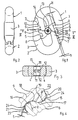
- Fig. 1, 1 and 2 are two identical shapes, essentially designated U-shaped lock parts, each of which has an outer leg 3 and one Inner leg 4 has.
- the outer legs have three Holding teeth 5,6 and 7 and the inner thighs three holding teeth 8.9 and 10.
- the mutually facing surfaces of the inner legs 4 are provided with locking recesses 11 in the as spring washers trained expansion elements 12 can snap through a cylindrical support member 13 in the locked position is held.
- the spreading elements 12 into the interior of grooves of the support element 13 immerse. 14 is a rotation lock of the Support element.
- Fig. 4 are the investment conditions on an enlarged scale shown between the holding teeth 6 and 9.
- the tooth flanks 15, 16 only along one between the small circles drawn in FIG. 4 17,18 lying support zone 19 against each other. Cavities 20, 21 are arranged on both sides of the support zone 19.
- the design of the tooth flanks 15, 16 described offers the guarantee that introduced into the chain lock Tractive forces on a well-defined, affordable Position to be transferred.
- In the area of the transitions of the Tooth flanks 15, 16 in the respective tooth base 22 or 23 is a series of slightly overlapping dents indicated by dashed lines 24 arranged.
- the dents 24 are with by pressing in a tool a dome designed as a pressure stamp in the tooth base generated. Due to the plastic deformation of the tooth base in the area of the dents 24, permanent compressive stress. When the chain lock is loaded must be due to the external acting Normal tensile stresses that arise from these forces Overcome compressive stresses before they reach a level that can lead to harmful cracking. Through the plastic Deformation of the tooth base becomes significant Increasing the dynamic strength of the chain lock reached.
- the dents 24 preferably have the negative form of one Section of an ellipsoid, whose semiaxes in the case of a spherical tool can be the same. About that but there are also truncated pyramids, tapered or frustoconical printing tools for producing the dents 24 into consideration.
- the depth t the impressions formed by the dents 24 should at least 2% and at most 20% of the radius R in the range of Transition of the tooth flanks into the tooth base and the smallest distance between the centers of neighboring Dents in the order of 5 to 15% of this radius R lie.
Landscapes
- Engineering & Computer Science (AREA)
- General Engineering & Computer Science (AREA)
- Mechanical Engineering (AREA)
- Devices For Conveying Motion By Means Of Endless Flexible Members (AREA)
- Clamps And Clips (AREA)
- Control Of Throttle Valves Provided In The Intake System Or In The Exhaust System (AREA)
- Valve Device For Special Equipments (AREA)
- Materials For Photolithography (AREA)
- Orthopedics, Nursing, And Contraception (AREA)
Description
Claims (7)
- Kettenschloß für Gliederketten mit zwei lösbar miteinander verbundenen im wesentlichen U-förmigen Schloßteilen (1,2) die jeweils einen Inneschenkel (4) und einen mit diesem über ein Joch verbundenen Außenschenkel (3) aufweisen, wobei in der Schließstellung des Schlosses die einander zugewandten Seiten der Innen- und Außenschenkel durch jeweils drei Haltezahnpaare miteinander verbunden sind und im Bereich der kräftiger als die übrigen Haltezähne ausgebildeten Haltezähne (6,9) der mittleren Haltezahnpaare zwischen den einander zugewandten Seiten der Innenschenkel (4) ein Stütz- und Verriegelungselement (12,13) für die Schloßteile (1,2) angeordnet ist, wobei die Haltezähne (6,9) der mittleren Haltezahnpaare eine größere Höhe (H) als die Haltezähne (7,10) der im Bereich der Enden der Außenschenkel (3) angeordneten Haltezahnpaare haben und wobei zwischen den Flanken der jeweils miteinander in Eingriff stehenden Haltezähne eines jeden Haltezahnpaares beidseits einer sich über einen Teil der Höhe der Haltezähne erstreckenden zur Übertragung von Längskräften dienenden zentralen Stützzone (19) Hohlräume (20,21) vorgesehen sind, dadurch gekennzeichnet, daß auch die Haltezähne (5,8) der im Bereich der Enden der Innenschenkel (4) angeordneten Haltezahnpaare eine größere Höhe (H) als die Haltezähne (7,10) der im Bereich der Enden der Außenschenkel (3) angeordneten Haltezahnpaare haben und daß sich die zentrale Stützzone (19) höchstens über ein Drittel der Höhe der Haltezähne (5-10) erstreckt.
- Kettenschloß nach Anspruch 1, dadurch gekennzeichnet, daß die zentralen Stützzonen (19) eine schwach S-förmige Kontur haben.
- Kettenschloß nach Anspruch 1 oder 2, dadurch gekennzeichnet, daß die Zahnflanken (15,16) sich lediglich im Bereich der zentralen Stützzonen (19) berühren.
- Kettenschloß nach einem oder mehreren der Ansprüche 1 bis 3, dadurch gekennzeichnet, daß die den Innenschenkeln (4) zugewandten Flächen der Außenschenkel (3) konkav sind und die den Außenschenkeln (3) zugewandten Flächen der Innenschenkel (4) konvex ausgebildet sind, oder umgekehrt.
- Kettenschloß nach einem oder mehreren der Ansprüche 1 bis 4, dadurch gekennzeichnet, daß sämtliche Haltezähne (5-10) im Bereich des Überganges ihrer Zahnflanken (15,16) in den Zahnlückenbereich der Innen- und Außenschenkel (3,4) zwecks Oberflächenverfestigung mit Hilfe eines Druckwerkzeuges mit einem kugelförmigen Druckkopf plastisch verformt sind, wobei die durch den Druckkopf erzeugten, sich seitlich überlappenden Dellen (24)- einen Radius aufweisen, der 85 bis 95% des Zahngrundradius (R) beträgt.
- Kettenschloß nach Anspruch 5, dadurch gekennzeichnet, daß der kleinste Abstand zwischen den Zentren der jeweils benachbarten Dellen (24) etwa 5 bis 15% des Zahngrundradius (R) beträgt.
- Kettenschloß nach Anspruch 5 oder 6, dadurch gekennzeichnet, daß die Tiefe (t) der Dellen (24) mindestens 2% und höchstens 20% des Zahngrundradius (R) beträgt.
Applications Claiming Priority (1)
| Application Number | Priority Date | Filing Date | Title |
|---|---|---|---|
| PCT/DE1997/000514 WO1998040646A1 (de) | 1997-03-10 | 1997-03-10 | Kettenschloss |
Publications (2)
| Publication Number | Publication Date |
|---|---|
| EP0966625A1 EP0966625A1 (de) | 1999-12-29 |
| EP0966625B1 true EP0966625B1 (de) | 2001-09-05 |
Family
ID=6918478
Family Applications (1)
| Application Number | Title | Priority Date | Filing Date |
|---|---|---|---|
| EP97918023A Expired - Lifetime EP0966625B1 (de) | 1997-03-10 | 1997-03-10 | Kettenschloss |
Country Status (6)
| Country | Link |
|---|---|
| US (1) | US6216434B1 (de) |
| EP (1) | EP0966625B1 (de) |
| AT (1) | ATE205285T1 (de) |
| AU (1) | AU728159B2 (de) |
| DE (1) | DE59704560D1 (de) |
| WO (1) | WO1998040646A1 (de) |
Families Citing this family (6)
| Publication number | Priority date | Publication date | Assignee | Title |
|---|---|---|---|---|
| DE20120032U1 (de) * | 2000-12-16 | 2002-05-16 | J. D. Theile GmbH & Co KG, 58239 Schwerte | Kettenschloß sowie Mittelstück für ein Kettenglied oder ein solches Kettenschloß |
| DE202006016032U1 (de) * | 2006-10-16 | 2006-12-21 | Thiele Gmbh & Co. Kg | Kettenverbindungsglied |
| DE202009007749U1 (de) | 2009-05-30 | 2010-09-16 | Jasper, Ingo, Dr. | Kettenschloss |
| BR112014003320A2 (pt) | 2011-08-30 | 2017-07-18 | Esco Corp | elos de acoplamento e corrente |
| DE202012103455U1 (de) * | 2012-09-11 | 2012-09-28 | Thiele Gmbh & Co. Kg | Kettenverbindungselement mit Sicherungssteg |
| DE102016108050A1 (de) * | 2016-04-29 | 2017-11-02 | Schmiedestück-Vertrieb Feuerstein Gmbh | Kenterschäkel |
Family Cites Families (5)
| Publication number | Priority date | Publication date | Assignee | Title |
|---|---|---|---|---|
| US2819586A (en) * | 1951-06-22 | 1958-01-14 | Pierre Henry St | Joiner link with two part bracing means having stop means thereon |
| DE3207629C2 (de) * | 1982-02-26 | 1983-12-15 | Rud-Kettenfabrik Rieger & Dietz Gmbh U. Co, 7080 Aalen | Kettenschloß für Gliederketten |
| DE3710047A1 (de) * | 1987-03-27 | 1988-10-06 | Wollbrecht Gisbert | Kettenverbindungsglied zur loesbaren verbindung von rundgliederketten |
| DE3916284A1 (de) * | 1989-05-19 | 1990-11-22 | Becker Pruente Gmbh | Kettenschloss fuer rundgliederketten |
| DE4333261C1 (de) * | 1993-09-27 | 1994-10-27 | Rud Ketten Rieger & Dietz | Kettenschloß |
-
1997
- 1997-03-10 AU AU26323/97A patent/AU728159B2/en not_active Ceased
- 1997-03-10 US US09/367,565 patent/US6216434B1/en not_active Expired - Lifetime
- 1997-03-10 EP EP97918023A patent/EP0966625B1/de not_active Expired - Lifetime
- 1997-03-10 WO PCT/DE1997/000514 patent/WO1998040646A1/de not_active Ceased
- 1997-03-10 DE DE59704560T patent/DE59704560D1/de not_active Expired - Lifetime
- 1997-03-10 AT AT97918023T patent/ATE205285T1/de active
Also Published As
| Publication number | Publication date |
|---|---|
| US6216434B1 (en) | 2001-04-17 |
| WO1998040646A1 (de) | 1998-09-17 |
| EP0966625A1 (de) | 1999-12-29 |
| ATE205285T1 (de) | 2001-09-15 |
| DE59704560D1 (de) | 2001-10-11 |
| AU728159B2 (en) | 2001-01-04 |
| AU2632397A (en) | 1998-09-29 |
Similar Documents
| Publication | Publication Date | Title |
|---|---|---|
| EP1555234A1 (de) | Aufzugsanlage | |
| DE60004532T2 (de) | Gummigleiskette | |
| DE19647322A1 (de) | Kettenglied aus verschiedenen Werkstoffen und Verfahren zu dessen Herstellung | |
| EP1307670B1 (de) | Kette und kettentrieb für ein hebezeug | |
| DE3207629A1 (de) | Kettenschloss fuer gliederketten | |
| DE102015214395A1 (de) | Gurt oder Gurtsegment | |
| DE10211308A1 (de) | Zahnkette | |
| DE2614691B2 (de) | Gleiskette | |
| DE4332447A1 (de) | Kettenriemen | |
| DE2912027A1 (de) | Einrichtung zum schutz von ankerketten | |
| DE3201840A1 (de) | Kettenflachschloss | |
| EP0966625B1 (de) | Kettenschloss | |
| EP0255071A2 (de) | Gleiskette nach dem Verbinderprinzip für Fahrzeuge | |
| DE102015212750A1 (de) | Gurt oder Gurtsegment | |
| DE3235474A1 (de) | Kette zum uebertragen grosser kraefte und hoher leistungen | |
| DE102015212748A1 (de) | Gurt oder Gurtsegment | |
| AT403509B (de) | Kettenschloss | |
| EP0530935B1 (de) | Als Taschenkettenrad ausgebildetes Umlenkrad | |
| AT393874B (de) | Rollenkette | |
| DE29909603U1 (de) | Kettenrad für Gelenkketten und Dämpfungseinrichtung | |
| DE29506363U1 (de) | Verbessertes Raupenglied, insbesondere zur Anwendung in Raupenmaschinen geringer Leistungsfähigkeit | |
| DE3514103C2 (de) | Förderkette | |
| DE3113236A1 (de) | Foerderkette | |
| DE9314756U1 (de) | Kettenschloß | |
| DE3736472C2 (de) |
Legal Events
| Date | Code | Title | Description |
|---|---|---|---|
| PUAI | Public reference made under article 153(3) epc to a published international application that has entered the european phase |
Free format text: ORIGINAL CODE: 0009012 |
|
| 17P | Request for examination filed |
Effective date: 19990910 |
|
| AK | Designated contracting states |
Kind code of ref document: A1 Designated state(s): AT DE GB |
|
| GRAG | Despatch of communication of intention to grant |
Free format text: ORIGINAL CODE: EPIDOS AGRA |
|
| 17Q | First examination report despatched |
Effective date: 20001002 |
|
| GRAG | Despatch of communication of intention to grant |
Free format text: ORIGINAL CODE: EPIDOS AGRA |
|
| GRAH | Despatch of communication of intention to grant a patent |
Free format text: ORIGINAL CODE: EPIDOS IGRA |
|
| GRAH | Despatch of communication of intention to grant a patent |
Free format text: ORIGINAL CODE: EPIDOS IGRA |
|
| GRAA | (expected) grant |
Free format text: ORIGINAL CODE: 0009210 |
|
| AK | Designated contracting states |
Kind code of ref document: B1 Designated state(s): AT DE GB |
|
| REF | Corresponds to: |
Ref document number: 205285 Country of ref document: AT Date of ref document: 20010915 Kind code of ref document: T |
|
| REF | Corresponds to: |
Ref document number: 59704560 Country of ref document: DE Date of ref document: 20011011 |
|
| REG | Reference to a national code |
Ref country code: GB Ref legal event code: IF02 |
|
| GBT | Gb: translation of ep patent filed (gb section 77(6)(a)/1977) |
Effective date: 20011211 |
|
| PLBE | No opposition filed within time limit |
Free format text: ORIGINAL CODE: 0009261 |
|
| STAA | Information on the status of an ep patent application or granted ep patent |
Free format text: STATUS: NO OPPOSITION FILED WITHIN TIME LIMIT |
|
| 26N | No opposition filed | ||
| PGFP | Annual fee paid to national office [announced via postgrant information from national office to epo] |
Ref country code: GB Payment date: 20150319 Year of fee payment: 19 |
|
| PGFP | Annual fee paid to national office [announced via postgrant information from national office to epo] |
Ref country code: AT Payment date: 20160324 Year of fee payment: 20 |
|
| PGFP | Annual fee paid to national office [announced via postgrant information from national office to epo] |
Ref country code: DE Payment date: 20160329 Year of fee payment: 20 |
|
| GBPC | Gb: european patent ceased through non-payment of renewal fee |
Effective date: 20160310 |
|
| PG25 | Lapsed in a contracting state [announced via postgrant information from national office to epo] |
Ref country code: GB Free format text: LAPSE BECAUSE OF NON-PAYMENT OF DUE FEES Effective date: 20160310 |
|
| REG | Reference to a national code |
Ref country code: DE Ref legal event code: R071 Ref document number: 59704560 Country of ref document: DE |
|
| REG | Reference to a national code |
Ref country code: AT Ref legal event code: MK07 Ref document number: 205285 Country of ref document: AT Kind code of ref document: T Effective date: 20170310 |