EP0963802A2 - Presse à perforer avec système d'entrainement d'un poinçon unique - Google Patents
Presse à perforer avec système d'entrainement d'un poinçon unique Download PDFInfo
- Publication number
- EP0963802A2 EP0963802A2 EP99110929A EP99110929A EP0963802A2 EP 0963802 A2 EP0963802 A2 EP 0963802A2 EP 99110929 A EP99110929 A EP 99110929A EP 99110929 A EP99110929 A EP 99110929A EP 0963802 A2 EP0963802 A2 EP 0963802A2
- Authority
- EP
- European Patent Office
- Prior art keywords
- tool
- punch
- stamp
- press according
- press
- Prior art date
- Legal status (The legal status is an assumption and is not a legal conclusion. Google has not performed a legal analysis and makes no representation as to the accuracy of the status listed.)
- Withdrawn
Links
Images


Classifications
-
- B—PERFORMING OPERATIONS; TRANSPORTING
- B21—MECHANICAL METAL-WORKING WITHOUT ESSENTIALLY REMOVING MATERIAL; PUNCHING METAL
- B21D—WORKING OR PROCESSING OF SHEET METAL OR METAL TUBES, RODS OR PROFILES WITHOUT ESSENTIALLY REMOVING MATERIAL; PUNCHING METAL
- B21D28/00—Shaping by press-cutting; Perforating
- B21D28/24—Perforating, i.e. punching holes
- B21D28/246—Selection of punches
-
- B—PERFORMING OPERATIONS; TRANSPORTING
- B26—HAND CUTTING TOOLS; CUTTING; SEVERING
- B26F—PERFORATING; PUNCHING; CUTTING-OUT; STAMPING-OUT; SEVERING BY MEANS OTHER THAN CUTTING
- B26F1/00—Perforating; Punching; Cutting-out; Stamping-out; Apparatus therefor
- B26F1/02—Perforating by punching, e.g. with relatively-reciprocating punch and bed
- B26F1/04—Perforating by punching, e.g. with relatively-reciprocating punch and bed with selectively-operable punches
Definitions
- the invention relates to a press with a tool, on the adjustable tool parts, e.g. Stamps are present.
- the press according to the invention has a tool which consists of upper tool and lower tool. This are, for example, towards and away from each other that the upper tool can be moved on a press ram attached and moved back and forth with this and the lower tool is fixed on a press table is. In principle, however, there are also other kinematic ones Sequences and assignments of individual movements possible. E.g. can use the lower tool alone or in addition be moved.
- the upper tool carries at least two, preferably however, significantly more than two tool parts, preferably Stamp, in particular punch, which are arranged adjustable are.
- Stamp parallel to each other approximately at right angles to the sheet or other workpiece so that their longitudinal direction with the direction of movement of the upper tool matches.
- the direction of adjustment of the stamp agrees with the direction of movement of the upper tool match.
- the stamp can be in an advanced position transferred and locked in this. To serves a corresponding locking device. Furthermore the stamps can be released, making them in Passive position can be transferred.
- the relief device thus enables Minimization of the required volume of the locking device and possibly a drive device assigned to this. This in turn allows the arrangement of the Stamps at close intervals. So that can very tight hole pattern even with small punch diameters be generated.
- the relief device enables such ease of movement of the locking device, that adjustment even with small actuators is possible in a very short time.
- This allows one or multiple stamps in a very short time from passive to active and switched back.
- This has in particular importance for the generation of hole patterns, at not for long periods with the same selection active and passive stamp. For example, a new hole pattern is generated with each press stroke, this requires a change in the choice of stamp with every press stroke.
- the available one Time is not very long with high-speed presses. However, there is enough time even for those with poor performance Drives for adjustment if aie the relief device the locking device relieves the stamp, by biasing them towards their active position. The Energy to move the stamp from its active into its Passive position and vice versa, will not be the locking device or taken from their drive device.
- everyone is adjustable tool part or stamp a spring means assigned with which the stamp on its liability position is biased.
- the spring means is temporarily from the relief device overcome the stamp For example, near the top dead center of the press ram bring into active position so that the locking device can switch on the active state without load. Give the Relief device then during the downward movement the stamp of the press ram free, the locked remain Stamp in active position while the non-arrested Stamp by the spring means in passive position be returned. While the active stamp with the Workpiece come into engagement, that of the Spring means held in passive position Workpiece not. You do not touch it and can thus no damage, scratches, quirks or cause something similar.
- the locking device preferably has a Locking element, for example.
- a latch, the or the orthogonal to move the direction of the stamp is.
- the one required for the axial adjustment of the stamp Force is applied by the relief device and derived from the movement of the press ram. This also minimizes that of the locking device or their drive device to be applied mechanical Work with the advantages mentioned above.
- a stroke limiting means can be assigned be that pulling the stamp out of the Upper tool beyond a maximum position that in the Mainly corresponds to his active position, prevented. For example, in the case of perforating presses that single punch that runs smoothly in the perforated workpiece are held as far from the Top tool that individual are pulled out Springs of the punch are fully compressed. In addition, the punches were forced out of the Workpiece pulled.
- the control of the individual bars or other Locking element of the locking device can be electrical or with a fluid, for example pneumatically.
- a fluid for example pneumatically.
- Through the Relief of the locking elements (bolts) during their Adjustment can be based on precise guidance of the locking elements to be dispensed with.
- a floating is sufficient Storage which ensures that the corresponding locking element in the blocking position the stamp in the active position locked. This can be achieved through appropriate contact surfaces take place on which the locking element in the locked position is present.
- the stamp, the locking device and the relief device can be used as a replaceable cassette be trained. This allows you to easily different hole number diameters or shapes be generated.
- a perforating press 1 as a whole is shown in FIG schematically illustrated.
- the perforating press 1 has one in a press frame 2 in one by one Arrow 3 indicated direction reciprocally driven Ram 4 on.
- a tool 6 is arranged, to which a Upper tool 7 and a lower tool 8 belong.
- a Workpiece 9 for example a sheet or one from another Material existing fabric, guided. This is punched by the press, that of one not illustrated further Control unit can be specified.
- the hole pattern can, for example. via a scanner or other input device be scanned from a template and is by means of Perforating press 1 punched into the workpiece 9.
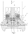
- the tool 6 used for this goes out in particular Figure 2 and 3 emerge.
- the lower tool 8 is a Formed die provided with two rows of holes 11, 12 is.
- the rows of holes are in corresponding rows 14, 15 ( Figure 4) arranged punch 16, 17 assigned to the belong to the upper tool 7.
- the punch 16, 17 are arranged in a punch holder plate 18 which has corresponding openings 19, 20.
- everyone Punches 16, 17 protrude through the opening assigned to it 19, 20 and is thereby axially movable.
- the punch 16, 17 sit with very little play in the corresponding cylindrical opening 19, 20.
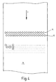
- FIG. 4 shows the punch 16, 17 of the two rows 14, 15 offset laterally against each other so that they refer to the transport direction T of the workpiece 9 overlap each other, or that they are on gap.
- the punch guide plate 18 is with one part of the upper tool 7 connected to the workpiece 9 or the die 8 or a press table holding this 19 touches down before the punch 16, 17 the Touch workpiece 9.
- the die guide plate 18th protruding punch 16, 17 are with their respective inner end preferably tensile and pressure resistant in one Stamp holding plate 21 held. This points to each punch 16, 17 on a stepped bore 22, 23, in each of which a plunger 24, 25 in the longitudinal direction of the Punch 16, 17 slidably held.
- the Punches 16, 17 lie with their top on the plane surface on the underside of the respective tappet 24, 25 on.
- the punch stamp 16, 17 are thus axial in the punch holder plate 21 between an active position in which they are on the lower tool 8 are advanced and a passive position adjustable in the lower tool 8 are moved away.
- the coil springs 28, 29 tension the Punches 16, 17 in front of their passive position.
- the bars 33, 34 are transverse to the working direction of the upper tool 7 slidably in a corresponding Leadership stored. You are there by a spring 37, 38th biased towards their locking position.
- Drive devices 39, 40 are provided, for example a solenoid 41, 42, an armature 43, 44 and a provided between the armature 43, 44 and the bolt 33, 34 Power transmission means 45, 46 are formed.
- the Magnetic coils 41, 42 can be controlled separately, see above that each punch 16, 17 has a bolt 33, 34 and assigned its own drive device 39, 40 is. It is also possible to lock 33, 34 on their Preload release position and they counter the preload by means of a drive device in the locking position to convict. If necessary, a preload can also be dispensed with if the one assigned to the bolt 33, 34 Drive device is designed to him in to move both directions.
- a relief device is common to all punches 16, 17 51 assigned to which as essential Element serves a stamp holding-down plate 52.
- the Drive devices 39, 40 are with a control device 47, 48 connected by a bus system and if necessary, appropriate drivers and decoders are formed.
- the Control device 47, 48 is designed such that each solenoid 41, 42 controlled individually can be. In addition, they are put together as desired Groups of solenoids can be controlled simultaneously.
- the hold-down plate 52 is by one or more Tie rods 53, 54 compliant with the punch guide plate 18 connected.
- the tie rods 53, 54 are located at the ends firmly in the hold-down plate 52 and extend parallel to the punch 16, 17 in corresponding Blind holes 55, 56 of the punch guide plate 18. In these blind holes 55, 56 sit on the bottom thereof supporting coil springs 57, 58 which hold the hold-down plate 52 on the tie rods 53, 54 on the punch guide plate 18 pull.
- the hold-down plate 52 also has bores 61, 62 through which Extensions of the plunger 24, 25 towards the latch 33, 34 extend. The extensions are each of a ring shoulder surrounded on which the hold-down plate 52nd is present.
- the hold-down plate 52 is in its lower one Position where it rests on the tappet holder plate 21, it pushes the plunger 24, 25 so far into the blind holes 22, 23 against the action of the coil springs 28, 29 a that the punch 16, 17 in the active position are and that the extensions of the plunger 24, 25 are the ways release for bolts 33, 34. These can therefore be against very low mechanical resistance from the coil springs 37, 38 or the magnetic coils 41, 42 are moved.
- the perforating press 1 described so far works as follows:
- the upper tool 7 is Perforating press 1 in its top dead center position.
- Upper tool 7 associated sheet metal holder 7a are disengaged with the workpiece 9.
- the stamp holding plate 21 carries. This results in a relative large distance between the punch holder plate 21 and the punch guide plate 18.
- the hold-down plate 52 is therefore all the way down pressed in contact with the punch holder plate 21.
- the hold-down plate 52 holds against the force of the Coil springs 28, 29 the plungers 24, 25 in the active position, i.e. in a position in which the punch 16, 17 protrude out of the punch guide plate 18 at most.
- the distance between the free end faces of the Tappets 24, 25 and the opposite contact surfaces 35, 36 is therefore maximum, so that the bolts 33, 34 easily into the space formed here and can be led out of this, in Figure 7, in which illustrates the movement diagram of the upper tool 7 this can be anywhere in the area A done.
- the control devices 47, 48 control the Magnetic coils 41, 42 in this range of movement of the plunger the perforating press 1 so that the punch 16, 17 the holes in the next down stroke of the ram should generate, locked in their advanced direction become.
- the latch 34 is in the locking position transferred by de-energizing the solenoid 42 becomes.
- the magnetic coil 41 is excited and holds the bolt 33 in release position.
- a new hole pattern can thus be defined in each stroke and punched out. This is shown schematically in FIG. 4 indicated. All conceivable hole positions are illustrated by dots for a portion of the workpiece 9. Holes are only punched out if the punch 17 in question is also locked. By Switching the relevant latch 33, 34 in successive Press strokes can in the given Any hole pattern can be obtained. The press can run continuously with a high number of strokes.
- the relief device 51 with that on the workpiece 9 or another abutment part 7a of the Tool 7 connected.
- the hold-down plate 52 with a separate Drive device to connect the hold-down plate 52 temporarily to the punch holding plate 21 presses or pretensions towards them.
- This drive device can be an electrical or fluid-operated drive device be. It then acts in the axial direction, i.e. in the direction corresponding to arrow 3.
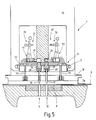
- FIG. 5 A further modified embodiment of the The perforating press 1 or the upper tool 7 is shown in FIG. 5 illustrated.
- the main difference to that The embodiment described above is in the drive of the bolt 33, 34.
- This is by a Fluid cylinder 71, 72 formed in which a piston 73, 74th is slidably mounted and sealed.
- the piston 73, 74 can be both single and double acting in one corresponding cylinder may be arranged.
- Figure 5 is illustrates a double-acting version.
- the piston position is controlled via the corresponding one Changeover directional control valves 75, 76, which can be electrically controlled, for example are.
- Changeover directional control valves 75, 76 which can be electrically controlled, for example are.
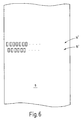
- the tappet guide plate 18, the tappet holder plate 21, the locking device 31, 32 and the relief device 51 can be designed as an exchangeable cassette be, for example, from the side into the tool 7 can be inserted. So one can in the simplest way Adaptation to different hole spacing or hole shapes be achieved. E.g. can instead of punches 16, 17 with a round cross section also three, four or polygonal punches are used, as in FIG. 6 is illustrated using two rows of tappets 14 ', 15', which are only shown here in part. In addition, the sheet metal transport on an air cushion to avoid damage.
- a press in particular a perforating press 1 provided with a tool 7 on which several punches 16, 17 are adjustable.
- To lock the Punches 16, 17 in the active position serve as locking devices 31, 32 to change the selection by a relief device 51 will be released if the punch 16, 17 out of engagement with the workpiece 9th and are within a certain safety margin this.
- the relief device enables a low-performance, yet quick adjustment of the Locking devices 31, 32 and thus a change the punch selection with every press stroke also at high-speed presses.
- Preloading the punch 16, 17 on their passive position allows the Avoidance of contact between passive punches 16 and the workpiece 9 during the press stroke. This avoids workpiece damage.
Landscapes
- Engineering & Computer Science (AREA)
- Mechanical Engineering (AREA)
- Life Sciences & Earth Sciences (AREA)
- Forests & Forestry (AREA)
- Perforating, Stamping-Out Or Severing By Means Other Than Cutting (AREA)
- Presses And Accessory Devices Thereof (AREA)
- Press Drives And Press Lines (AREA)
Applications Claiming Priority (2)
| Application Number | Priority Date | Filing Date | Title |
|---|---|---|---|
| DE19825843 | 1998-06-10 | ||
| DE19825843A DE19825843C2 (de) | 1998-06-10 | 1998-06-10 | Perforierpresse mit Einzelstempelsteuerung |
Publications (2)
| Publication Number | Publication Date |
|---|---|
| EP0963802A2 true EP0963802A2 (fr) | 1999-12-15 |
| EP0963802A3 EP0963802A3 (fr) | 2001-04-18 |
Family
ID=7870464
Family Applications (1)
| Application Number | Title | Priority Date | Filing Date |
|---|---|---|---|
| EP99110929A Withdrawn EP0963802A3 (fr) | 1998-06-10 | 1999-06-04 | Presse à perforer avec système d'entrainement d'un poinçon unique |
Country Status (3)
| Country | Link |
|---|---|
| EP (1) | EP0963802A3 (fr) |
| CZ (1) | CZ202999A3 (fr) |
| DE (1) | DE19825843C2 (fr) |
Cited By (4)
| Publication number | Priority date | Publication date | Assignee | Title |
|---|---|---|---|---|
| WO2009101224A1 (fr) | 2008-02-15 | 2009-08-20 | Eisen Xxi, S.L. | Machine automatique pour poinçonnage et découpe de feuillards |
| ITVE20130049A1 (it) * | 2013-09-20 | 2015-03-21 | Dallan Spa | Testata di punzonatura per macchine punzonatrici.- |
| CN104626373A (zh) * | 2014-12-22 | 2015-05-20 | 中国电子科技集团公司第二研究所 | 低温共烧陶瓷高速冲孔单元 |
| IT202200017547A1 (it) * | 2022-08-24 | 2024-02-24 | Corrada Spa | Dispositivo per stampi di tranciatura per lamierini ad uso elettrico |
Families Citing this family (4)
| Publication number | Priority date | Publication date | Assignee | Title |
|---|---|---|---|---|
| DE10309952A1 (de) * | 2003-03-07 | 2004-09-16 | Heidelberger Druckmaschinen Ag | Verfahren zur Unterstützung des Einrichtens einer Stanzvorrichtung mit veränderbarem Lochmuster |
| DE102004063952B4 (de) * | 2004-04-10 | 2007-10-04 | Hölzel Stanz- und Feinwerktechnik GmbH & Co. KG | Presseneinheit zum Pressen und/oder Stanzen und/oder Biegen von Werkstücken |
| DE102004017677B4 (de) * | 2004-04-10 | 2006-03-16 | Hölzel Stanz- und Feinwerktechnik GmbH & Co. KG | Werkzeugeinheit zum Pressen und/oder Stanzen und/oder Biegen von Werkstücken |
| DE102016114026B4 (de) * | 2016-07-29 | 2023-09-21 | Tox Pressotechnik Gmbh & Co. Kg | Vorrichtung zum Prägen einer Vertiefung in ein plattenartiges Werkstück und Durchstanzen der geprägten Vertiefung |
Family Cites Families (4)
| Publication number | Priority date | Publication date | Assignee | Title |
|---|---|---|---|---|
| US4480782A (en) * | 1982-12-30 | 1984-11-06 | Toyota Jidosha Kabushiki Kaisha | Punch press die assembly with punch selecting mechanism |
| JPH02124295A (ja) * | 1988-10-28 | 1990-05-11 | Ushio Kk | 多軸穿孔装置 |
| JPH0813387B2 (ja) * | 1990-11-08 | 1996-02-14 | 株式会社三協マニテック | パンチング板打抜き加工装置 |
| DE19622843A1 (de) * | 1996-06-07 | 1997-12-11 | Schuler Pressen Gmbh & Co | Vorrichtung zum Perforieren von Blechen |
-
1998
- 1998-06-10 DE DE19825843A patent/DE19825843C2/de not_active Expired - Fee Related
-
1999
- 1999-06-04 EP EP99110929A patent/EP0963802A3/fr not_active Withdrawn
- 1999-06-07 CZ CZ992029A patent/CZ202999A3/cs unknown
Cited By (9)
| Publication number | Priority date | Publication date | Assignee | Title |
|---|---|---|---|---|
| WO2009101224A1 (fr) | 2008-02-15 | 2009-08-20 | Eisen Xxi, S.L. | Machine automatique pour poinçonnage et découpe de feuillards |
| ES2330402A1 (es) * | 2008-02-15 | 2009-12-09 | Eisen Xxi, S.L. | Maquina automatica para punzonado y corte de llantas. |
| ES2330402B1 (es) * | 2008-02-15 | 2010-09-13 | Eisen Xxi, S.L. | Maquina automatica para punzonado y corte de llantas. |
| US8522659B2 (en) | 2008-02-15 | 2013-09-03 | Eisen Xxi, S.L. | Automatic machine for punching and cutting wheel rims |
| ITVE20130049A1 (it) * | 2013-09-20 | 2015-03-21 | Dallan Spa | Testata di punzonatura per macchine punzonatrici.- |
| EP2853318A1 (fr) * | 2013-09-20 | 2015-04-01 | Dallan S.P.A. | Tête de poinçon pour machines de poinçonnage |
| CN104626373A (zh) * | 2014-12-22 | 2015-05-20 | 中国电子科技集团公司第二研究所 | 低温共烧陶瓷高速冲孔单元 |
| IT202200017547A1 (it) * | 2022-08-24 | 2024-02-24 | Corrada Spa | Dispositivo per stampi di tranciatura per lamierini ad uso elettrico |
| WO2024042401A1 (fr) * | 2022-08-24 | 2024-02-29 | Corrada S.P.A. | Dispositif pour matrices de cisaillement pour tôles à usage électrique |
Also Published As
| Publication number | Publication date |
|---|---|
| EP0963802A3 (fr) | 2001-04-18 |
| CZ202999A3 (cs) | 1999-12-15 |
| DE19825843A1 (de) | 1999-12-16 |
| DE19825843C2 (de) | 2003-03-20 |
Similar Documents
| Publication | Publication Date | Title |
|---|---|---|
| DE3875283T2 (de) | Verfahren und einrichtung zur herstellung von insbesondere metallischen etiketten mit einer doppelten codifikation, davon einen code mit ausgeschnittenen balken, und derartig hergestellte etiketten. | |
| EP0326639B1 (fr) | Commande de soupape pour outil d'enfoncement pneumatique | |
| EP0278046A1 (fr) | Outil pour l'estampage de figures de matrice complexes à partir d'un ruban métallique | |
| EP3917735A2 (fr) | Machine à estamper/perforer | |
| DE19641411A1 (de) | Hydraulische Tiefzieheinrichtung | |
| DE3339503C2 (de) | Stanzmaschine und Werkzeugsatz für Stanzmaschinen | |
| DE19825843C2 (de) | Perforierpresse mit Einzelstempelsteuerung | |
| DE3042158C2 (de) | Einrichtung zum Herstellen von Durchzügen an Werkstücken auf einer Schneidpresse | |
| DE3905789C2 (de) | Stempelpresse | |
| DE1602584A1 (de) | Winkelwerkzeugsatz | |
| EP3946853B1 (fr) | Machine pour la perforation et l'emboutissage avec un cadre four la fixation du materiel a travailler | |
| DE3423543A1 (de) | Presse und verfahren zur herstellung derselben | |
| DE202005010990U1 (de) | Vorrichtung zum Stanzen und/oder Umformen von Werkstücken | |
| DE3780143T2 (de) | Auswerfer einer stanzpresse fuer metallplatten. | |
| DE3440809A1 (de) | Verfahren und vorrichtung zum verbinden von aufeinanderliegenden blechen durch stanznocken | |
| DE19727344C2 (de) | Linearstellglied | |
| EP0963801B1 (fr) | Presse pour fabriquer des pièces de travail variables | |
| DE602004001117T2 (de) | Doppelwirkendes Nocken-Presswerkzeug | |
| DE2704246A1 (de) | Pressenkopf mit mehreren stempeln zum wahlweisen abstreifen | |
| DE69210210T2 (de) | Revolverstanzmaschine | |
| DE3136753C2 (de) | Tiefzieheinrichtung für Platine | |
| EP4070943A1 (fr) | Dispositif de presse permettant de presser des pièces en bois, en matière plastique, en métal et similaires | |
| EP3946854A1 (fr) | Machine de poinçonnage/perforation | |
| DE3876152T2 (de) | Blechtiefziehvorrichtung. | |
| DE8905741U1 (de) | Bearbeitungsvorrichtung zum Einsetzen in eine Presse |
Legal Events
| Date | Code | Title | Description |
|---|---|---|---|
| PUAI | Public reference made under article 153(3) epc to a published international application that has entered the european phase |
Free format text: ORIGINAL CODE: 0009012 |
|
| AK | Designated contracting states |
Kind code of ref document: A2 Designated state(s): AT BE CH DE ES FR GB IT LI SE |
|
| AX | Request for extension of the european patent |
Free format text: AL;LT;LV;MK;RO;SI |
|
| PUAL | Search report despatched |
Free format text: ORIGINAL CODE: 0009013 |
|
| AK | Designated contracting states |
Kind code of ref document: A3 Designated state(s): AT BE CH CY DE DK ES FI FR GB GR IE IT LI LU MC NL PT SE |
|
| AX | Request for extension of the european patent |
Free format text: AL;LT;LV;MK;RO;SI |
|
| 17P | Request for examination filed |
Effective date: 20010516 |
|
| AKX | Designation fees paid |
Free format text: AT BE CH DE ES FR GB IT LI SE |
|
| 17Q | First examination report despatched |
Effective date: 20021009 |
|
| GRAH | Despatch of communication of intention to grant a patent |
Free format text: ORIGINAL CODE: EPIDOS IGRA |
|
| STAA | Information on the status of an ep patent application or granted ep patent |
Free format text: STATUS: THE APPLICATION IS DEEMED TO BE WITHDRAWN |
|
| 18D | Application deemed to be withdrawn |
Effective date: 20031202 |